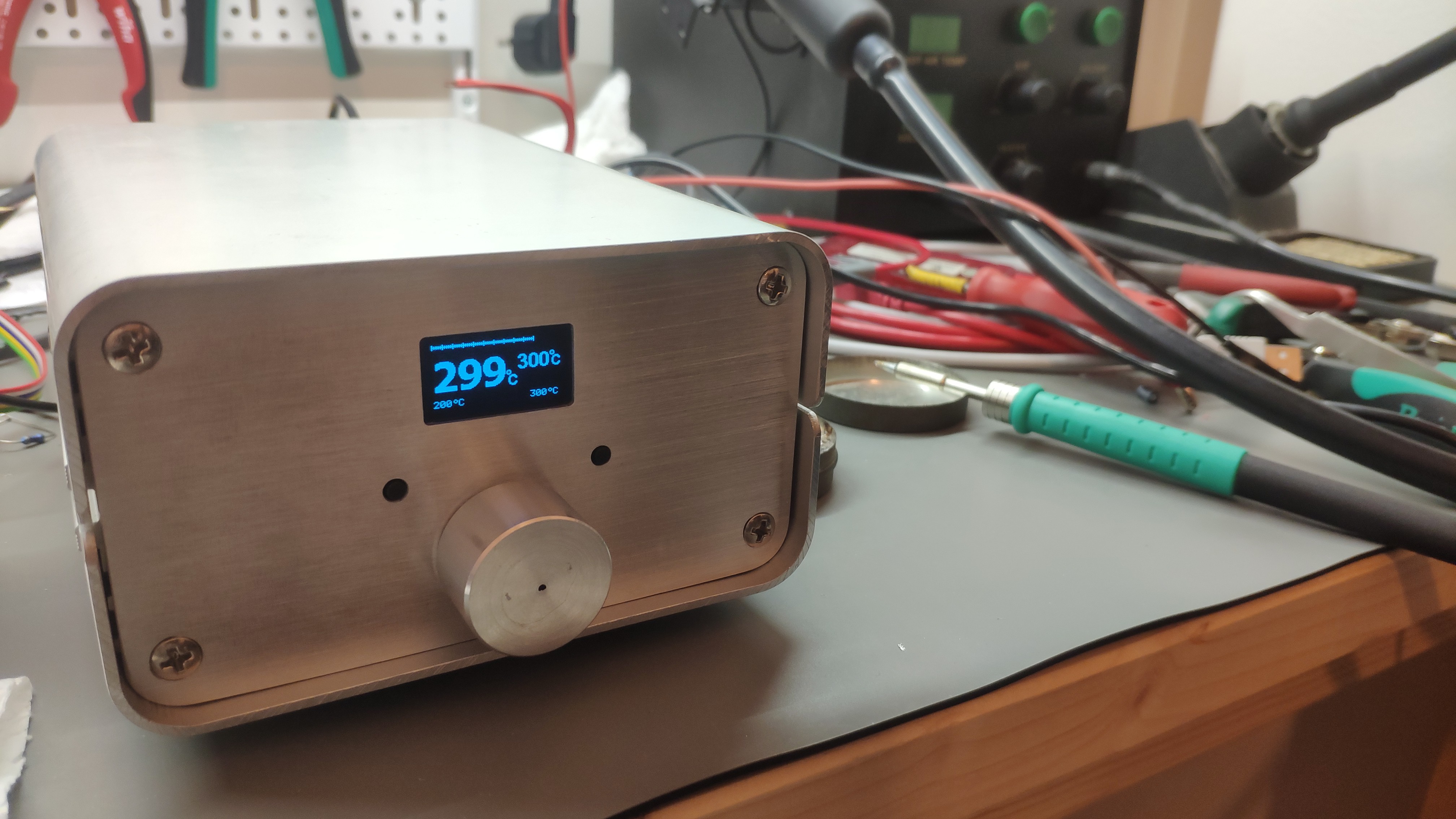
After a long time... everything is ready for usage.
There were two big problems, which were discovered during final assembling. I have removed the programmer and tried to power the circuit itself via DC/DC converter.
I have to made a new boards with fixed DC/DC connection and zero-cross detection. New capacitors, different GND connection and new zero-cross circuit. How did I discover it?
Just disconnected programmer, it means, that there was no a general GND anymore. Everything was isolated. There was a lot of noise on 3v3 from LDO, which transferred into input (5V). Which made circuit really unstable. So some capacity and better GND re-planning was required.
Next problem (I think, the main) was on the soldering tip detection. After a global GND missing, one input on OPAMP was flying. It means -> noise on the output. So I have to identified and fixed it. Hopefully it was only on the SW side.
So here are the final results.

So what is missing here?
Nothing... maybe a stand :).
 Andy
Andy
Discussions
Become a Hackaday.io Member
Create an account to leave a comment. Already have an account? Log In.
Thank you,
I didn't want to add some socket on the switches. Maybe I can do that, but I like it is :).
Are you sure? yes | no
Yeah, quite possible it is way better to use than it looks on video.
Are you sure? yes | no
The soldering station turned out really great! It looks better than our 400 Euro JBC.
May be you can put some "hats" on the micro switches to make them more convenient to use. Basically just a disc as a button with a little tube on the backside that is put over the micro switch.
Are you sure? yes | no