Andy
Andy-
Device released
02/27/2020 at 07:09 • 4 commentsI was waiting for some last parts to make the device "ready for usage".
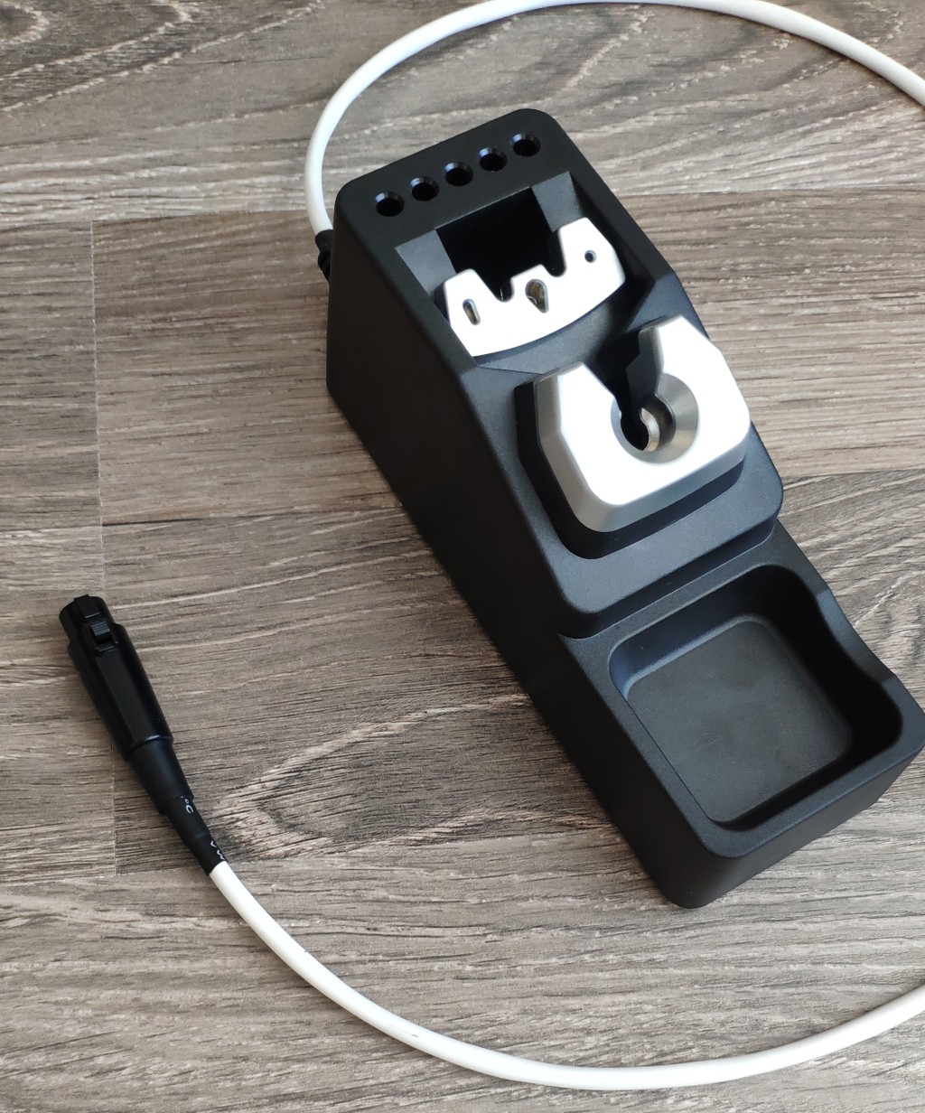
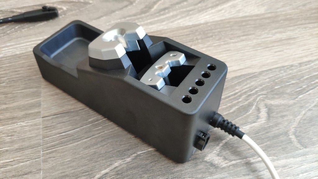
Of course, it was also usable without this last missing part (a stand). But why not make this station little bit better? So I have ordered some "Chinese" soldering station holder, which was pretty close to original JBC holder. Here are some results, after necessary modifications...
![]()
![]()
So I think, now I can set the project to "finished".
The last most important think is that ... . After very long thinking I have made a decision, that I will make the project a public. Anyone can make this device by yourself. I will be very happy, if I see some other users same satisfied as me.
Happy building!
-
Release ready
12/26/2019 at 19:36 • 3 commentsAfter a long time... everything is ready for usage.
There were two big problems, which were discovered during final assembling. I have removed the programmer and tried to power the circuit itself via DC/DC converter.
I have to made a new boards with fixed DC/DC connection and zero-cross detection. New capacitors, different GND connection and new zero-cross circuit. How did I discover it?
Just disconnected programmer, it means, that there was no a general GND anymore. Everything was isolated. There was a lot of noise on 3v3 from LDO, which transferred into input (5V). Which made circuit really unstable. So some capacity and better GND re-planning was required.
Next problem (I think, the main) was on the soldering tip detection. After a global GND missing, one input on OPAMP was flying. It means -> noise on the output. So I have to identified and fixed it. Hopefully it was only on the SW side.
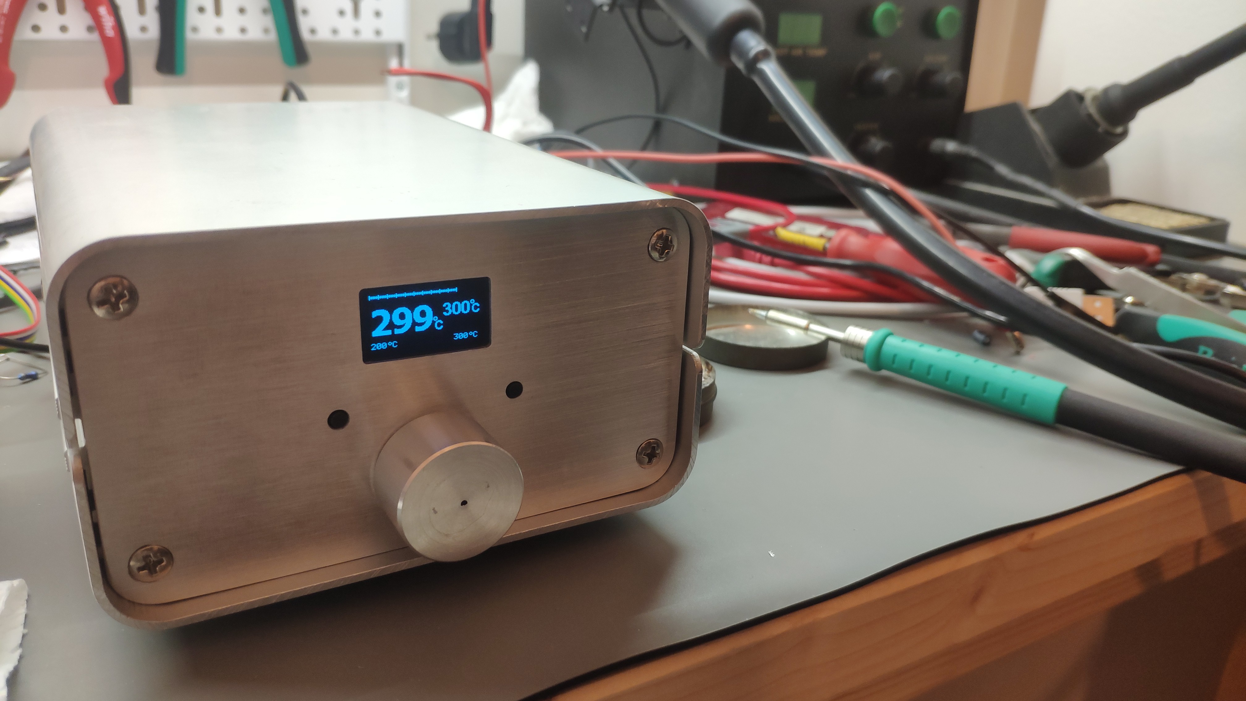
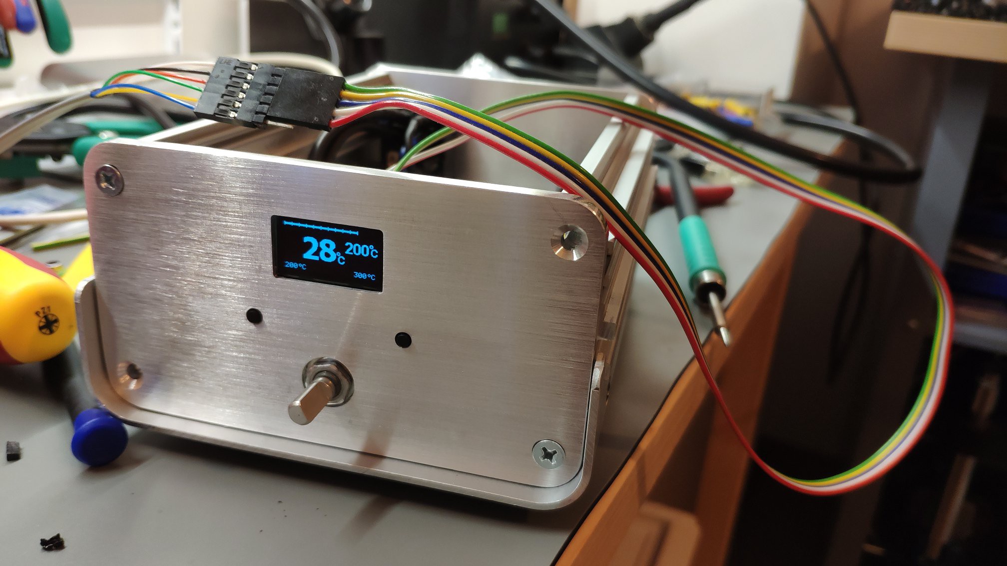
So here are the final results.
![]()
So what is missing here?
Nothing... maybe a stand :).
-
Device assembled
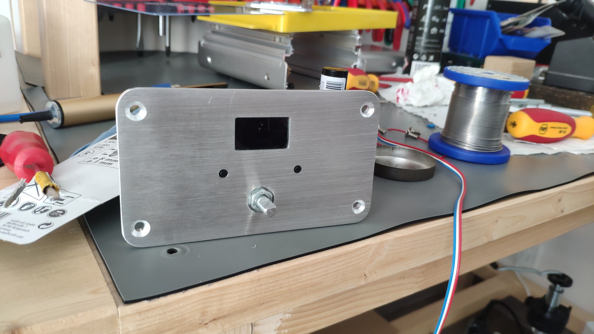
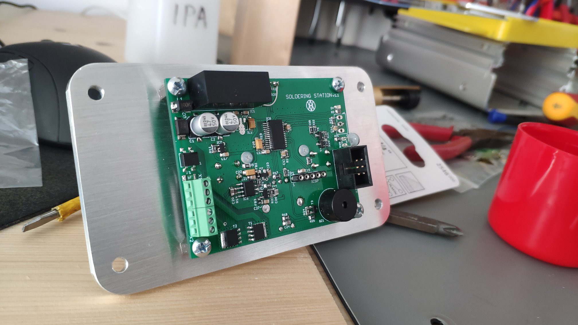
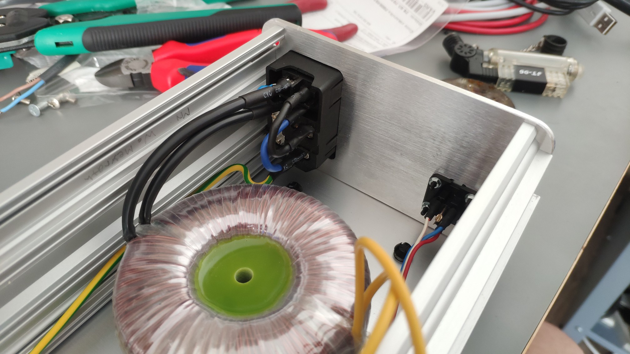
10/26/2019 at 18:16 • 0 commentsI was waiting for housing to be fabricated a little bit. This is the main reason, why I didn't post any progress here.
Meanwhile I was working on different project (CNC). But this is an another story :).I think better is to post pictures without useless slacking...
![]()
![]()
![]()
![]()
Hopefully nothing has been broken during final assembling.Now I have to wait for encoder knob fabrication. I think, this is the last part of the puzzle, which is missing now. Of course stand is also missing, but this is not major thing, which could breaks soldering station using.
-
SW ready for using
09/20/2019 at 09:37 • 0 commentsI would like sum-up what is currently working and what is the future prune.
All pending features, which were blocking a real using have been fixed, hopefully. Some of them have been moved into future, because they are only minor improvements, I think.
Ok, lets go to sum-up (I will re-use TODO list from previous log):
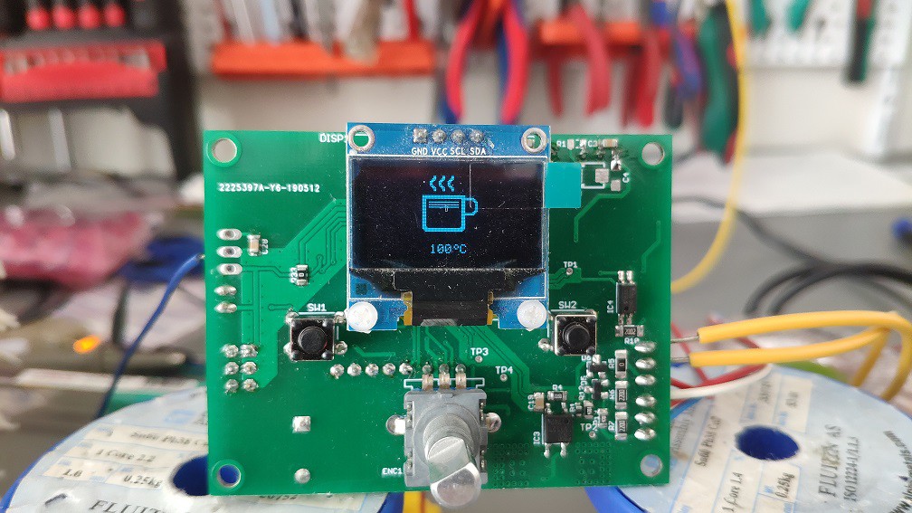
-sleep mode
- A sleep temperature is also showed. This is starting after sleeping timeout has been elapsed only when pen is inside a stand. It can be disabled of course.
![]()
-
protection handling
- Added Watchdog and some min/max checking
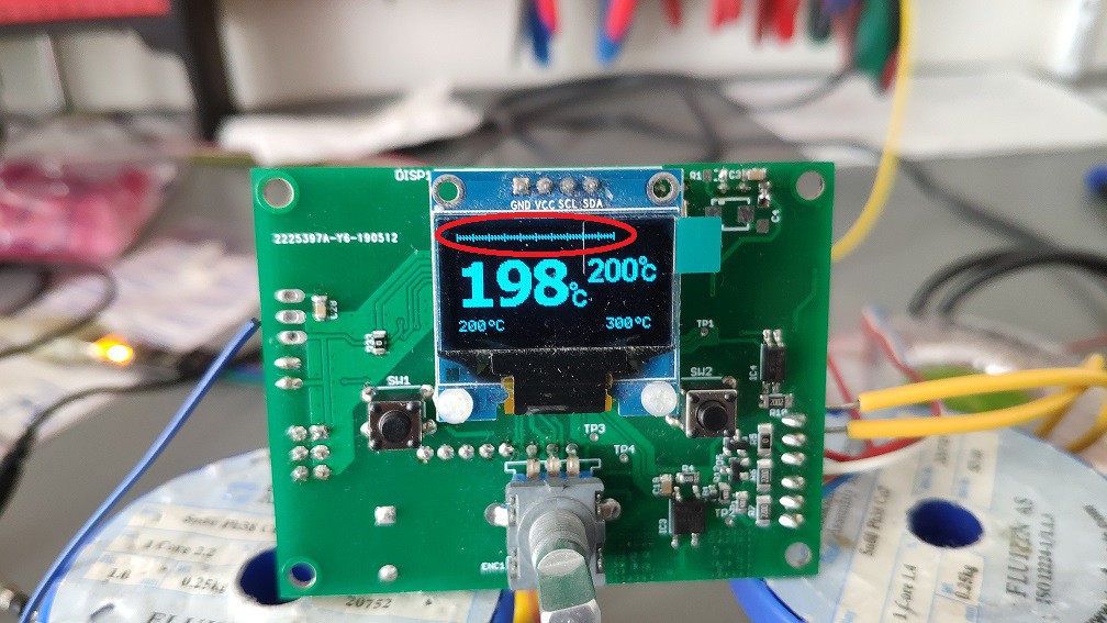
-power bar handling
- If a temperature difference is bigger than zero, power-bar is filled. It also indicates pen heating.
![]()
-
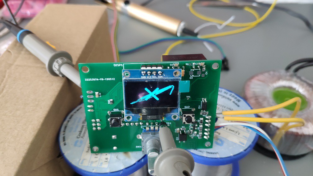
pen detection
- If then pen is missing, logo with crossed pen will be shown. It also turn-off heating. After pen is connected back, it automatically starts heating.
![]()
- °C/F switching
- I don't want to waste a time with this selection. I don't want to use F for temperature displaying. Maybe I can add it in the feature for some user request.
-brightness regulation
- There are 10 options to set brightness level. Levels are directly represented, so user shouldn't save the parameters to see, how the brightness really looks like.
Others not previously mentioned improvements:
- multiplier
- Temperature could be de/increase not only be 1 degree. It could be changed by 2, 3, ... 10. User doesn't need to go step-by-step if he wants to de/increase temperature eg. 200->300.
- beep
- All user inputs could have also sound echo.
- performance improvements
- Heating now takes less time. Here I need to experiment a little bit to get more power. But I it's not urgent, so I am shifting it to the future.
That's it. I would like to say really thanks all people, who helped and gave me some advice for SW/HW improvements.
I think, that SW part is ready for usage. Now I will move to housing. I have to change my previous drafts a little bit to be matching with actual design. -
First real heating
08/15/2019 at 06:54 • 0 commentsAfter some time, I would like to summarize, what was is actually done and bring some info.
I was struggling with some not working parts like EEPROM, correct temperature measuring, heating... , but finally I have found the root cause and fixed it. Last part, which needs to be clarified, was user interface. I have made some, how to say "preliminary" version, but It looks fine from my side. Maybe I will modified it a little bit afterwards.
What is actually working/done:
- User interface
- buttons handling (rotary encoder, user buttons)
- temperature measuring (ambient, heating)
- display controlling (SSD1306)
- parameters saving (EEPROM)
- calibration (external more precision temperature meter required)
What needs to be fixed/done:
- sleep mode
- protection handling
- power bar handling
- pen detection
- stand detection
- °C/F switching
- brightness regulation
Here are some videos, how the real prototype looks like.
Cold heating from ambient to target temperature (25->200)
User interface, menu handlingActually there is still lot of work. Next step is to verify, if heating algorithm is the correct one, or some tuning is required.
-
PCB ready for assembly
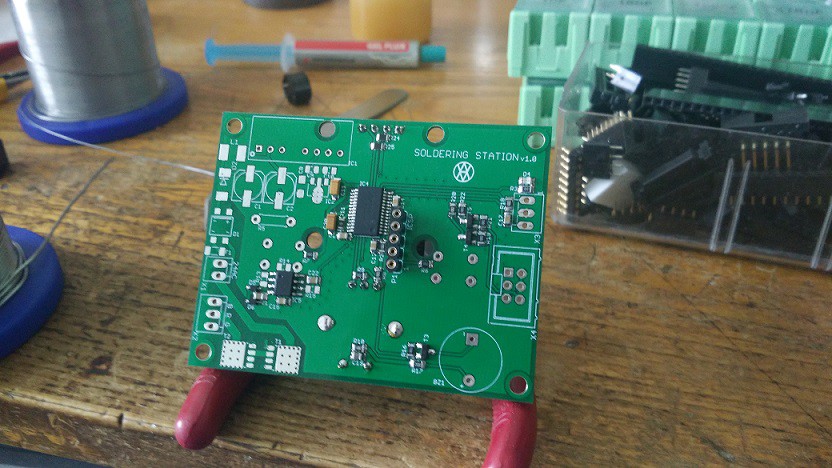
06/04/2019 at 19:42 • 0 comments![]() Magic happened and PCBs are at home, finally... .
Magic happened and PCBs are at home, finally... .![]() On the left side is version 1.0 and on the right side is new PCB version 1.1 .
On the left side is version 1.0 and on the right side is new PCB version 1.1 .![]() Some components has been taken from previous version. Finally "Hello world!" (LEDblinking) is working as well.
Some components has been taken from previous version. Finally "Hello world!" (LEDblinking) is working as well.
Now I have to buy some missing components. After that I will continue in assembling. -
Moving forward
05/13/2019 at 06:56 • 0 commentsFirst, I would like to say sorry for not posting any progress here.
I was moving my home laboratory to new location. More space, more gadgets, new ideas ;).
Previous concept has some issues. Like zero-cross detection was not working like expectations. (I have already published working idea).
Another problem was with temperature measuring. Maybe you know that, temperature is changing in uV. Previous solution has lot of noise on AMP inputs. So I have modified the measuring technique a little bit. Now I am measuring it like a differential. So noise is on the both of inputs and it equals to quite good signal.Last problem was with the switching itself. I was noticed on this problem by @Attila Kovács . He gave me a lot of advice, which I would like to say, thank you.
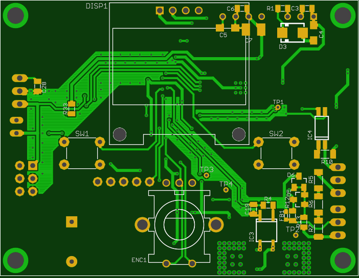
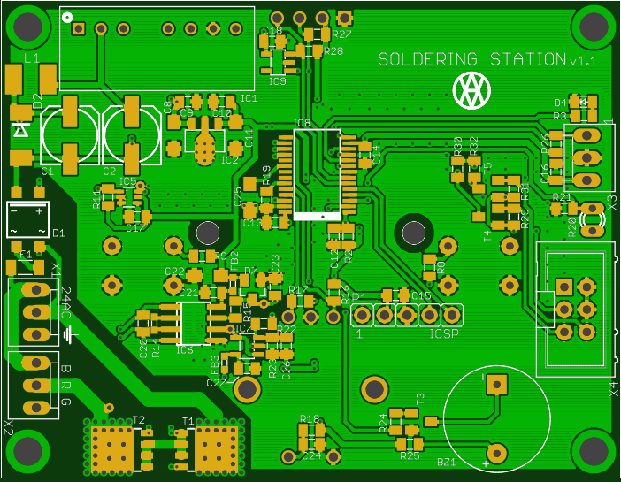
After some modifications I have finished a new PCB design v1.1. (I hope, this is the last one :) ).
![]()
![]()
Now I have to wait for fabrication... .
-
Some progress
10/01/2018 at 18:10 • 2 commentsSorry for the longer delay between posting some progress. I didn't have much time for continuing in this project. Of course there were some tryings and strugglings with zero-cross detection.
First idea was, to use for zero-cross detection basic external interrupt. I used signal generator for testing. Input signal was sinus @50Hz. When I connected the signal to MCU, there were some delay between reaching the zero level and interrupt itself. MCU was running with 8MHz internal oscillator. Delay was ~4ms, what is unacceptable (1/50Hz = 25ms). I have tested it on 8-bit MCU, to be sure, if there is something wrong. But results were the same. "Maybe there is a problem with internal oscillator". So I have decided to use external one, but without success.
So I have switched the input signal to square and it was working well. After some analysis (including datasheet) I have figured out, that is missing "Schmidt circuit" on MCU's inputs. The edge of input sinus signal is not so perpendicular as expectations. It means that, external interrupt mechanism can't reach this edge.
Finally I have the solution, how to fix this problem. I didn't want to use 4-way rectifier and stuff like that. So a comparator is the right way. But, which one to use, external or internal... . External has some advantages, so I decided to use this one.
I have made only simulation, but it should work ;) -
OLED SSD1306 is working...
07/24/2018 at 20:06 • 0 commentsIt was funny to port i2c driver from 8-bit to 32-bit MCU. Lot of changes, but it was a big step forward. So seems to be that, I have successfully ported my previously used OLED SSD1306 driver.
![]()
It just counts from 0-300, but image was stripped ;). I guess, for basic presentation is enough.
There is a lot of TODO points, but next step will be displaying value based on encoder rotation... . -
Prototype assembling
07/22/2018 at 14:23 • 0 commentsI have had some time to assembly a first prototype. There is a minimum components to verify basic functionality.
![]()
Now is time to check if everything is working in quick steps.
![]()
Hello world is seems to be working as well ;)
 Magic happened and PCBs are at home, finally... .
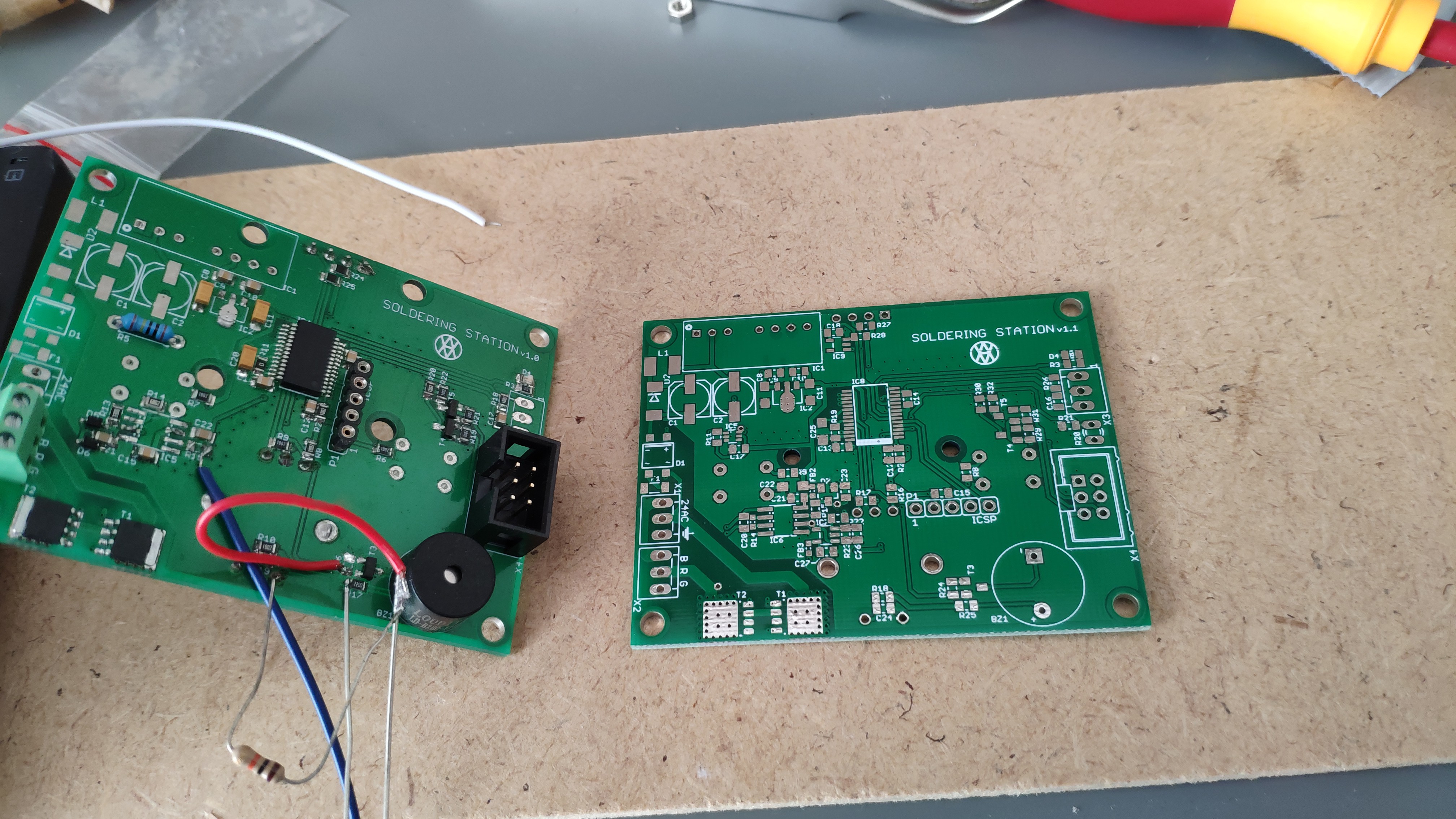 On the left side is version 1.0 and on the right side is new PCB version 1.1 .
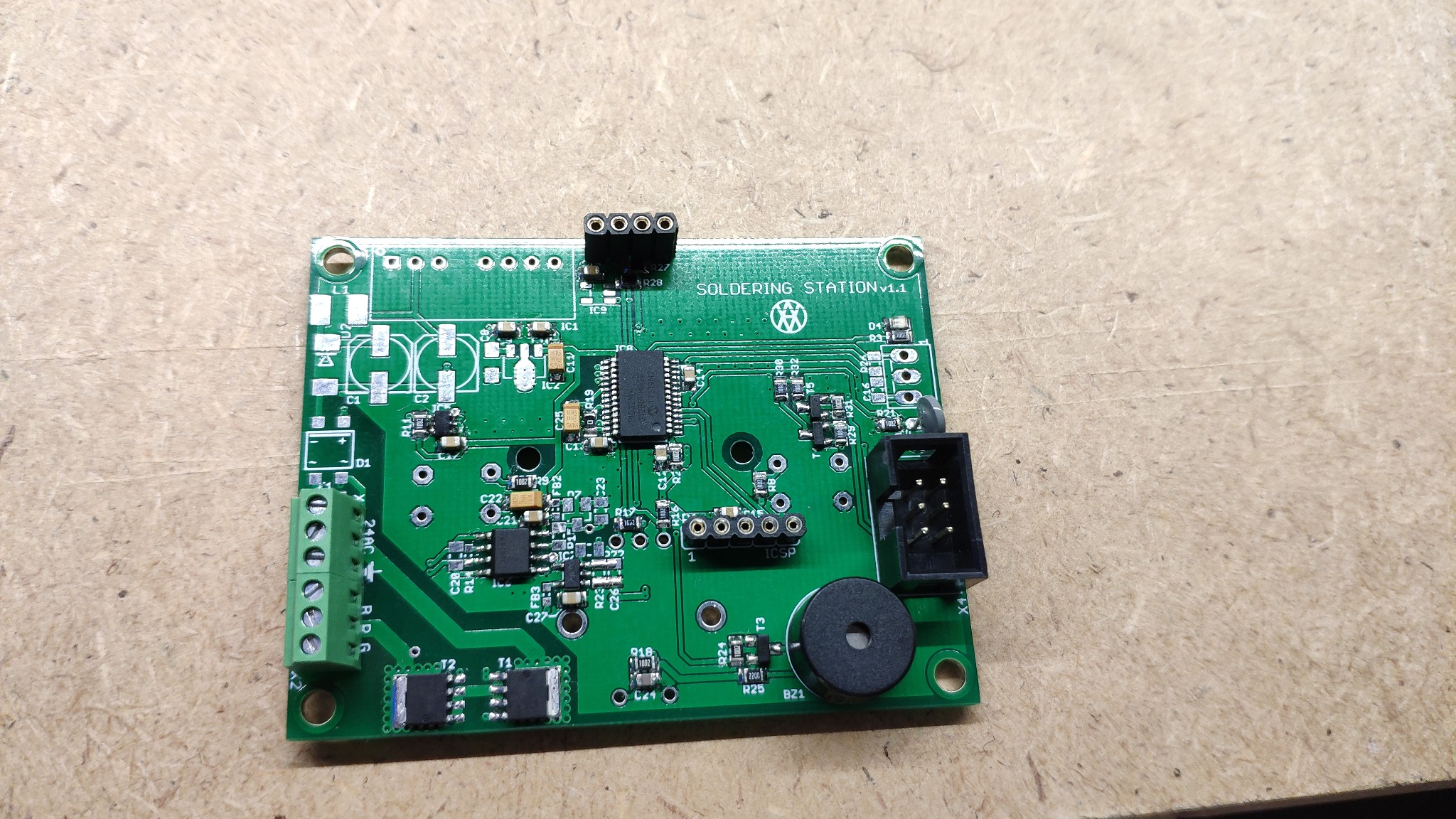 Some components has been taken from previous version. Finally "Hello world!" (LEDblinking) is working as well.