This could be a very tricky part depending on your bike. Components needed:
- Black Heat Shrink Tube 3:1 (1m x 10mm)
- Black Heat Shrink Tube 3:1 (2m x 5mm)
- 1 x Blue Silicon AWG 22 wire (5m)
- 1 x Red Silicon AWG 22 wire (10m)
- 1 x Black Silicon AWG 22 wire (10m)
- Cable ties (200mm, 100pcs)
- Cable ties (100mm, 100pcs)
- Soldering iron + soldering material
- Glue (e.g. super glue)
- Set of screwdrivers
- Heat gun
I am assuming that the headlight, rear light, motor and eBox are ready to be installed in your bike. Hence, the only thing to do is to 'convert' the braking levers so they can act as pushbuttons. I am trying to use a non-invasive methodology in order to implement the pushbutton effect in the braking levers.
First thing I did was to spend a while trying to analyse the best way to attach cables and also if it possible to take advantage of conductive materials. My plan is the following:
- The braking light will be activated when the user pulls the braking lever. However, in my case there was a huge gap to cover. My solution was to use a spring as you can see in the pictures.
- The indicator will be activated when the user pushes the lever forward.
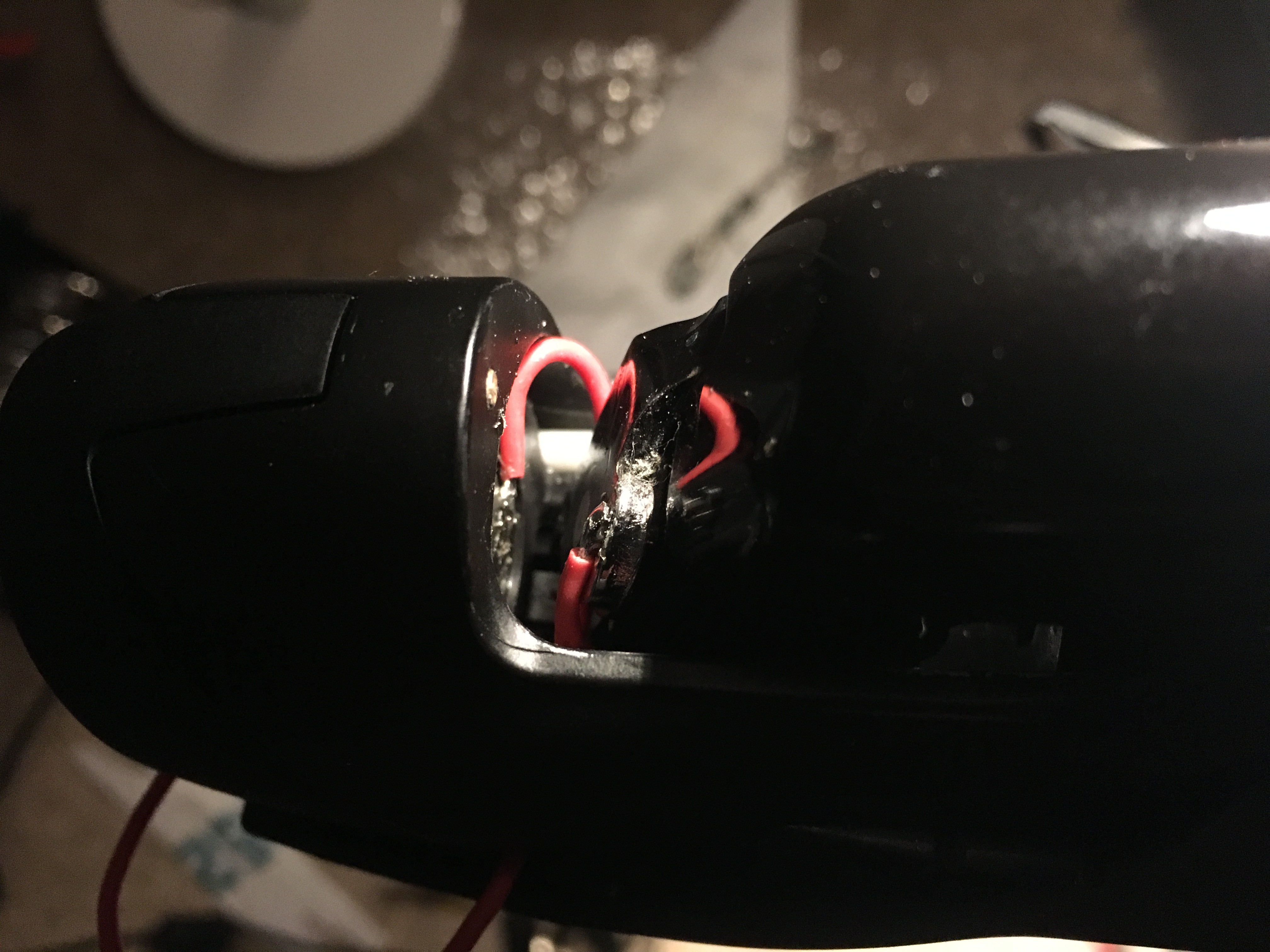
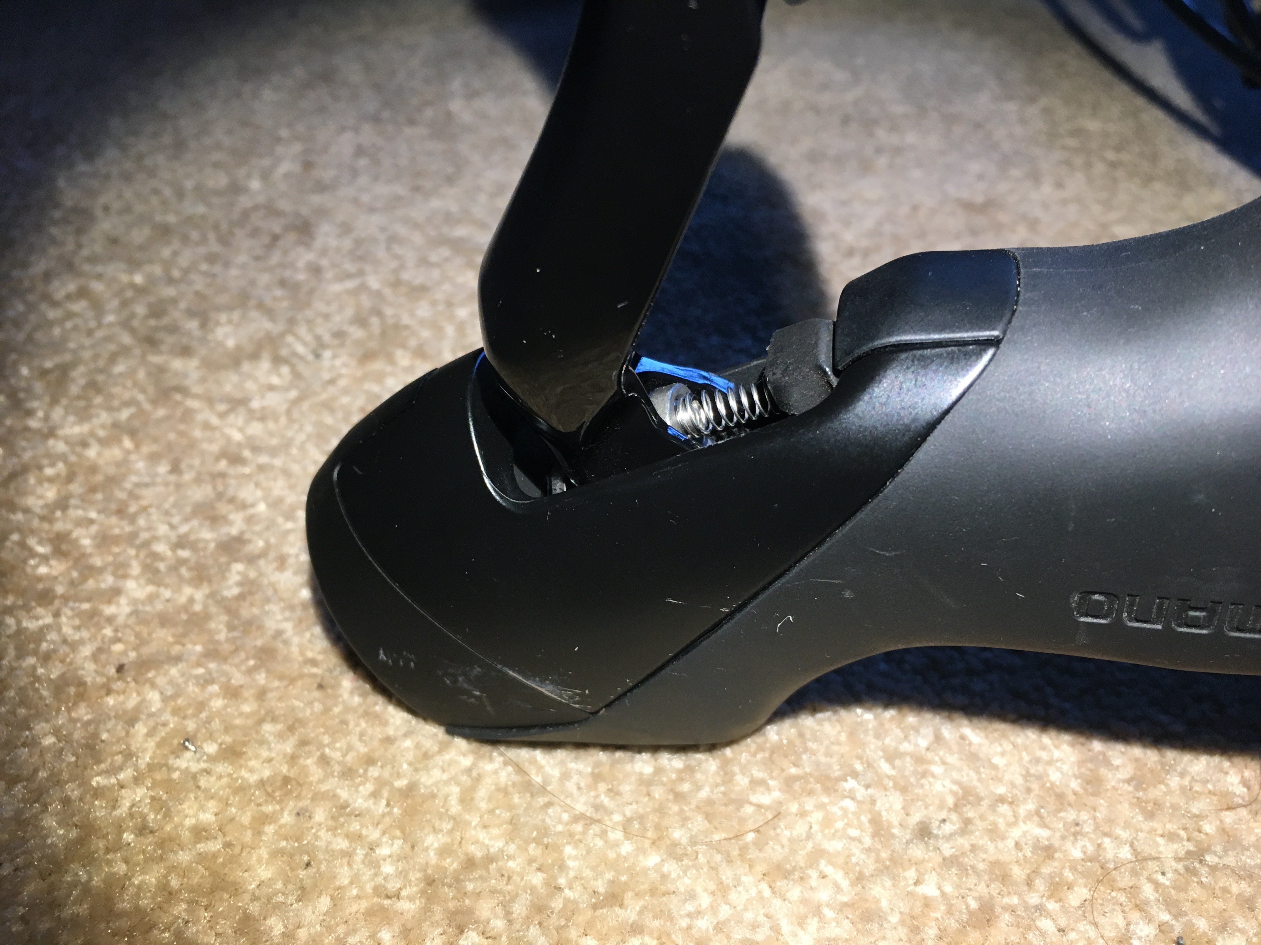
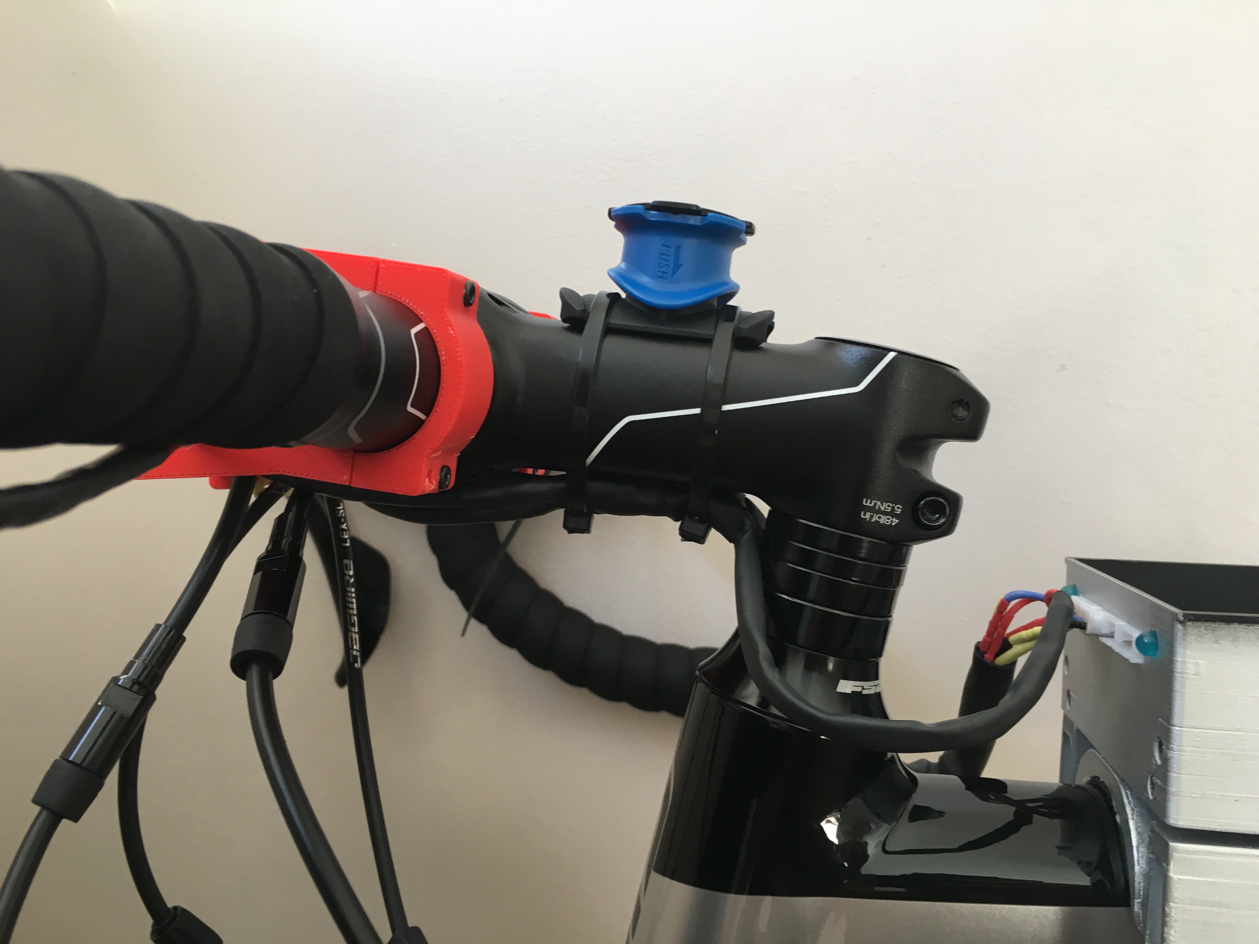
Now it is time for using your skills and decide which is the best way for routing all cables. I think the best way to explain it is to show some pictures (again).


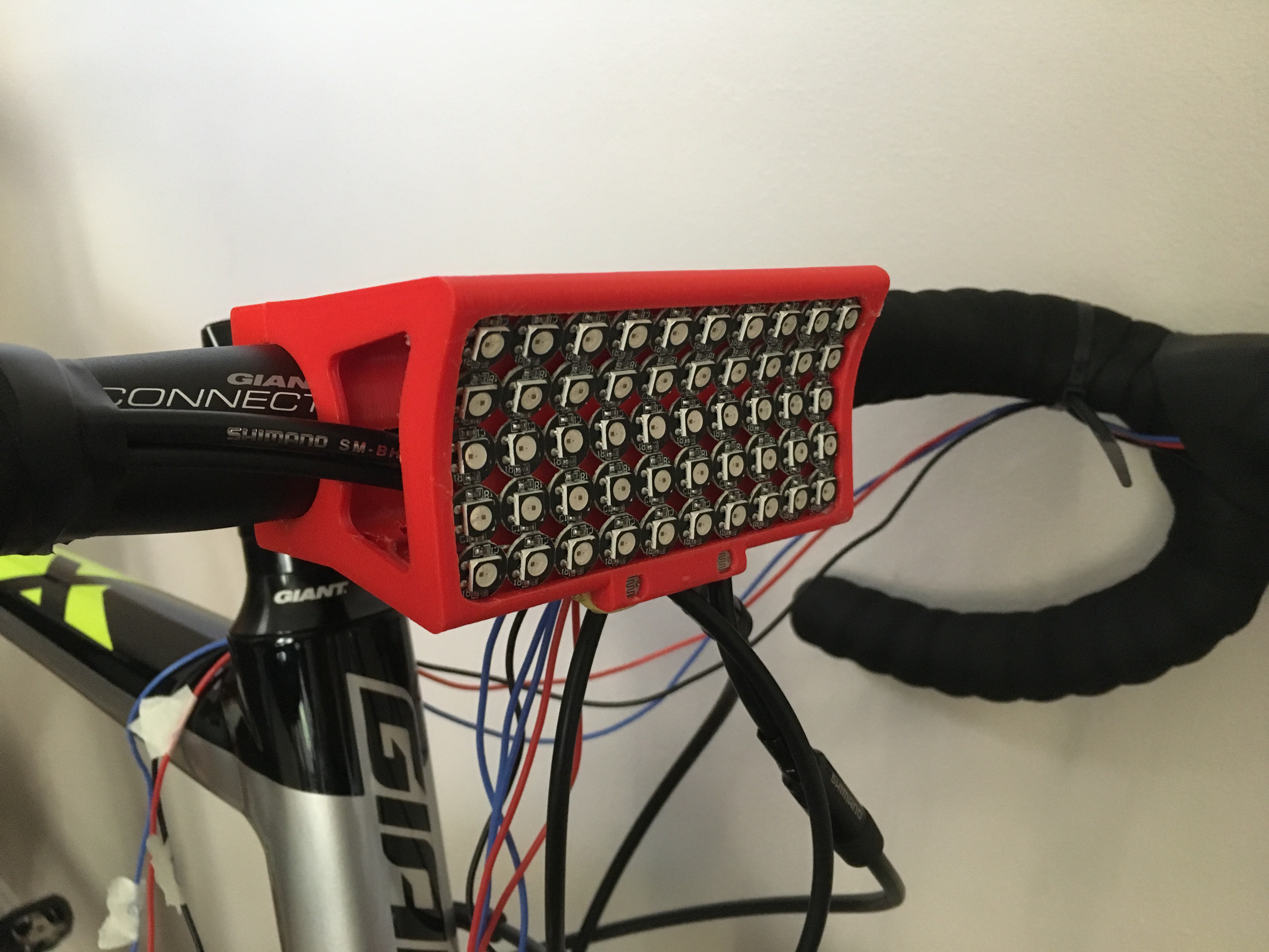
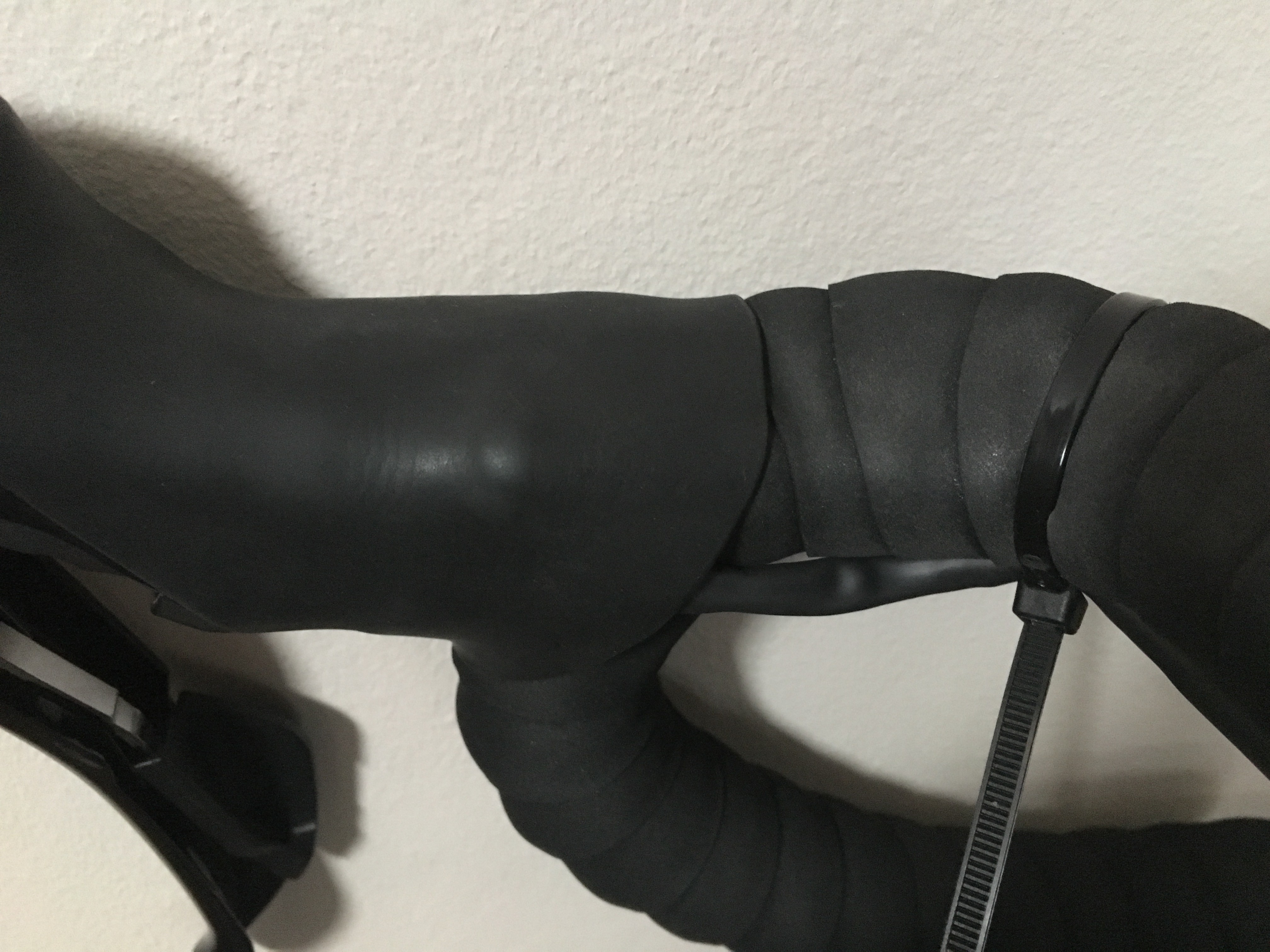
UPDATE 21-10-18
After spending some time (a lot!) testing the hardware/ software stages of this project, I have to acknowledge that the tweaked levers worked amazingly well. Here is the final picture!

Q&A Section
Did you have use any invasive methodology (e.g. drilling) for the wiring?
No! The bike I am using was not precisely cheap, so I was forced to use non-invasive methods for the wiring. The main advantage is that you can remove anytime!
 Javier Betancor
Discussions
Become a Hackaday.io Member
Create an account to leave a comment. Already have an account? Log In.