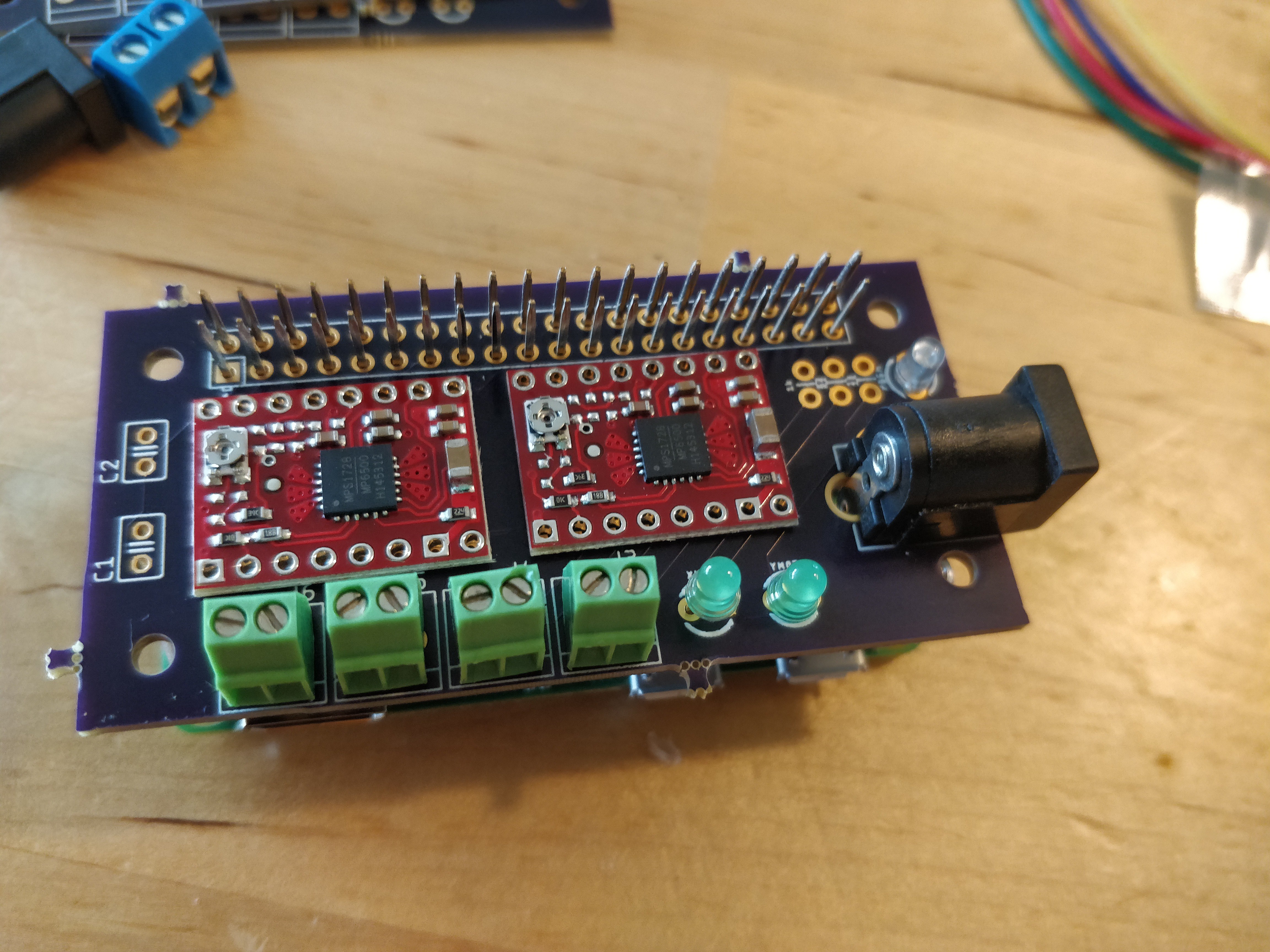
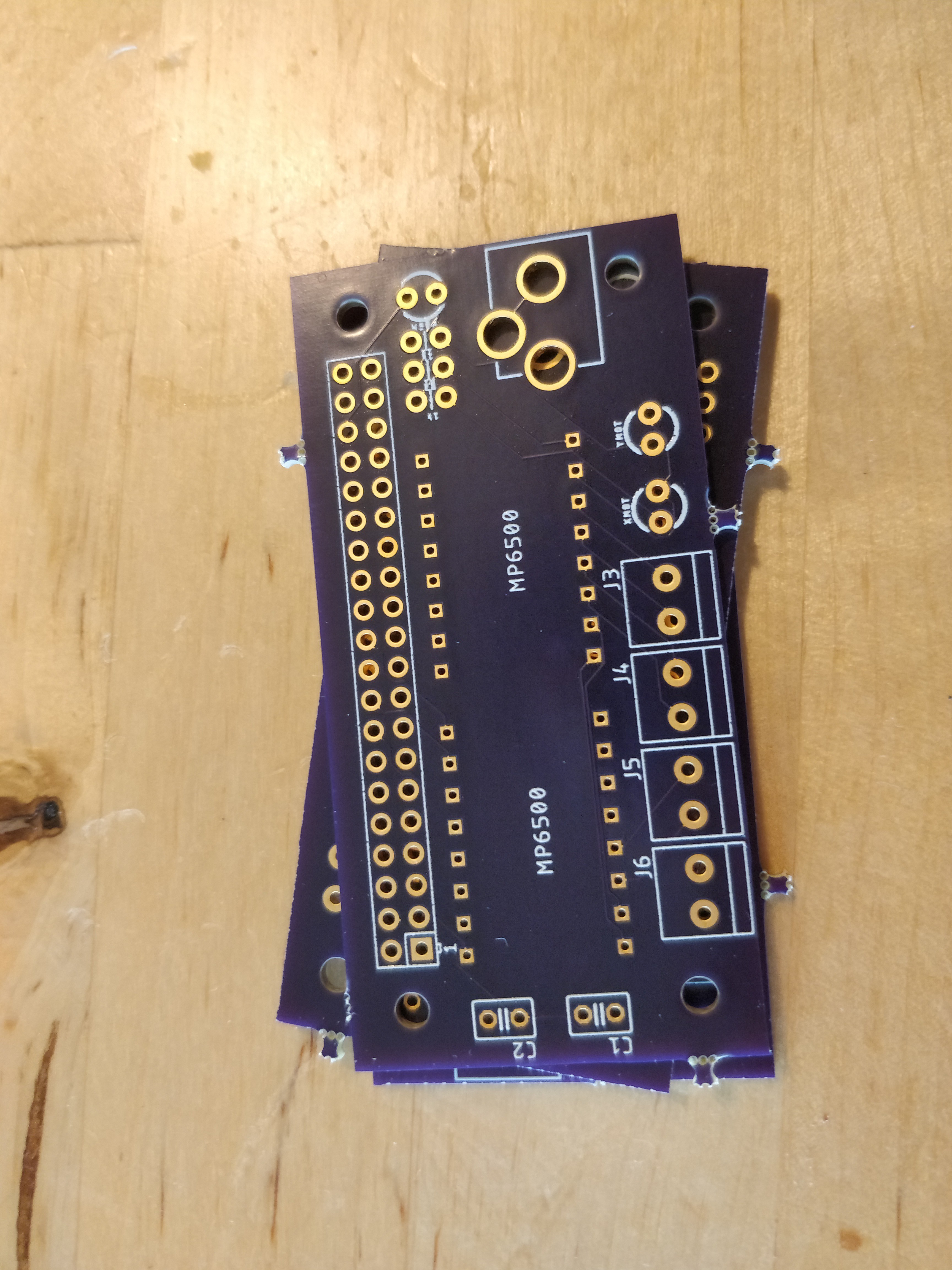
A lot of things have happened in such a short amount of time. The most exciting is that my oshpark boards arrived!! But as the title suggests, there is a minor problem with the through-hole size for the two stepper drivers... Which coincidentally were the only components I made custom footprints for :abashed: That being said, I should still be able to get this all soldered together for prototyping purposes :)
Ok it wasn't actually off-by-one. It was more like 0.5mm.
Also I realize that I completely missed out on the opportunity to add trendy silkscreen text. I guess the v0.2 board will be my grand stage for circuitry art.


A challenge for another day however...
Today, I am actually spending my time on prototyping a new base design which allows for "adjustable" belt tension. It uses the advanced technique of "jamming a bolt against the motor so I can adjust the distance"... Not something I plan to use as a final design, but it should help prove once-and-for-all whether the belt tension is actually the source of error in overall accuracy problems. Huzzah!
*6 hours later*
The new base design finished printing!! It didn't work out like I thought, but it provided me some valuable insight and a new direction.
Findings:
The belt causes tension in weird places. If it is pulled tight enough, the whole assembly bends awkwardly. This is of course fixable with more infill and stronger designs, but I think it is unnecessary and can be vastly simplified by simply driving the gear directly - sans pulley.
Edit: I will have to prototype this concept but I'm no longer so sure it is "better". There are some advantages to the belt driven mechanism which I would miss out on. Primarily among them, belts seem easier to mount and setup. But it's something to think about. My next update should be all about how this problem is fixed and no longer a thing to worry about.
Cheers! Until next time.
 Josh Cole
Discussions
Become a Hackaday.io Member
Create an account to leave a comment. Already have an account? Log In.