-
2 LUTs made with transistors in the simulator
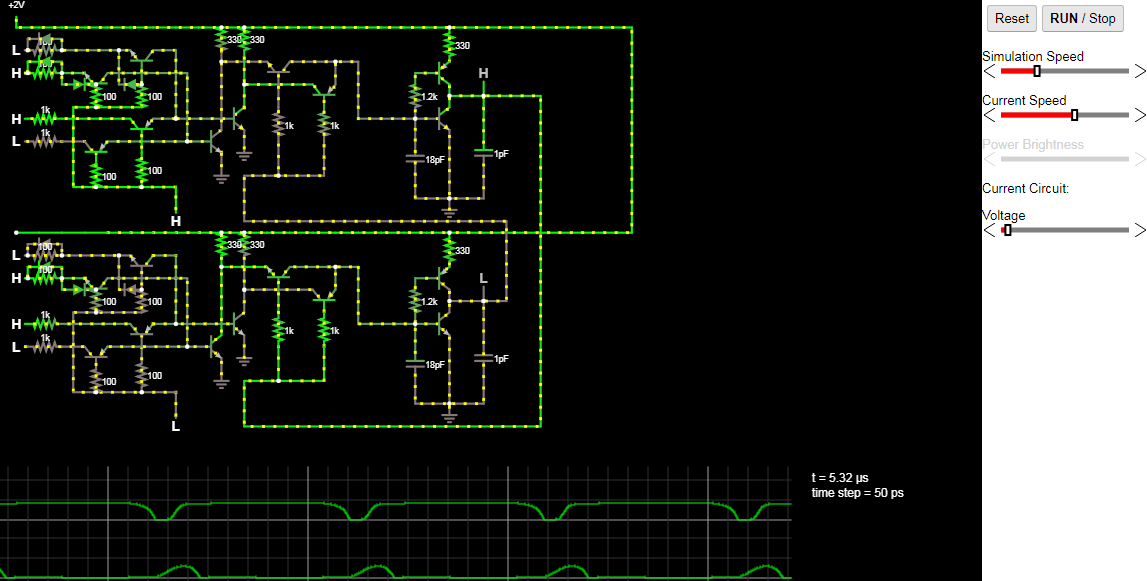
07/02/2018 at 23:17 • 0 commentsNormal voltage requirement is 2v, switches at about 600mV. All transistor betas are 100.
The capacitors are for simularing parasitic capacitance.
The above circuit is two LUTs connected to make a clock. One is configured as a buffer, the other as an inverter. The 8 inputs on the left tell the LUT what values are where. The inputs on the bottom of the LUTs are the address. The image above is at two volts input power.
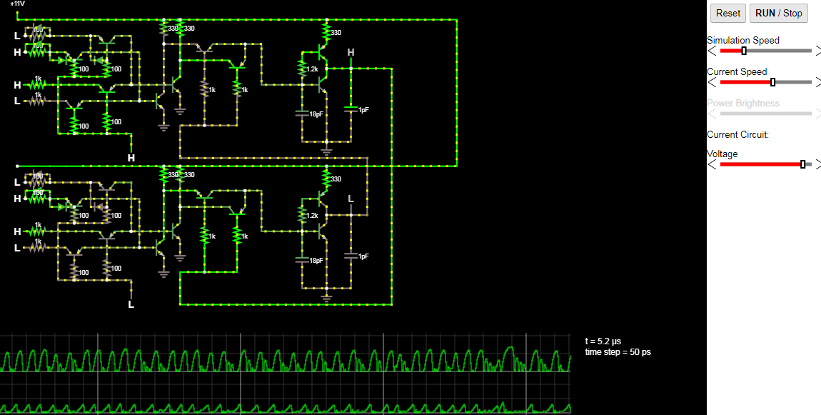
The circuit can take voltages up to about 11v before the logic stops working. This is at 11V to see how it switches right before the voltage that it stops working (between 11v and 11.16v). there is a lot of ringing for some reason, probably due to the small capacitors to simulate parasitic capacitance.
-
single FPGA slice (without routing)
07/01/2018 at 03:31 • 0 commentsI felt like building an FPGA slice, so I did.
Based somewhat upon Nick's Blog entry here.
![]()
Sorry for the bad photo, my phone has issues.
Essentially the bottom three ICs are 74hc595 (CMOS logic levels) for allowing an arduino to program the slice. The three ICs up top are two 8:1 MUXs and two D flip flops. The oscillator up top is connected to the D flip flops, so they always have updated values.
I used CMOS chips because I did not have enough TTL MUXs, even though I have plenty of every other TTL IC...
I may consider making many FPGA slices and connecting them together one day, with printed PCBs and such. Those would have DIP switches instead of 74595s because DIP switches are more fun to program.
Silicon
Random stuff I do with TTL, CMOS, and transistors. probably lots of programmable logic.
 Dylan Brophy

