-
SPINES Mote is on Internal Power
07/28/2018 at 17:34 • 0 commentsFollowing all the initial testing and debugging throughout the past weeks, it finally comes to the time to let the SPINES Mote run untethered.
![]()
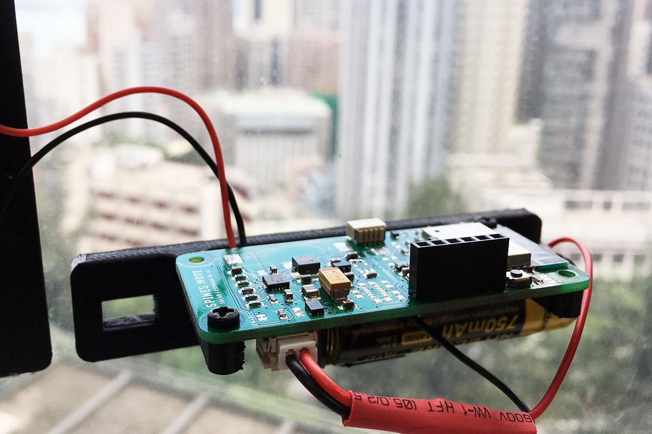
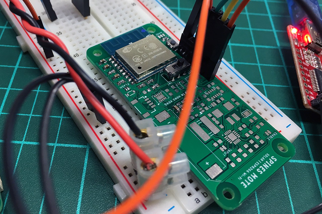
At the time of writing, the SPINES Mote pictured above has already been operating on its internal power (i.e., the attached 14500, or AA-sized, Li-ion cell rated at 750 mAh) for over 30 hours non-stop. The board is running a test sketch to take measurements from its onboard sensors, and transmit them to ThingSpeak every minute (consider this as a stress test to drain the battery). It keeps in the deep sleep mode for the rest of time to conserve energy, which should draw only around 100 µA from my back-of-envelope calculation for the worst case (without using the RTC for power gating), prior to implementing any of my planned optimizations.
Although a solar panel is attached to the board (see the top left cable), it is not actually helping recharge the battery yet: Putting the high duty cycle aside, I found a significant leakage current at ~6.4 mA even when the board is supposedly in the deep sleep mode!
---------- more ----------Of course, I have run some tests to trace the source of the leakage. In order to locate the leakage, I ran the tests on two boards, the untethered one shown above ("Board A"), and a separate board without the ESP8266, sensors, and battery fuel gauge ("Board B"). Here are some current measurements in several scenarios:
Description Current Drawn 1 Board A: ESP8266 and sensors active ~80 mA 2 Board A: ESP8266 in deep sleep; buck converter (i.e., sensor power rail) disabled ~6.4 mA 3 Board A: LDO disabled (with fuel gauge presumably on) ~56 µA 4 Board B: LDO disabled (i.e., completely "no load" with only the BQ25570 circuit left operating) ~1 µA 5 Board A: LDO enabled but no load ~220 µA 6 Board B: LDO enabled but no load ~100 µA Scenario 1 is nominal and pretty much what I expected according to the ESP8266 datasheet and past experience (80 mA is an average figure; there are spikes at >300 mA during transmission).
Scenario 2 is problematic: I never imagined it would reach the mA range. Deep sleep with a mA-range current consumption would virtually make self-sustainability via energy harvesting infeasible (unless using ridiculously large solar panel and battery pack).
Disabling the LDO regulator (currently enabled automatically using BQ25570's VBAT_OK signal) in Scenarios 3 and 4 revealed that LDO is actually the source of the leakage. Scenarios 5 and 6 further confirmed that enabling the LDO would cause a significant leakage even if there is no load attached to its output.
These test results forced me to resolve the RTC module issue (keeps crashing the ESP8266 in boot loop), such that I can make use of the RTC to disable the LDO and achieve sub-10 µA consumption during deep sleep (assuming that the fuel gauge is removed too). Some initial testing has indicated that the RTC issue was due to reset line jamming. Cutting the RTC module's reset trace brings it back to service. More to follow soon.
-
Preparing for Solar Cell Tests
07/25/2018 at 17:49 • 0 commentsThings get much smoother after fixing the ESP8266 I2C issue. While the RV-1805-C3 RTC module is interfering the ESP8266 and hence omitted for now (more details on this later), the rest of the PCB seems to be working fine: The environmental sensors are now fully functional, the LTC2942-1 battery fuel gauge is working (though this might be dropped ultimately due to its high current consumption, more testing needed), and most importantly, the energy harvesting circuit is somewhat charging the battery or supercapacitor.
Generally speaking, there are two things that you need to understand in order to build a self-sustaining, energy-harvesting system:
- Expense: How much energy does the system consume?
- Income: How much energy can the system harvest and make available for use?
Answering the first question is fairly straightforward: You can simply plug a current meter to profile how much power it is consuming at each stage (deep sleep, sensor polling, transmitting, etc.), and derive an upper bound for this.
On the other hand, determining (or predicting) energy availability is difficult, especially for uncontrollable (though somewhat predictable) energy sources like solar. The software part of this project is meant to address this problem, but that will be a long story to tell in some future posts. For the time being, I will need to characterize the hardware capabilities with different types of solar cells that I have:
- IXYS KXOB22-01X8F (This is the one that can be placed on the PCB. I do not really expect it to be useful for the ESP8266-based SPINES Mote, but I thought that it would be interesting to evaluate what it can do for some future lower-power SPINES variants.)
- Seeed Technology 0.5 W Solar Panel
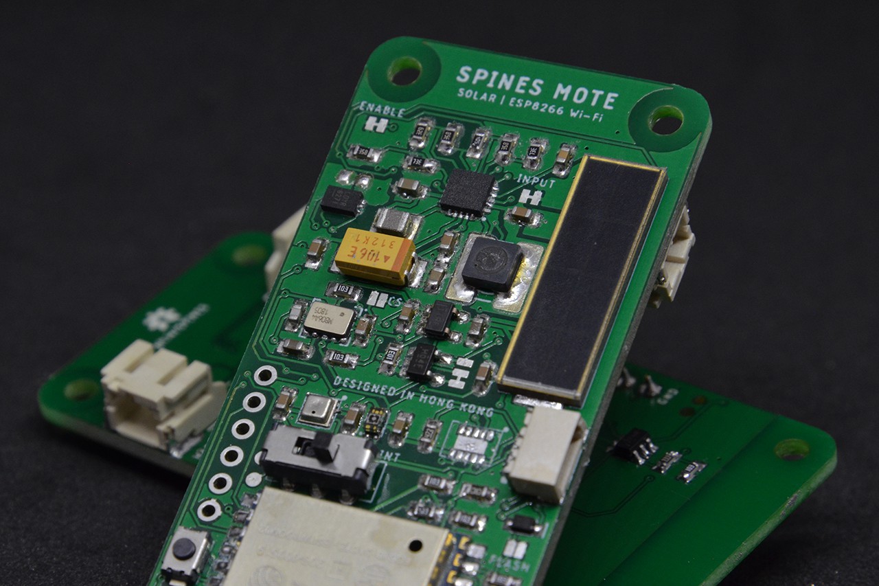
- Some ultra cheap solar panels "rated" at 1 W (as shown in the picture below)
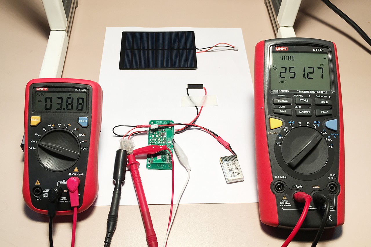
I have just set up a halogen lamp test stand to establish the best-case scenario. This measures the charging current (with the multimeter on the right; the left one is probing the battery voltage) to a 240 mAh LiPo battery via the BQ25570 power management IC.
![]()
With the halogen lamp turned on (measured at 300 lux with an iPhone app), the KXOB22-01X8F can deliver around 250 µA to the battery, while the 1 W solar panel can achieve up to 8 mA.
I am going to test how well (or bad) the charging goes for these solar cells in more realistic outdoor and indoor (thanks for the mention in the Hackaday newsletter!) scenarios in the next few days. Hope the weather will turn better for outdoor tests. Stay tuned.
-
Resolving the ESP8266 I2C Issue
07/23/2018 at 13:33 • 0 commentsTL;DR: Bad soldering. A really dumb mistake that I haven't discovered it until observing an anomaly on the oscilloscope a week later.
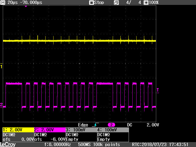
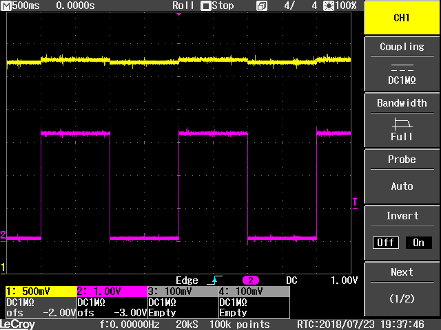
Spent several more days on diagnosing the I2C issue with the ESP-WROOM-02 module. Finally, I managed to get access to an oscilloscope. I hooked up the SDA (CH1) and SCL (CH2) lines, and the root cause became obvious: The SDA line could not be driven low!
![]() ---------- more ----------
---------- more ----------At this point, I was skeptic if the boot pins (i.e., IO0, IO2, and IO15) cannot be used as GPIO (and hence the bit-banging I2C), so I tried running a simple sketch to toggle IO2 (CH1) and IO15 (CH2) as shown below.
![]()
Obviously there was something wrong with IO2. I repeated the same experiments on an ESP-12F breakout board, and both the toggling and I2C (IO2 as SDA and IO14 as SCL) functioned flawlessly.
IO2's waveform tells that the firmware attempts to drive the pin low, but something resists strongly. Then I looked for a short between VCC and SDA. Bingo.
Fixed the short, and got the BME280 and VEML6075 sensors working. After all, I could not trace the origin of the short, but my bet is on some tiny DFN or LGA pads...
-
More Testing on ESP8266
07/20/2018 at 14:55 • 0 commentsI have done some more SMD rework and tests to try to find out the root cause of the weird behavior on the ESP8266 module described in my previous project log.
It turns out that the issue (probably) has nothing to do with soldering, instead, the I2C bus is causing problems: The two "problematic" boards were resurrected after removing all I2C peripherals, and the same issue appeared on the freshly soldered ESP8266 test bed once I attach any I2C device to it.
Further investigation using my NodeMCU and old ESP8266 breakout boards (also based on the ESP-12F module) revealed that this is more like an issue related to the ESP8266 Arduino core's Wire library implementation, as the bit-banging I2C (note that there is no hardware I2C on ESP8266) occasionally causes strange failures (watchdog reset, not detecting some devices with an I2C scanner sketch, etc.) on these boards too.
At the moment, I do not really have a conclusive explanation on the root cause. Since the I2C bus is essential to the SPINES design, I hope that I can figure out a workaround for ESP8266 in the next few days (or I will need to move on to another IoT module, maybe one with LoRa or BLE):
- Revert to an older version of the Arduino core
- Add some delay(1) to the Wire library function calls
- Any other suggestion?
-
Initial Testing: Unexpected Issues
07/14/2018 at 09:42 • 0 commentsI ran some preliminary tests on the energy harvesting and ESP8266 functions with the two soldered boards yesterday.
The energy harvesting part, especially TI BQ25570 power management IC circuitry (though proven in several previous projects), works pretty much as expected. Solar power generation with either the onboard KXOB22 solar cell (this addition to the PCB was initially inspired by the TSEM project, and I found out that this is the cheapest option on Digi-Key for a similar form factor) or an external 0.5 W solar panel appears to be working.
I will do more testing on the power generation later. It has been raining in Hong Kong for several days, and my halogen lamp burned out...
I believed that the ESP8266 would be the most straightforward part in this project. But the strangest thing so far happened on it.
---------- more ----------I have created at least five ESP8266 custom boards using the ESP-12F module in the past few years, all programmed using the Arduino core. They worked flawlessly most of the time. However, this is my first attempt on the ESP-WROOM-02 module (note that it has a different pin-out and only a 2 MB flash). I picked this newer variant this time because of its slightly "shorter" dimension, and the absence of an onboard LED which is a bad thing for low-power applications.
After powering the board to external 3.3 V supply, I tried to program it with Arduino as usual: The uploading works, but the application code does not run. The module keeps spamming the UART console with the error messages below. I tried to add extra decoupling capacitors, to use literally every combination of board configurations in Arduino IDE, but the problem persists on both boards.
ets Jan  8 2013,rst cause:2, boot mode:(3,6)

load 0x4010f000, len 1384, room 16
tail 8
chksum 0x2d
csum 0x2d
v614f7c32
~ld
Then I flashed a MicroPython image, and it worked on both boards. Testing on the MicroPython REPL did not indicate any significant problem with the microcontroller. Weird.
Before thinking about abandoning the design and reverting to ESP-12F, I hand-soldered a third board to give it a last shot.
![]()
This time it works with the Arduino core! Perhaps the reflow soldering somewhat damaged the ESP-WROOM-02 module, in particular the flash chip (given the checksum error messages), or I just had luck and got two faulty modules in a row? Anyway, I will avoid reflow soldering these kind of chips.
-
Reflow Soldering
07/13/2018 at 16:44 • 0 comments![]()
Finally I gathered all needed parts today. Assembled two prototypes with a reflow soldering hot plate (yes, there are solder bridges and things need to be fixed). The board looks good so far, despite the oversized inductor footprint...
I will start testing them tomorrow. Meanwhile, please enjoy this timelapse video of the reflow soldering process!
-
PCBs Arrived
07/11/2018 at 09:50 • 0 commentsCollected the PCBs, stencil, and most of the parts yesterday. Now waiting for the 0603 passives and I can start soldering...
![]()
-
Modular Design Concept
07/08/2018 at 17:20 • 0 commentsSPINES Mote embraces modular design. Despite being a highly integrated single-board sensor node, the board is composed of three high-level functional blocks, as illustrated in the figure below:
- Energy Harvesting and Power Management Hardware: This block is meant to be reused across multiple designs. I will have a separate post to talk about this soon.
- Onboard Sensor Suite: My reference implementation includes three sensors (BME280, CCS811, and VEML6075), as well as a Qwiic expansion port for connecting external I2C sensor modules. This block can be easily replaced when customizing the PCB design.
- IoT Module Variant: The "variant" system is the core of SPINES' modularity. Please see below for elaboration.

IoT projects have heterogeneous requirements, and they often need to utilize different types of wireless networks and application processors. In SPINES, this purple section is designed to be "swappable": Not physically swapping in another hardware module, but you can very easily integrate your own design block into a custom SPINES Mote PCB. Apart from the reference designs of complete sensor nodes, I am going to release "template" design files such that you can easily insert your favorite combination of microcontroller and radio (STM32, RFM95, ESP32, nRF series, etc.), and fabricate your unique flavor of SPINES Mote with its compact form factor.
The preview version of SPINES Mote's schematic (solar-powered ESP8266 variant) is shown below. Note that the "IoT Module Variant" depicted above corresponds to the "Application Processor" building block in the schematic. You can create your own SPINES Mote variant just by pasting your design block into the schematic, and connecting several traces in the PCB layout!
")
The EAGLE design files will be released as soon as I receive the boards and finish verifying their basic functionalities. This should happen in the next 3 to 4 days.
-
First Design
07/04/2018 at 17:08 • 0 comments![]()
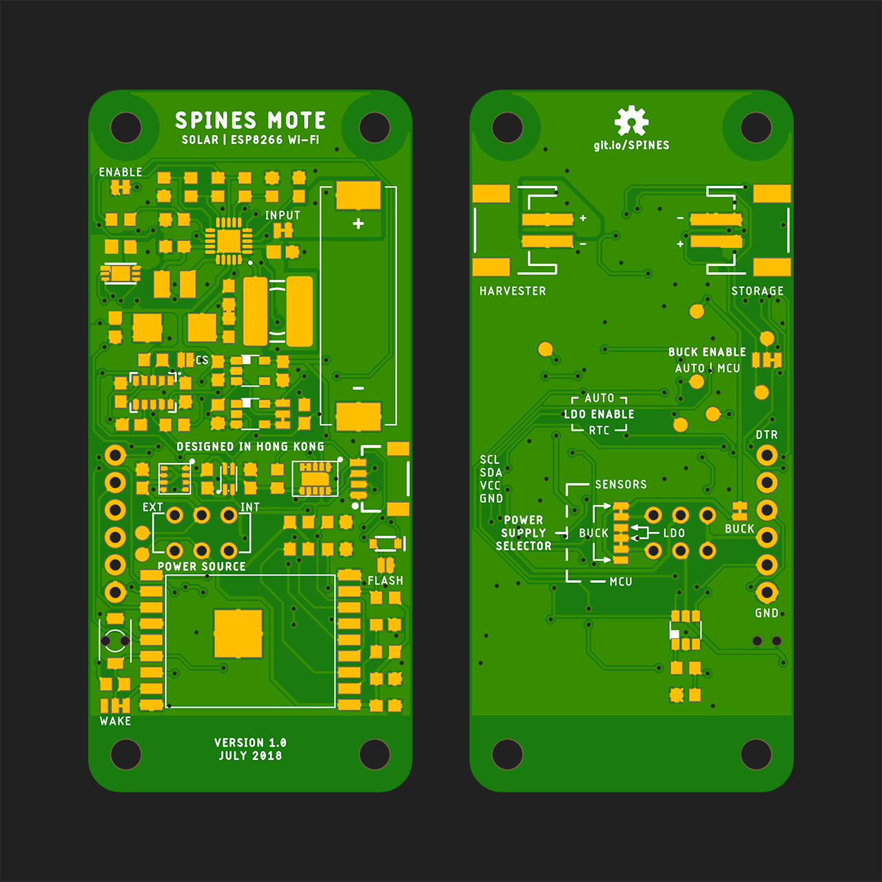
The first SPINES Mote design features a solar-powered ESP8266 (admittedly, powering a power-hungry Wi-Fi radio with a tiny solar cell might not be the best idea; a LoRa version is coming soon) with three onboard environmental sensors:
- BME280 for temperature, humidity, and pressure
- CCS811 for volatile organic compounds (VOCs)
- VEML6075 for UVA and UVB light
The first batch of PCBs is now being fabricated on PCBWay's factory floor. While waiting for the PCBs and parts to arrive early next week, I will introduce the modular design of SPINES in the next couple of days.


")