Mile
Mile-
Energy scavenger as Temperature and Humidity sensor
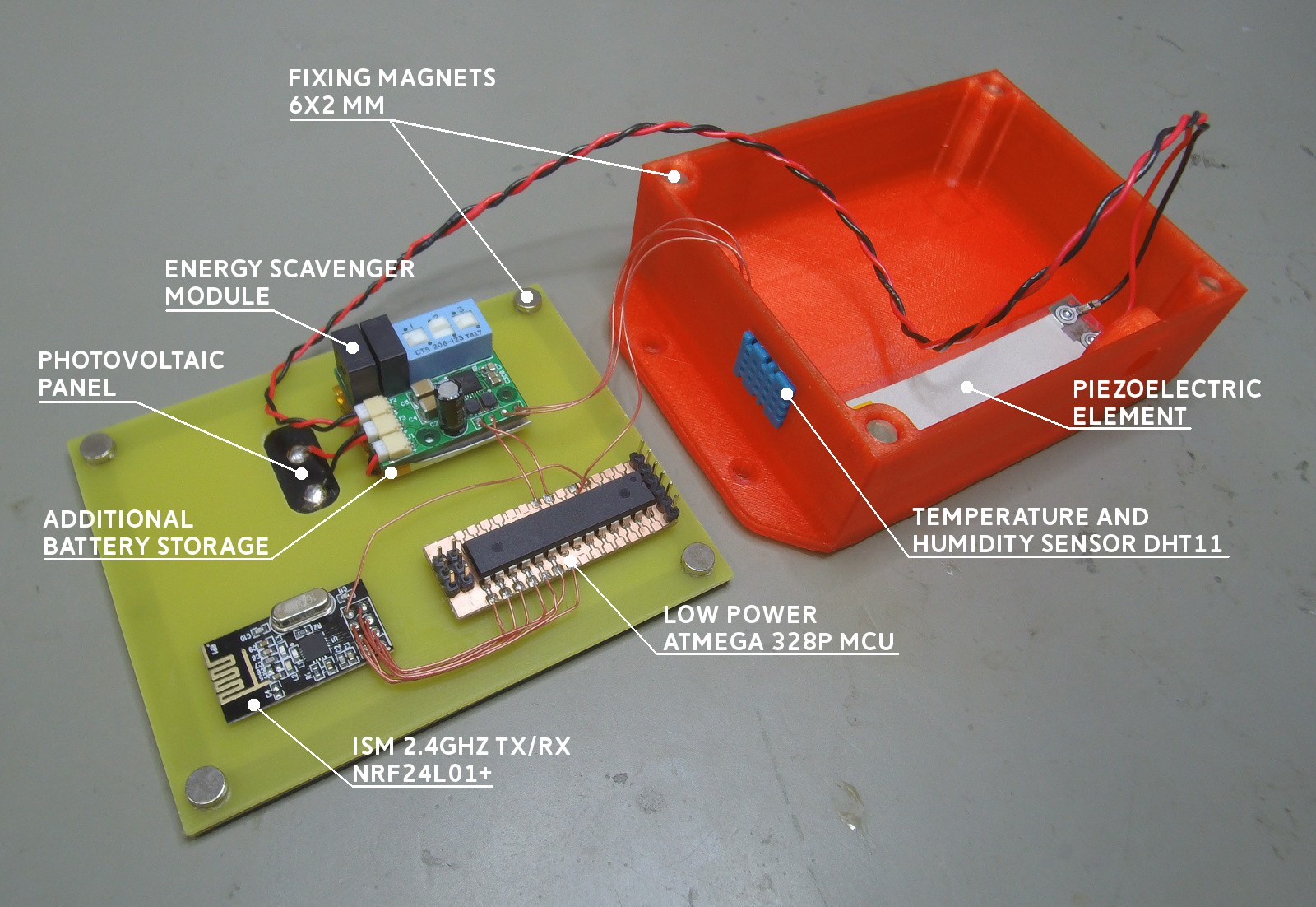
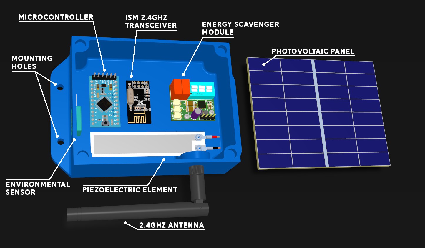
07/15/2018 at 21:28 • 0 commentsImage below shows Energy scavenger module in 3D printed enclosure. There is also ATmega328P arduino compatible board optimized for low power operation(only basic components, running on internal oscillator), ISM 2.4 GHz RX/TX module(NRF24l01+) and humidity and temperature sensor(DHT11). Energy is harvested by piezoelectric element and photovoltaic panel on top of the enclosure. There is also hole for external clip-on antenna but for running first tests long range capability is not needed.
![]()
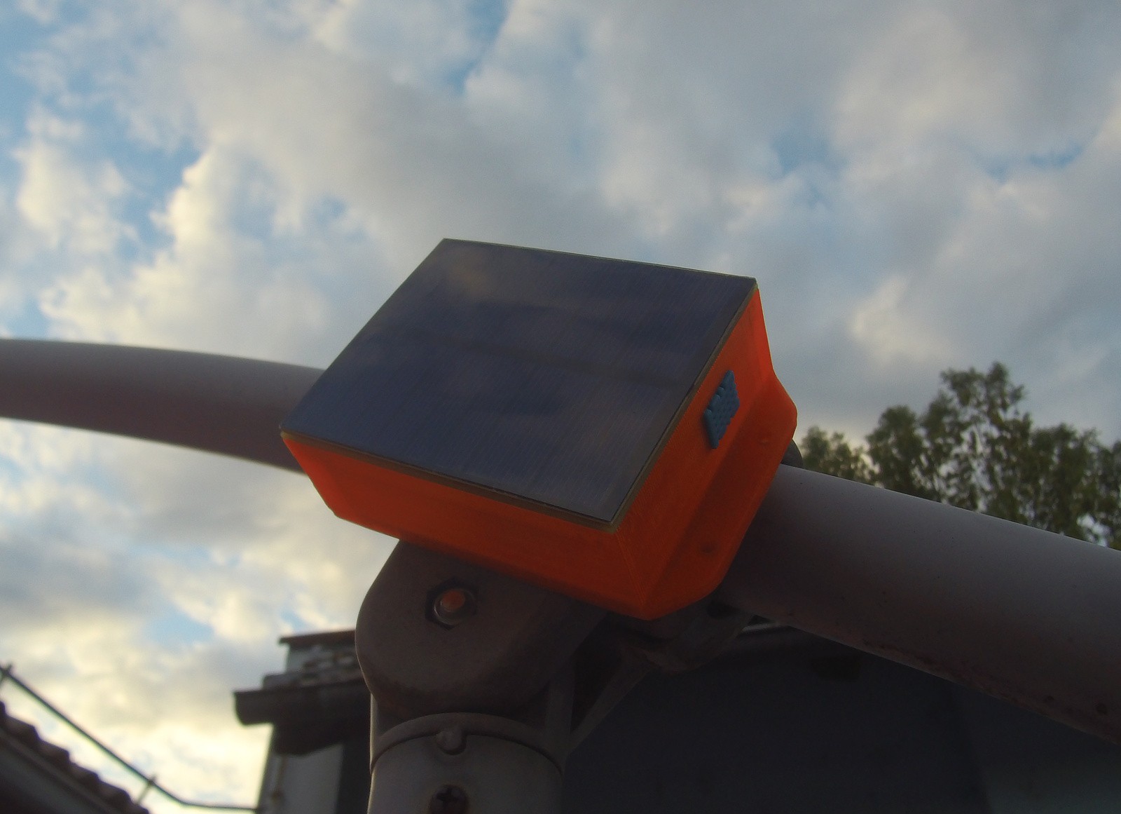
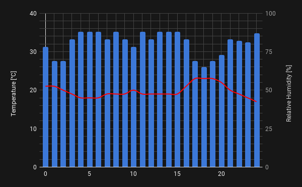
Device in this configuration is located in backyard and is monitoring temperature and humidity and sending it to nearby node(located in house), periodically every 60 minutes. Data is logged and then plotted. Since there is not much data to transmit and distance from mode is not more than 50 meters low data rates of 250kbps and transmitter output power of -18dBm are more than enough here. With this specs device consumes around 20uA in idle and around 7mA when transmitting.
![]()
As it can be seen from from measurements conducted on photovoltaic panel in previous project log, panel can provide more than enough power for 24/7 operation.
![]()
-
Energy scavenger module assembly
07/14/2018 at 14:29 • 0 commentsVideo below shows process of PCB assembly. Since there is small number of components and most of them are TH, I decided to save on stencil and apply solder paste by hand. This approach is not optimal for small pitch packages because it require additional rework to remove formed short circuit bridges. In the end, because there is only one small pitch component it will be more time efficient than soldering components one by one.
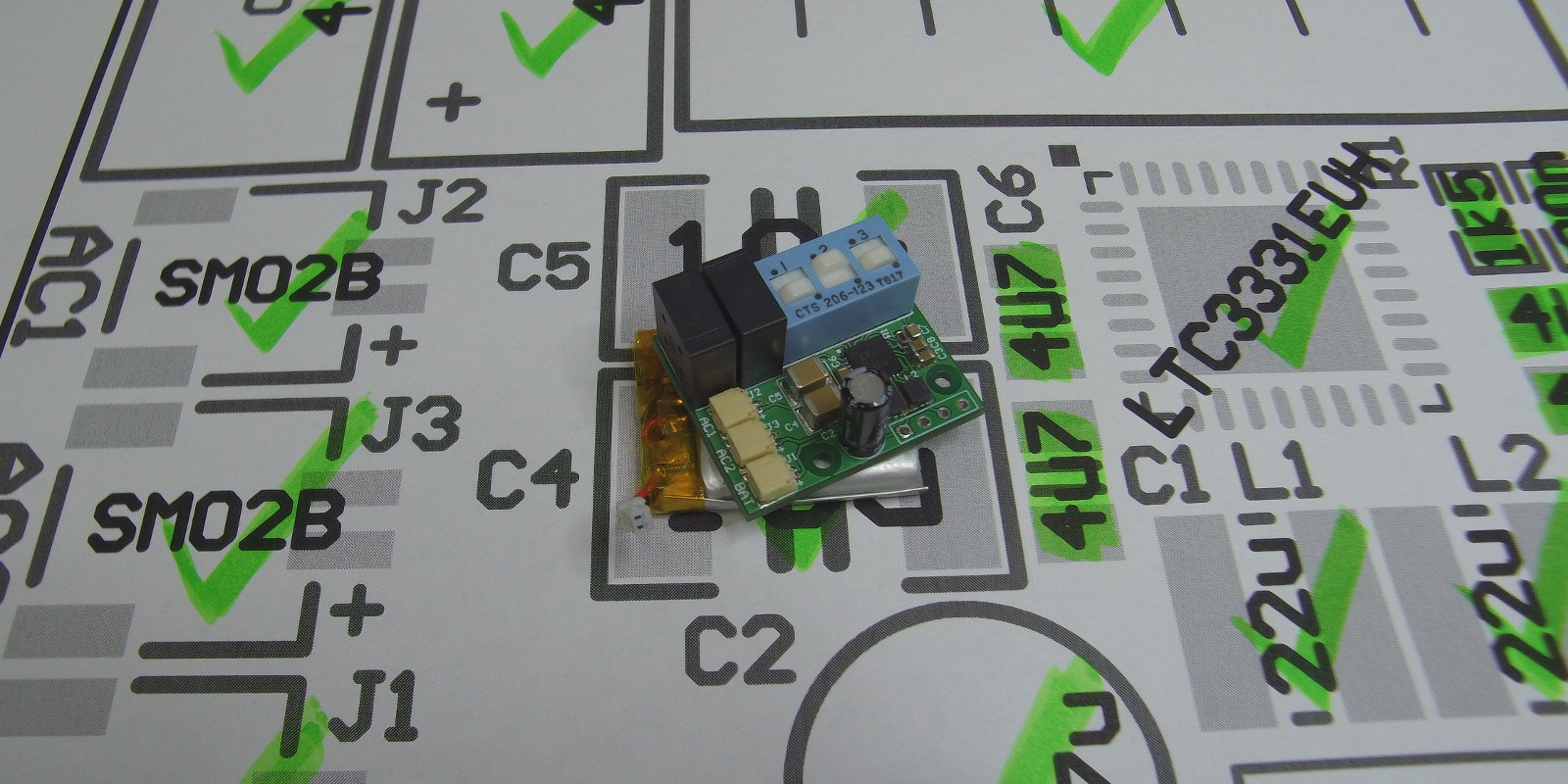
Assembly drawing makes placing components easy, fast and decreases chance of placing component in wrong position and ruing your day.
![]()
Enclosure is 80x100mm so that it accommodates photovoltaic panel of the same size. It can be mounted using magnets(fast and less labor intensive) or screws(more secure option). Cover lid with photovoltaic panel is held with magnets. Inside, there is place for custom electronics, sensors and additional external antenna to increase signal range. Since enclosure is 3D printed and used just as proof of concept it does not have proper IP protection against environmental effects, therefore alternative protection of electronics is needed.
![]()
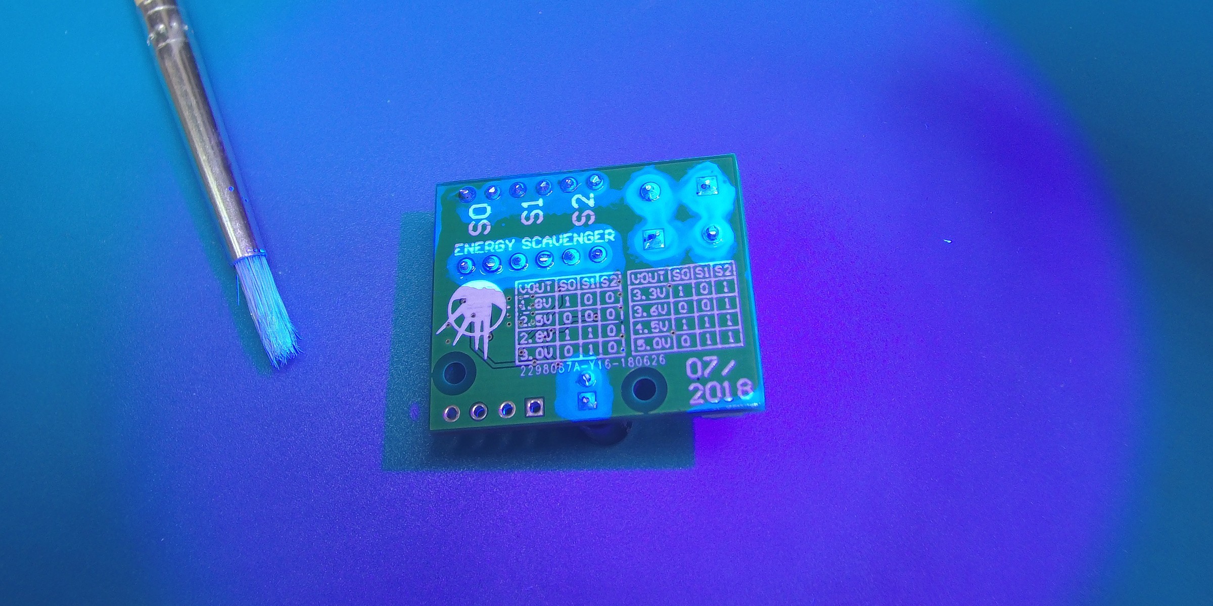
After assembly module is conformally coated to protect solder joints from corrosion. Corrosion may occur when module exposed to moisture and humidity. This is necessary since module will be enclosed in 3D printed prototype enclosure which can't properly protect against environmental effects.
![]()
-
PTPM Energy Scavenger Module
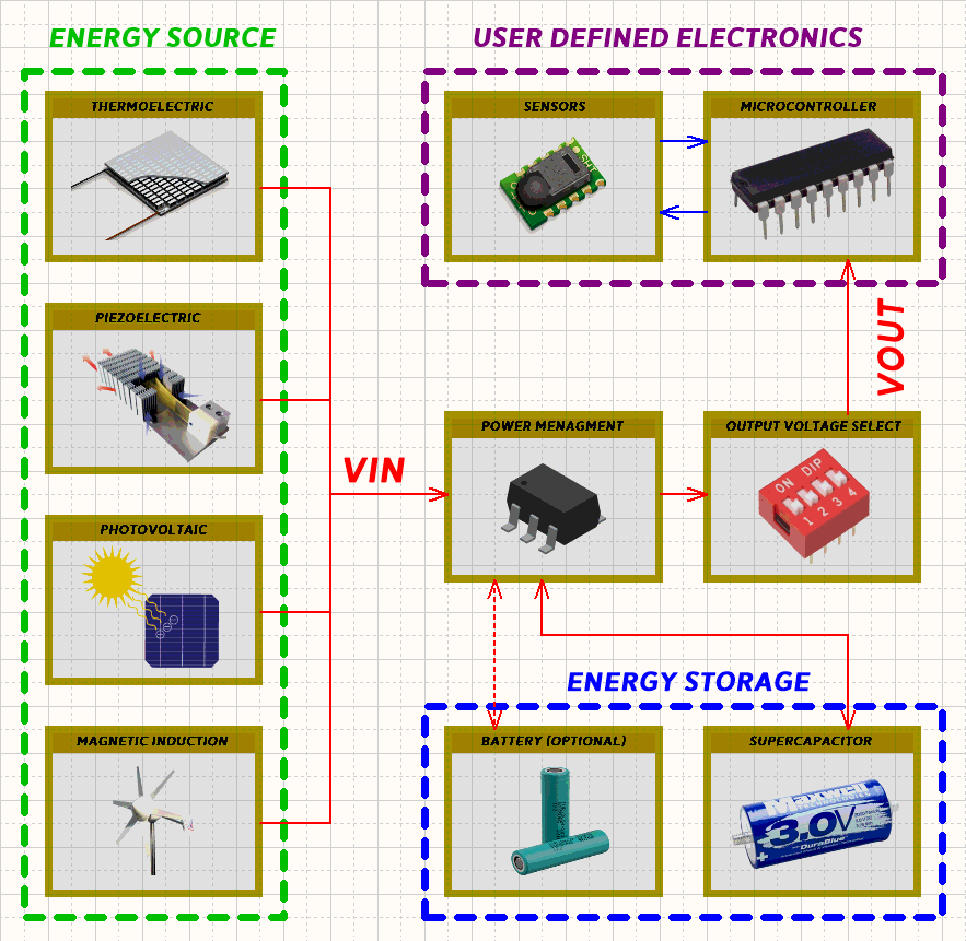
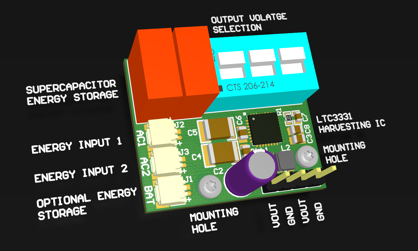
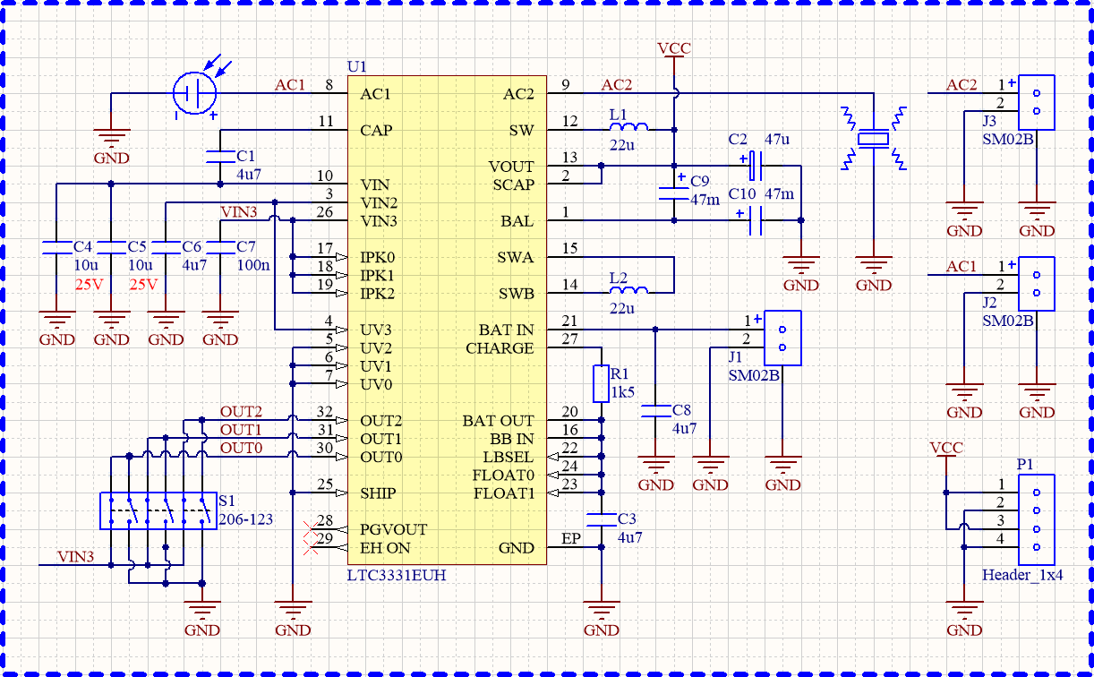
07/10/2018 at 18:53 • 0 commentsPTPM Energy Scavenger is envisioned as module that can harvest environmental energy from wide range of sources. To bring this concept to life versatile IC solution is needed. One such is Linear technology LTC3331, energy harvesting PMIC that can harvest energy from photovoltaic cells, TEGs, Piezoelectric elements and induction generators. Harvested energy is stored in on-board supercapacitors or external(optional) li-ion battery. Module can be divided into four parts:
![]()
- Energy harvesting input(AC1, AC2): Internally connected to low voltage drop full bridge rectifier and step-up/down switching converters.
- Energy storage - optional(BAT) and on-board (C10, C9): External battery can be used for high power consumption applications or if not needed it can be excluded to save on cost and space.
- Output voltage selection(S1): SPDT switch for adjusting output voltage from 1.8V to 5V.
- Output power supply(P1): Pin header with two Vout and two Gnd pins.
![]()
Resistor R1 is used to adjust battery charging current. Equation for calculating charging current is: Icharge = 1.6 / (R1+60). Charging current should be in relation to average available harvestable energy in surrounding environment.
![]()
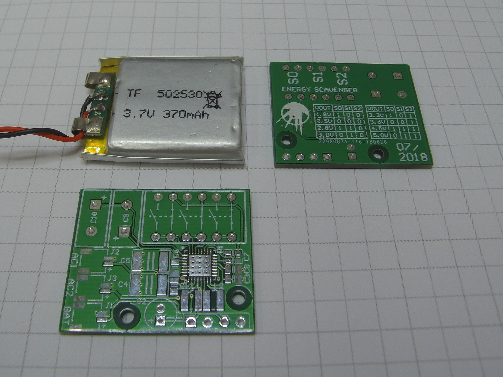
Main goal while designing PCB was to achieve smallest size as possible to reduce the cost of fabrication while still being relatively easy to assemble. PCB is 25x30mm in size so that it can be laid over li-po battery of same dimensions. PCB can be secured with two 1.8mm screws or with double-sided tape. Bottom picture shows fabricated PCB (bottom and top side):
![]()
-
Evaluating Photovoltaic panel and Piezoelectric element
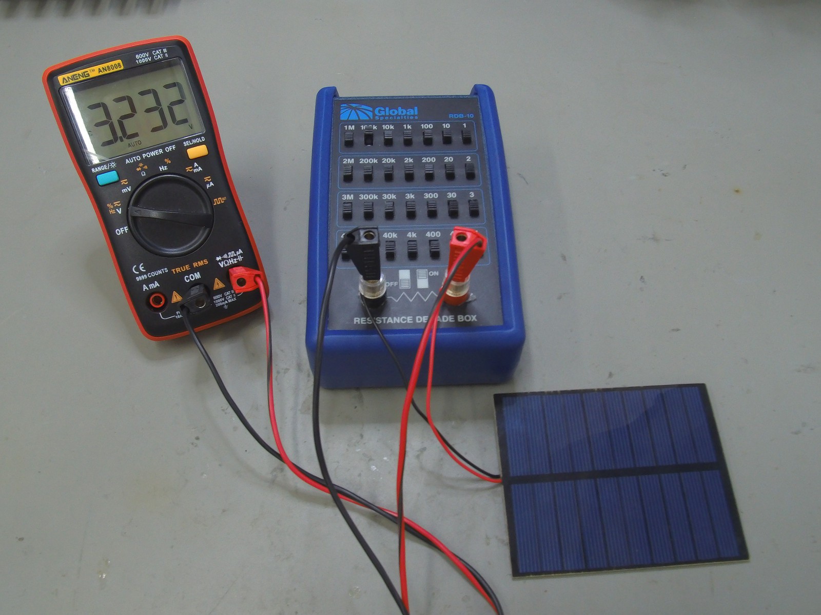
07/04/2018 at 19:59 • 0 commentsFollowing measurements will evaluate effectiveness of photovoltaic panel(100x80mm) and piezoelectric element(PN:LDT2-028K/L) in energy harvesting application. Photovoltaic panel is tested indoor at illuminance of about 150 lux and outside in full daylight(~10000 lux).
![]()
Test setup includes photovoltaic panel, DMM and resistor decade box. ![]()
![]()
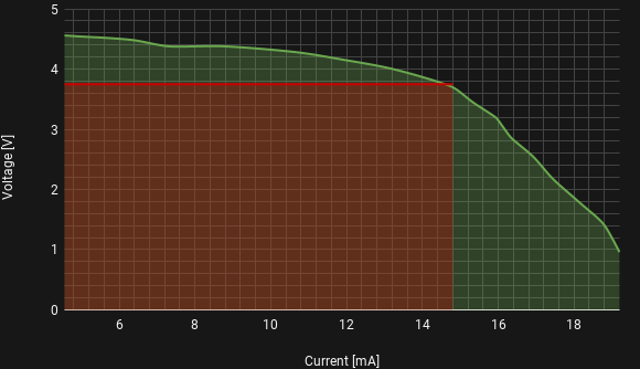
Conclusion: Indoor, maximum power output(red marked area) achieved with input 2.2V@440uA while outdoor with input 3.8V@13.8mA. Average current draw of the device should be around those values.
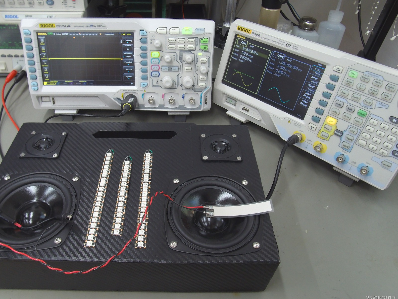
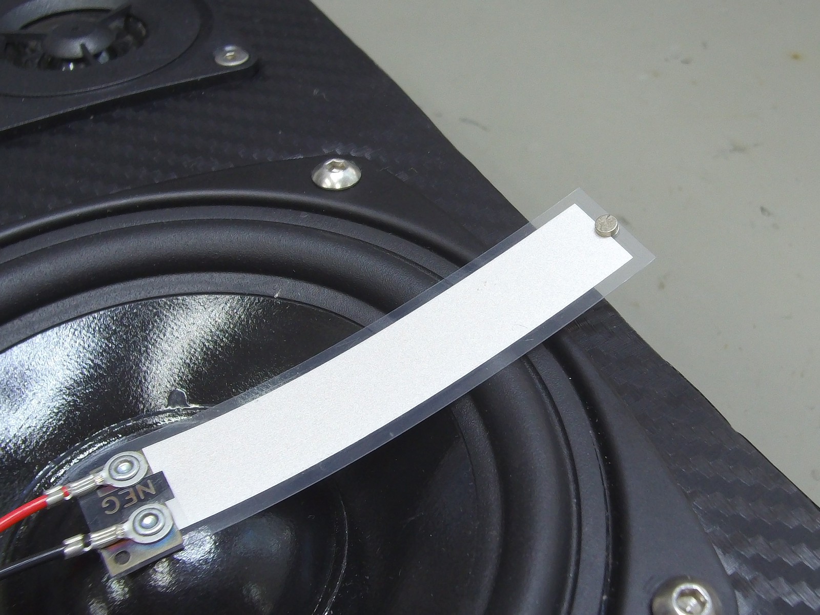
Piezoelectic element is attached to speaker membrane and driven with 50Hz sine wave to emulate vibrations produced by operating machinery. Small mass(magnets) are added to tip to see its effect on output voltage. Magnets used are: 2x1mm - 2pcs(0.04g), 3x1mm - 2pcs(0.09g), 5x1mm - 2pcs(0.26g).
![]()
Test setup includes piezoelectic element, speaker, audio amplifier and function generator. ![]()
Example of magnet used for adding mass to the tip. ![]()
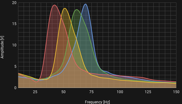
Resonant frequency with no tip mass, 0.04 grams, 0.09 grams and 0.26 grams. Conclusion: Adding bigger mass to the tip dampens the element(lowers the resonant frequency). For maximum power output tip mass coresponding the resonant frequency of the vibration source should be chosen.
PTPM Energy Scavenger
Photovoltaic, Thermoelectric, Piezoelectric, Magnetic induction Energy scavenger