 Torbjörn Lindholm
- Now MOSFETs have current-limiting resistors which can be used if you have MOSFETs with lower gate voltage (1.45V etc). By default the board aims for 2mA with voltage of 1.3V (R11 and R12 is 1K)
- If you have MOSFETs with 3.3V gate voltage, you can simply add 0R jumper resistor or bridge the pad with a wire.
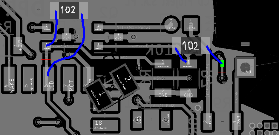
- If you happened to order the board before it was fixed, refer to this picture:
![]()
Cut the traces with red lines, scrape the part marked with green and wire the resistors up as shown here.
- Crazy value for pull-down resistors has been fixed. (R6 and R7 is now 10K)
- Crazy value for LED and motor current limiting resistors has been fixed. (R8 is 82R and R9 is 10R)
- Board layout has been tweaked slightly
- Overall board size has been decreased for ease of manufacture
This project has been going on for a really long time and I hope all this was for something...
(Also I cannot finish the prototype boards because I did not receive all the parts)


Discussions
Become a Hackaday.io Member
Create an account to leave a comment. Already have an account? Log In.