Close
0%
0%

Electron Bucket - extreme power management module

When every last nanoamp matters. Powering projects even from LEDs

Similar projects worth following
The ambient energy sources typically have very low power outputs that cannot run a project directly. Therefore one needs to collect the power over time and store it in a capacitor, or a battery, before it can be used.
This project implements an ultra low power management module that will allow utilization of very low power sources, such as solar cells in low light indoor conditions, ambient RF harvesting, piezoelectric generators, etc. Generally any source that has very high impedance and voltages above 2V can be used in combination with this power management module to power intermittently a low power project.

Let's say you are making a low power device, for example a nice sensor node for your smart home, and you don't want to use batteries. You want to use some ambient power source, for example indoor solar cells or ambient RF. The challenge is working with extremely low levels of power available in residential homes. For example on walls of a living rooms or in bedroom there is about 10-30lux or even lower illuminance. A cheap AM-1417 solar cell would produce around 500nA at 2V under these conditions meaning there isn't a lot of current to go around. 

Therefore we need to collect those nanowatts into a storage capacitor, charge it to a threshold level and then activate the load once there is sufficient energy to run it. The minimum amount of power we can collect is going to be driven by the consumption of the circuit performing the monitoring of the storage capacitor. 

This project is demonstrating a power management module that can be used to interface a very high impedance source, collect those precious nanowatts and then power the load. The circuit monitors the voltage of the storage and when the threshold voltage is reached it activates the load. But wait, there is more! Once the threshold is reached, and the load is connected, this circuit will disable the voltage monitoring part allowing even lower system consumption. This is especially important in two scenarios: first, if the load has a low power mode that has lower power consumption than the monitoring circuit thus making it better to keep the load connected instead of the voltage monitor. Second, if the voltage monitor has a very high current consumption after it has detected the voltage level. 

The circuit has a voltage monitor reset input that will disable the output and restart the process of voltage monitoring if the load should be disconnected once its task is done.

The heart of the system is the voltage monitor. The power consumption while initially charging is going to depend on the choice of the voltage detector circuit. The lowest power consumption I have achieved is using this circuit as a voltage detector. Its interesting how this voltage detector circuit is based on standard BJTs and that it uses LEDs as a reference for voltage detection. However, there is one big drawback. Once the voltage on the input reaches the voltage threshold the circuit's current consumption spikes to several mA which will drain a small input capacitor in a blink of an eye. Therefore, the rest of power manager is  there to use the voltage detector as a trigger and then disconnect it, thus preventing the massive energy loss. Furthermore, the voltage detector circuit on its own would discharge the input capacitor until it reaches 0.6V which is a waste as most electronics stop operating a bit below 1.8V.

As LEDs are used for voltage reference the selection of threshold voltage levels is limited and the threshold value is going to be dependent on the environmental conditions. If a precise voltage control is required another type of voltage detector can be used.  For example a Torex semiconductor XC6135, XC6136 or an Intersil ISL880xx series of voltage detector circuits.

In the examples shown in the project log it can be seen how the high input impedance of the circuit comes into play when using low power sources such as solar cells indoors, ambient RF or even using LEDs. I have successfully powered a Bluetooth low energy sensor that measures temperature using some of the previously mentioned power sources.
ElectronBucket v1.0.sch

EAGLE schematic of the circuit

sch - 793.95 kB - 07/15/2018 at 11:49

Download

ElectronBucket v1.0.brd

EAGLE PCB design of the circuit

brd - 97.13 kB - 07/15/2018 at 11:49

Download

ElectronBucket-Schematic.pdf

Schematic of the circuit in PDF

Adobe Portable Document Format - 20.46 kB - 07/15/2018 at 11:48

Preview

  • Electron Bucket Power Management PCB

    milojkovicmilan07/15/2018 at 11:47 0 comments

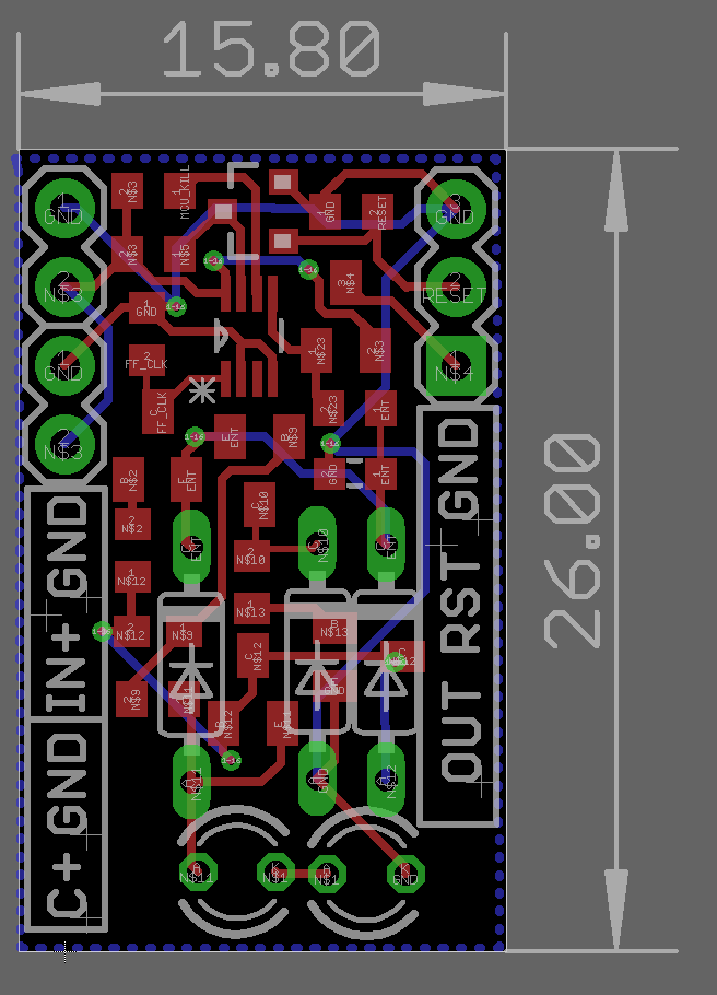
    The first version of the PCB for the power management is done. 

    The PCB has been designed to be small size and compatible with a breadboard making it easy to prototype and incorporate in designs. 

  • Nearly powering circuit using suspended alu foil

    milojkovicmilan07/15/2018 at 09:07 0 comments

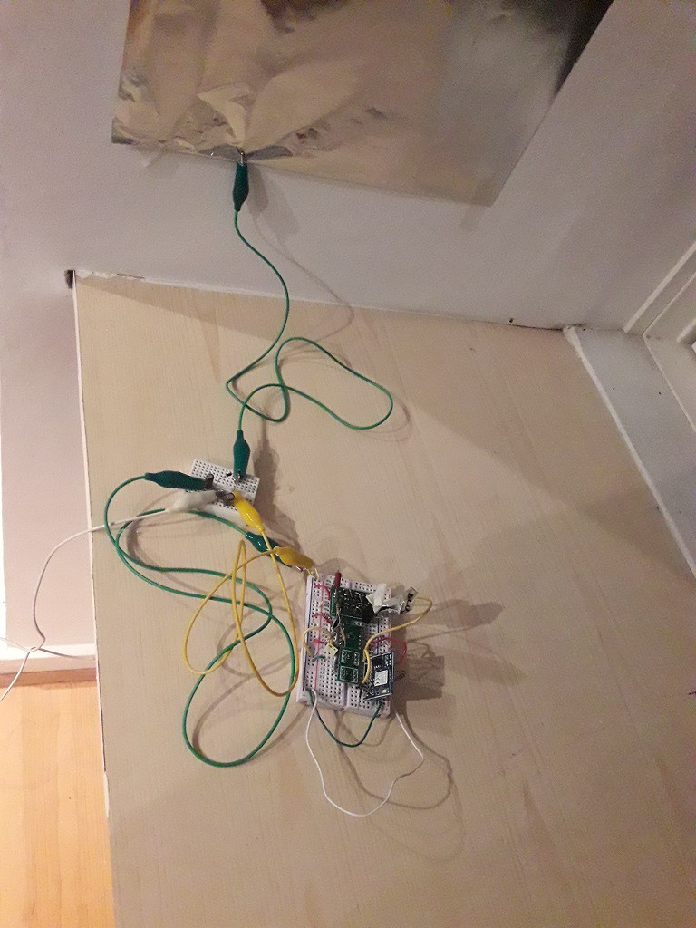
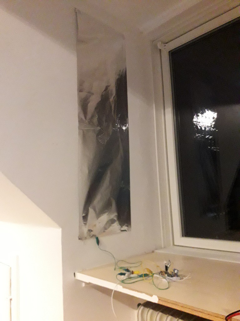
    On the pursuit of finding fun and unusual power sources to run the electronics with the help of the power management board I have looked into using the power from the air similarly how a crystal radio works without a power source. 

    Although I have made a small alternation to the crystal radio concept. Namely, instead of a long antenna and a matching circuit to tune to a station I have used a large piece of aluminum foil. 

    Ultimately the setup was consisting of an aluminium foil connected to one input of a voltage doubler circuit, that acts as a rectifier, and the other input to the voltage double was connected to the central heating system acting as ground. The output of the voltage doubler was connected to the input of the power management. On the output of the power management circuit was a Bluetooth low energy node set to measure the temperature. 

    This setup was left over night to charge as the amount of current available was expected to be very small. In the morning I have measured 2.6V. This voltage is just at the border of triggering leading me to believe that there just wasn't sufficient current to make the circuit push over the threshold. 

    Although this didn't work out so far increasing the antenna and maybe tweaking the circuit a bit more would allow powering a system from a very simple power source. Stay Tuned

  • Powering Electronics using LEDs

    milojkovicmilan07/14/2018 at 14:29 0 comments

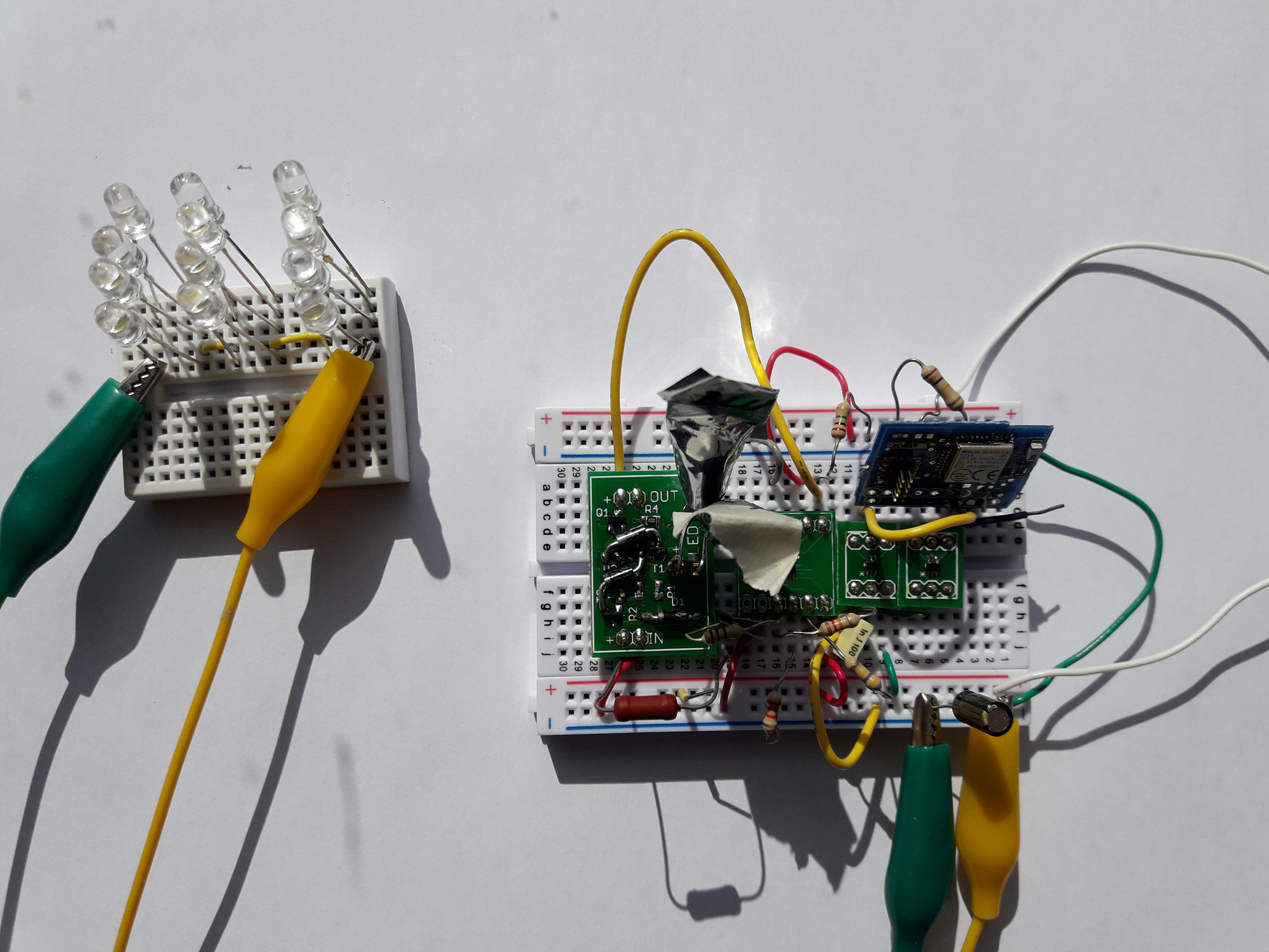
    As the input impedance of the power management circuit is extremely large it is possible to power projects from unusual sources. 

    In this example I have used a series of LEDs to power a Bluetooth low energy board that transmits temperature measurements. When hit by direct sunlight the LEDs produce about 50nA of current at 0.5V. By combing them in series and parallel it was possible to produce sufficient power to run an application. 

    With 12LEDs placed in the sun I was receiving wireless packets to my phone every few minutes. With this power management circuit it was possible to turn Light Emitting diodes into solar cells.

  • Detailed explanation of the circuit

    milojkovicmilan07/14/2018 at 14:14 0 comments

    In this log I will take a deeper dive into the operation of the circuit. 

    The circuit is designed to be stable starting with the buffer capacitor empty. As we attach the power source to the input of the voltage on the buffer capacitor slowly rises on the buffer capacitor. The FlipFlop selected is 74AUP series of digital circuits that have minimal operating voltage of 0.7V but it output starts changing at voltages as low as 0.2V.

    As soon as the voltage on the capacitor rises to approximately 0.2V the output Q of the FF matches the supply voltage and starts powering the voltage detector. The circuit continues operation until the activation voltage threshold is reached.

    Once the threshold has been reached the output of the voltage detector changes from 0V to VDD. The output of the voltage detector is tied to the CLK input of the FF. The voltage change is interpreted as a rising edge by the FF and the output is changed. As the D output of the FF is tied to ground the Q output goes low thus disabling the Voltage Detector while opening the PMOS that is controlling the power to the load. 

    Once the load is done performing work it would place a pulse on the reset line of the power management that resets the FF disabling the power to the load and re-enabling the voltage detector. The process repeats itself when the voltage on the capacitor reaches the threshold voltage

View all 4 project logs

  • 1
    Selecting Voltage Detector and Threshold Voltage

    This power management module is very versatile as it allows alterations to suit the need of the project.

    First step is selecting which voltage monitor should be used. This is going to be dependent on the type of the source and the precision of the target voltage. If the target voltage accuracy is not critical but the high impedance is required then the Novotill circuit (the one explained in the project description) should be selected. The Novotill cirucit's threshold voltage depends on the color and the type of the LEDs used. For example a blue LED will result in a threshold voltage of around 2V while a white LED will produce a threshold voltage of 2.1V. An IR LED would produce a threshold of 0.6V while a RED LED would result in 1.23V. 

    Note however that the voltage threshold is going to be a function of the amount of visible and IR light reaching the diode as well as the temperture. Therefore for a stable voltage threshold voltage it is recommended to insulate the LEDs using tape.

    If it is necessary to activate exactly on certain voltage level that should not vary with environmental conditions then an integrated voltage monitor can be used. Integrated voltage monitor devices have  precisely trimmed voltage thresholds, but they come at a cost of higher power consumption. I would recommend using XC6135, or XC6136 from Torex Semiconductors or ISL880xx voltage detector circuits as they have one of the lowest current consumption I could find. 

  • 2
    Interfacing the power management cirucit

    Once the power voltage detector has been selected the power management circuit is simply placed between the power source, the buffer capacitor and the target application power input. 

    The designer has two options for resetting the power management board and enabling the voltage monitoring. First is using the target MCU if there is one, where the MCU after completing the task will present a pulse to the RESET input of the power management. Second option is to place a comparator or opamp that will set the pin high once the supply voltage is reduced to a predetermined level where the application should be terminated. 

    These options for  resetting the operation of the  power management circuit allows for increased flexibility in the design if additional components are to be avoided both for price considerations and reduction in overall power consumption

View all instructions

Enjoy this project?

Share

Discussions

Similar Projects

Does this project spark your interest?

Become a member to follow this project and never miss any updates