-
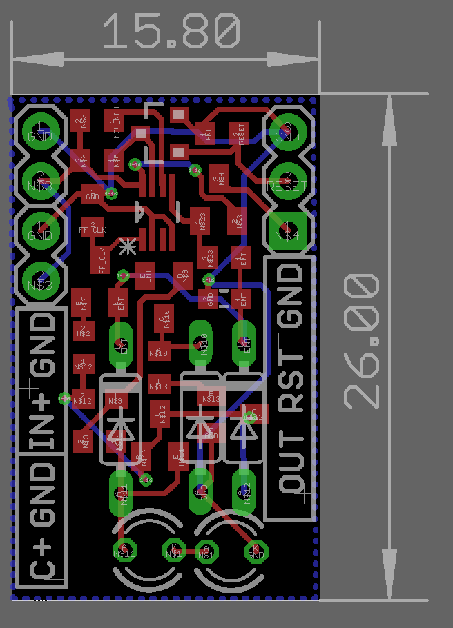
Electron Bucket Power Management PCB
07/15/2018 at 11:47 • 0 commentsThe first version of the PCB for the power management is done.
The PCB has been designed to be small size and compatible with a breadboard making it easy to prototype and incorporate in designs.
![]()
-
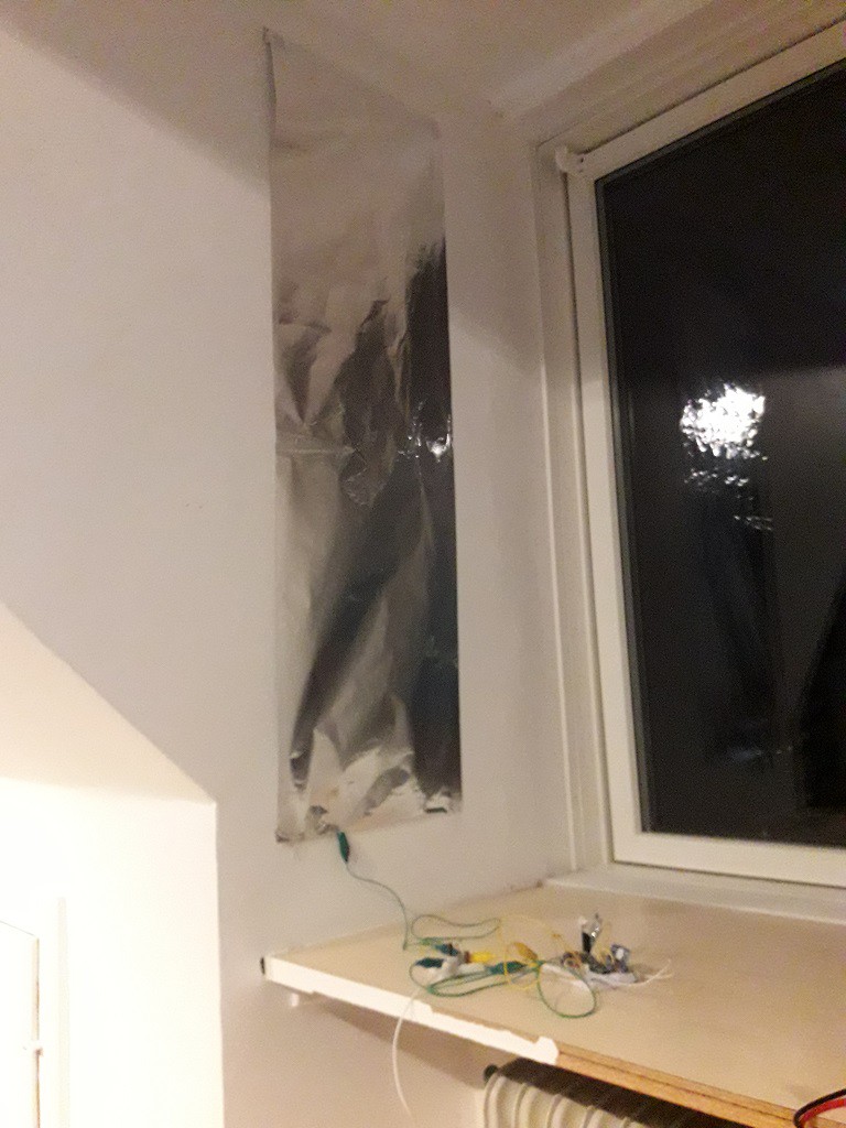
Nearly powering circuit using suspended alu foil
07/15/2018 at 09:07 • 0 commentsOn the pursuit of finding fun and unusual power sources to run the electronics with the help of the power management board I have looked into using the power from the air similarly how a crystal radio works without a power source.
Although I have made a small alternation to the crystal radio concept. Namely, instead of a long antenna and a matching circuit to tune to a station I have used a large piece of aluminum foil.
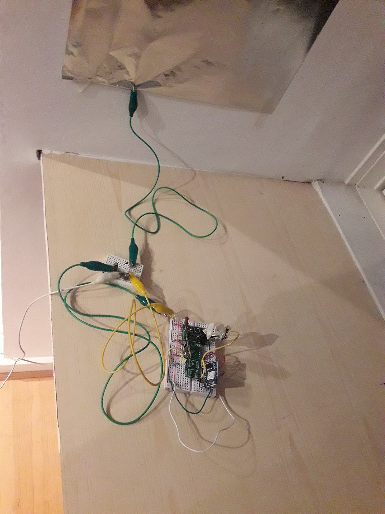
Ultimately the setup was consisting of an aluminium foil connected to one input of a voltage doubler circuit, that acts as a rectifier, and the other input to the voltage double was connected to the central heating system acting as ground. The output of the voltage doubler was connected to the input of the power management. On the output of the power management circuit was a Bluetooth low energy node set to measure the temperature.
This setup was left over night to charge as the amount of current available was expected to be very small. In the morning I have measured 2.6V. This voltage is just at the border of triggering leading me to believe that there just wasn't sufficient current to make the circuit push over the threshold.
Although this didn't work out so far increasing the antenna and maybe tweaking the circuit a bit more would allow powering a system from a very simple power source. Stay Tuned
![]()
![]()
-
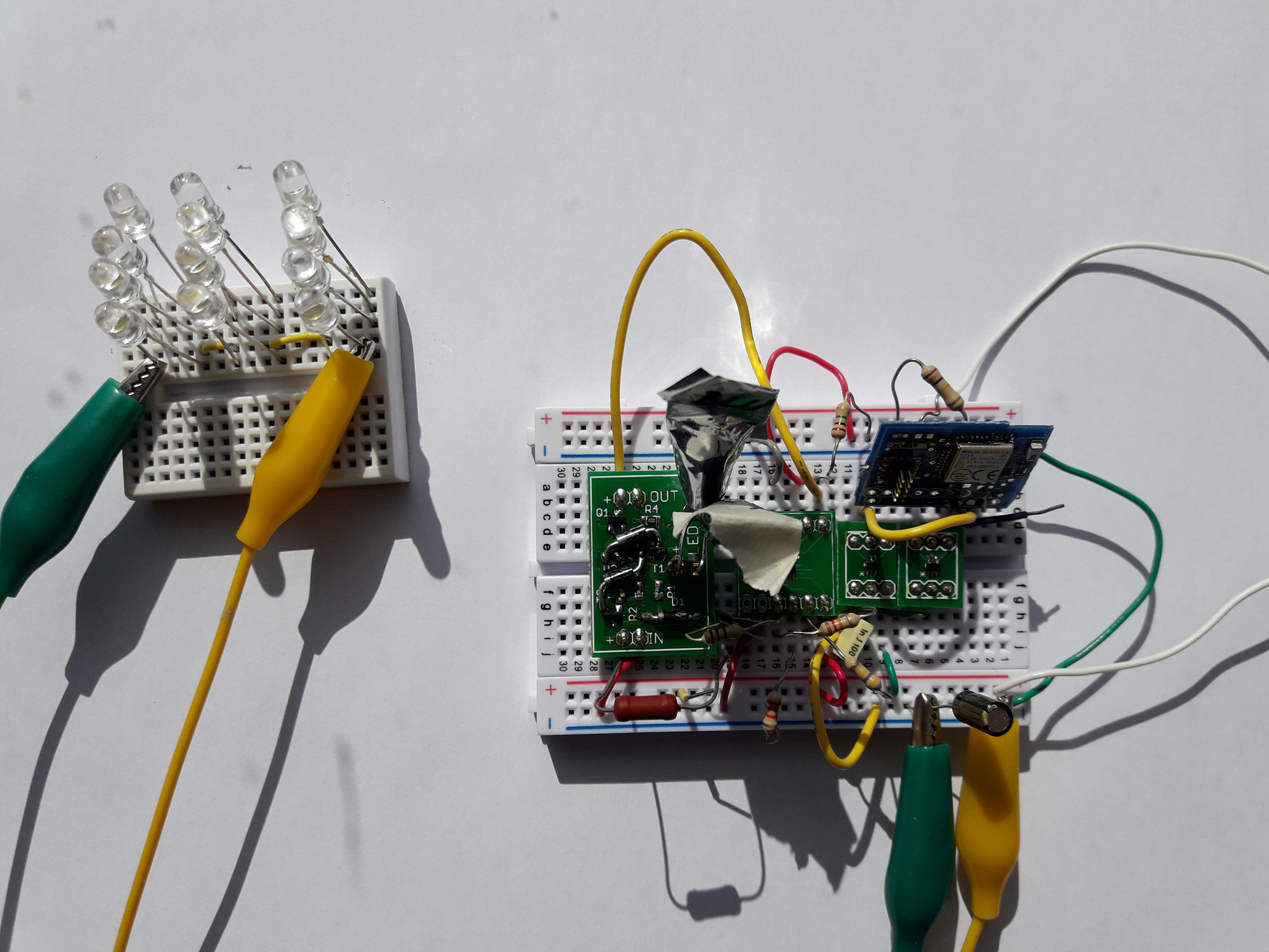
Powering Electronics using LEDs
07/14/2018 at 14:29 • 0 commentsAs the input impedance of the power management circuit is extremely large it is possible to power projects from unusual sources.
In this example I have used a series of LEDs to power a Bluetooth low energy board that transmits temperature measurements. When hit by direct sunlight the LEDs produce about 50nA of current at 0.5V. By combing them in series and parallel it was possible to produce sufficient power to run an application.
With 12LEDs placed in the sun I was receiving wireless packets to my phone every few minutes. With this power management circuit it was possible to turn Light Emitting diodes into solar cells.
![]()
-
Detailed explanation of the circuit
07/14/2018 at 14:14 • 0 commentsIn this log I will take a deeper dive into the operation of the circuit.
The circuit is designed to be stable starting with the buffer capacitor empty. As we attach the power source to the input of the voltage on the buffer capacitor slowly rises on the buffer capacitor. The FlipFlop selected is 74AUP series of digital circuits that have minimal operating voltage of 0.7V but it output starts changing at voltages as low as 0.2V.
As soon as the voltage on the capacitor rises to approximately 0.2V the output Q of the FF matches the supply voltage and starts powering the voltage detector. The circuit continues operation until the activation voltage threshold is reached.
Once the threshold has been reached the output of the voltage detector changes from 0V to VDD. The output of the voltage detector is tied to the CLK input of the FF. The voltage change is interpreted as a rising edge by the FF and the output is changed. As the D output of the FF is tied to ground the Q output goes low thus disabling the Voltage Detector while opening the PMOS that is controlling the power to the load.
Once the load is done performing work it would place a pulse on the reset line of the power management that resets the FF disabling the power to the load and re-enabling the voltage detector. The process repeats itself when the voltage on the capacitor reaches the threshold voltage
Electron Bucket - extreme power management module
When every last nanoamp matters. Powering projects even from LEDs