Close
0%
0%

Precision current generator

A useful tool that injects small currents into your circuits, below the range of your usual lab PSU

Similar projects worth following
As I try to develop bipolar circuits (differential amplifiers, current sense amplifiers, current mirrors...) I need to deal with current below 20mA at decent precision. The low range of a PSU is not very precise so I decided to make my own current generator.
* Simple, cheap, easy
* 20mA down to 5µA
* 2 log pots to fine-tune the current
* powered by a 9V battery (or more)
* floating / isolated operation (not tied to ground or a reference potential)
* output bypass switch
As a bonus, I integrated a small ammeter for direct readout and reduced bench clutter :-)

That's "Yet Another Fork" from #YGREC-ECL:-) (see moving forward

I share this design because it's very handy, cheap, useful and the parameters are easy to adapt for other uses and ranges.

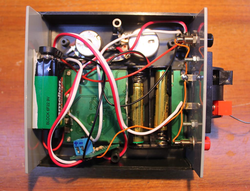
It might look messy but it's just due to poor planning (that's the 2nd prototype)
This generator is based on a classic 2-PNP circuit:
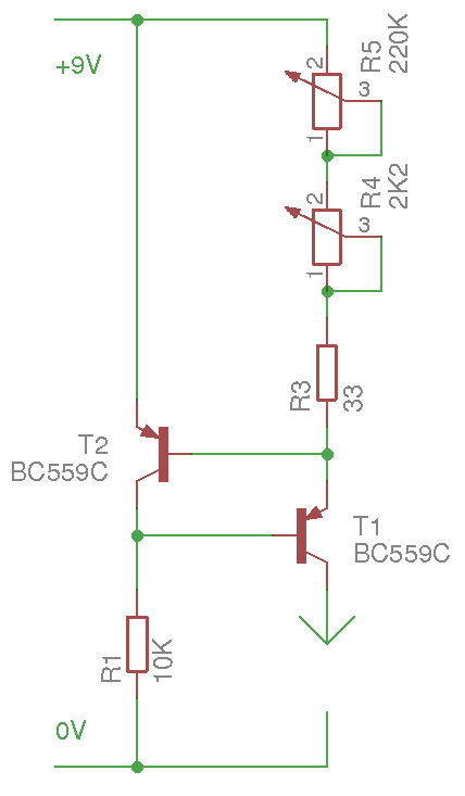
  • R1's value is not critical, it must only be able to supply enough current to turn T1 fully on. The BC559C has a hFE around 500, I want to supply 20mA, so 200µA is more than enough. 10K can provide 1mA (@10V) so it could be increased to almost 50K...
  • T1 and T2 should ideally be identical, from the same lot, to reduce drift (T1 would slightly drift anyway if it conducts some significant current)
  • the current is set by R3+R4+45. T2 keeps their drop below 0.7V so current I=0.7/(R3+R4+R5) (can this be easier to calculate ?)
    For example, when all the pots are down to 0, only R3 remains and it limits the current to 0.7/27=25,9mA (in practice we find 21.6mA because the drop is lower, close to 0.6V)

Conclusion: it's cheap, rather stable and uses very few parts. Another advantage is the low minimal drop: with a 9V battery, the circuit has at least 8V of headroom. Even more headroom is possible if a 2nd battery in series increases the supply voltage to 18V (R1's value would be doubled).


The real circuit is shown below :
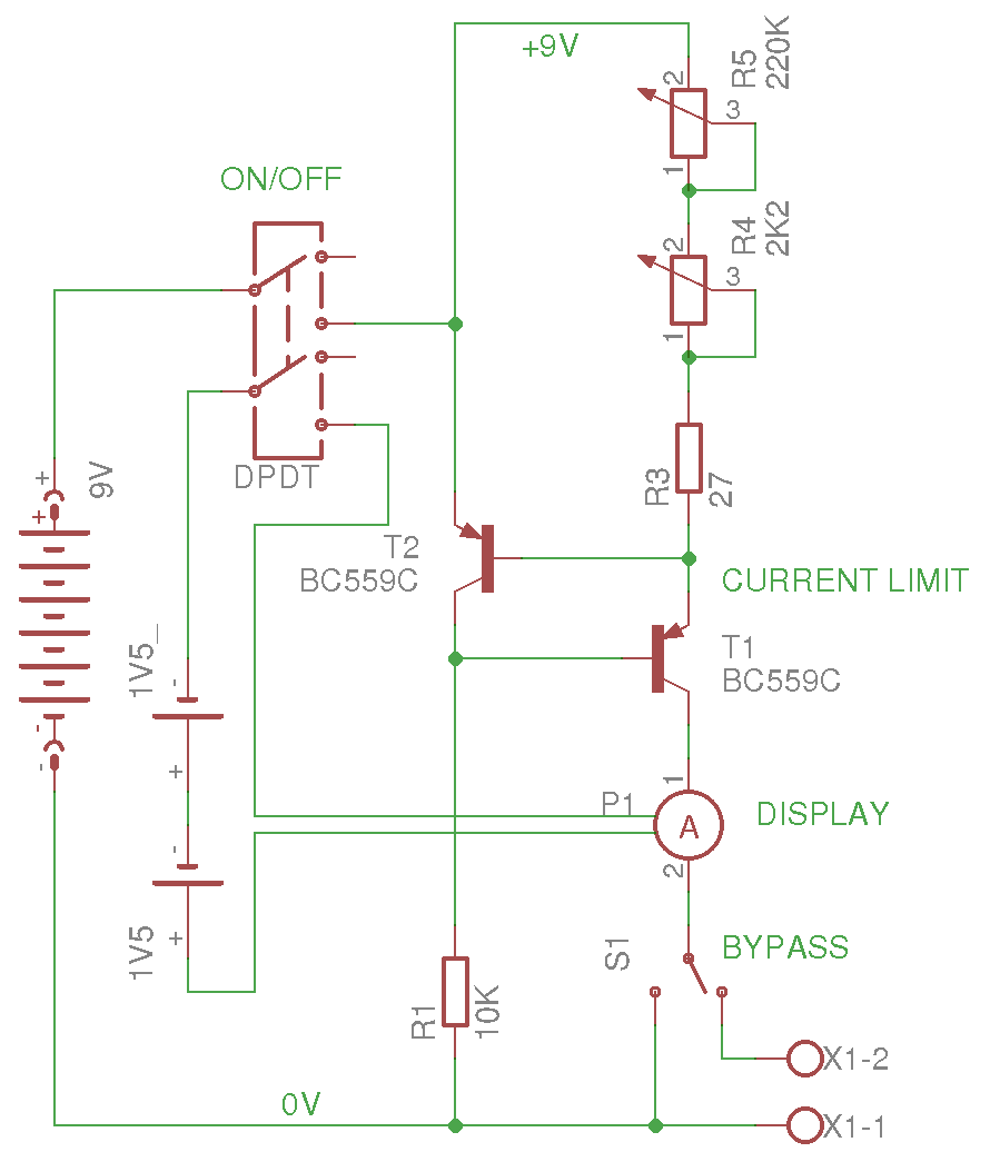
  • A single switch turns the current generator and the ammeter on
  • A bypass switch lets us check the settings without having to short the output with a wire
  • R3 is decreased to 27 Ohms so the max current is about 21mA

Max current (R4=R5=0) : 21.6mA

Min current with only R4 : 0.3mA

Min current with R5 : 4.7µA

The output current is stable from 0V to 8V

The integrated ammeter is only 4000 points and can't show less than 10µA, an additional ammeter in series with the proper range would be required. However, simulation shows that base currents start to become predominant in the µA range so there is no point in going lower...


Logs:
1. Ammeter
2. Bypass
3. Series vs parallel
4. I've been HADed again !
5. Simulation with falstad
.

  • Simulation with falstad

    Yann Guidon / YGDES07/18/2018 at 17:54 0 comments

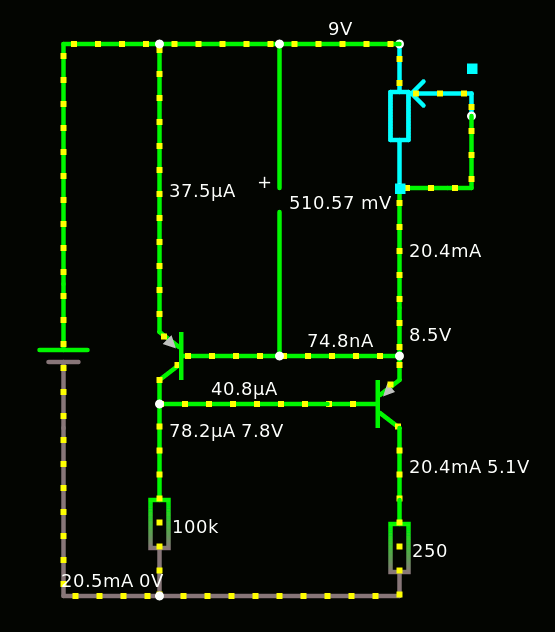
    Jim made a simulation on the online interactive simulator falstad, available there : http://tinyurl.com/ycj63egd

    I've tweaked it a little (I display more values) :

    $ 1 0.000005 7.619785657297057 65 5 50
    t 224 240 176 240 0 -1 0.6771607865907852 -0.5873050244463638 500
    t 256 272 304 272 0 -1 1.8738439949380101 -0.6771607865907852 500
    r 176 304 176 400 0 10000
    v 80 288 80 192 0 0 40 9 0 0 0.5
    w 176 304 176 272 3
    w 176 272 176 256 0
    w 176 224 176 32 1
    w 176 32 80 32 0
    w 80 32 80 192 0
    w 80 288 80 400 0
    w 80 400 176 400 3
    w 176 400 304 400 0
    w 304 336 304 288 3
    w 304 240 224 240 1
    174 304 128 352 48 0 5000 0.9950000000000001 Resistance
    w 176 32 304 32 2
    w 304 256 304 240 0
    w 304 240 304 208 2
    w 304 128 336 128 0
    w 352 80 352 128 0
    w 352 128 336 128 0
    w 256 272 176 272 1
    w 304 128 304 208 1
    r 304 336 304 400 0 250
    

    The simulation is really useful and interesting:

    For example the current through the 10K resistor varies very little, hence the voltage across it. That means that it could be increased easily.

    The base current of the feedback transistor is very small, which explains the 0.6V across the potentiometer. This current is still above the range of the generator (220K limits to 5µA) but it could limit this value or affect the linearity of the circuit.

    The base current of the pass transistor can be even lower !

    The base voltage of the feedback transistor is almost fixed to 0,589V, it's pretty amazing (almost like a constant voltage generator, it's good to know !)

    Thanks again @Jim!


    Some tweaks show that the fixed resistor R1 can be increased to 100K in my case, with a bit of headroom. It's too late now but this would reduce the quiescent current...

    However the feedback transistor is starved and its Vbe drops to 510mV...

  • I've been HADed again !

    Yann Guidon / YGDES07/18/2018 at 09:58 4 comments

    https://hackaday.com/2018/07/18/how-low-can-you-go-tiny-current-generator/

    I'm glad this "quick and dirty project" received some attention, and I hope it helps others !

  • Series vs parallel

    Yann Guidon / YGDES07/13/2018 at 03:39 0 comments

    The tuning pots are logarithmic, with values of 2K2 and 220K.

    They are wired in series : when used for very low currents, the 220K does the coarse value and it can be refined by the 2K2 pot.

    But not the reverse...

    A "range" switch should be added to connect the pots in series or parallel. The parallel mode would use the 220K for fine-tuning the coarse high current pot, above 1mA.

    I'll do this when I can, but the box is already pretty crowded and I don't want to add dust...

  • Bypass

    Yann Guidon / YGDES07/13/2018 at 00:26 0 comments

    I added a bypass switch.

    It disconnects the outputs and shorts the generator to 0V, so you can check that everything works well (for example, if some saturation is suspected). You don't need to short the output with a wire to set the max current :-)
    Because this is how it looked before :

    ... less elegant, right ?

  • Ammeter

    Yann Guidon / YGDES07/13/2018 at 00:03 0 comments

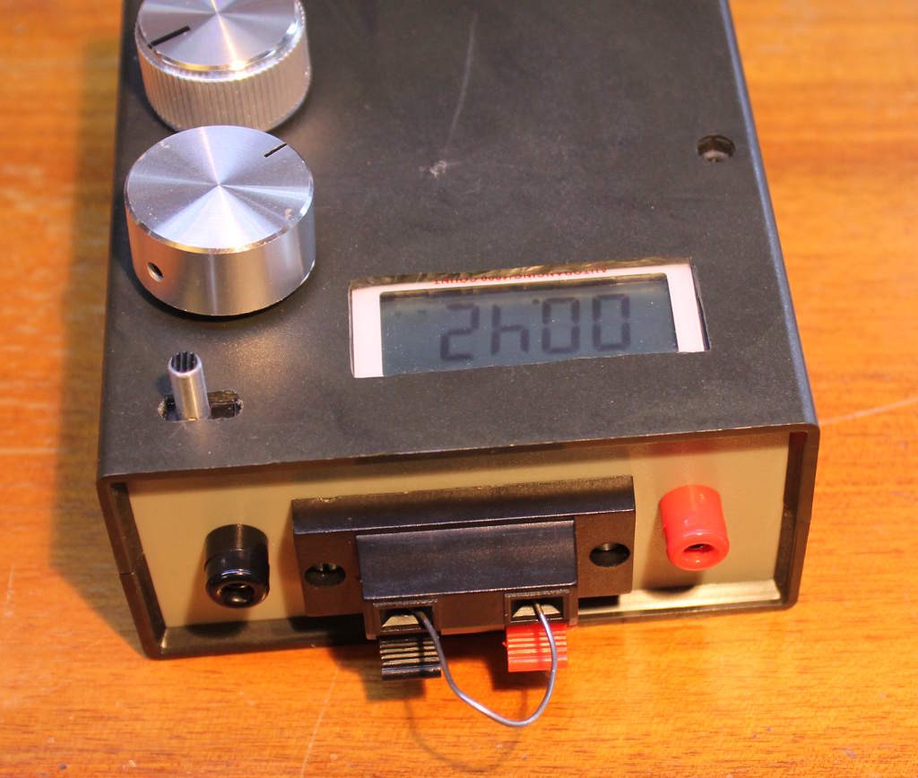
    For the current display, I have hacked a  JT-033A :

    It's a decade-old device that was laying unused in my multimeters bin, because its probes were damaged.

    The autorange does not work in the very low currents :-( but it's sufficient for the 20mA-0.1mA range.

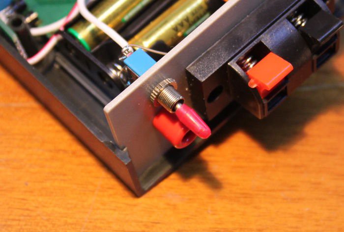
    It's powered from two alkaline coin cells, at 3V. I replaced them with a battery holder for AAA batteries.

    The rotary selector is removed and the contacts are shorted by solder bridges.

    I'm glad I didn't damage the LCD screen :-D

View all 5 project logs

Enjoy this project?

Share

Discussions

ogdento wrote 07/20/2018 at 16:20 point

nice work... where did you get that project box?

  Are you sure? yes | no

PinheadBE wrote 07/18/2018 at 17:41 point

Why BC559C ?  Just because you had them in your drawer, or because they have a special characteristic that makes them a better choice than another common PNP ?

  Are you sure? yes | no

Yann Guidon / YGDES wrote 07/18/2018 at 17:58 point

let's just say I bought a few bags of them 2 years ago, for a transistor computer project :-)

They have nice characteristics (hFE in the 500 ballpark, and a lot of Vce headroom) so I could match a pair.

Most self-respecting PNP pair could work, of course.

  Are you sure? yes | no

Jim wrote 07/18/2018 at 13:42 point

I've always had a hard time getting my head around these kinds of circuits, so I mocked it up in Falstad's circuit simulator: http://tinyurl.com/ycj63egd

Maybe others will find this useful.

I had to make a couple of changes. The simulator doesn't allow potentiometers to go to either extreme, so I had to make the pot 5k. This makes its minimum 25 ohms, which also allowed me to get rid of the 33 ohm resistor. I also put in a load.

One can easily add voltage or current meters by just right-clicking on components.

  Are you sure? yes | no

Yann Guidon / YGDES wrote 07/18/2018 at 16:18 point

Thank you very much Jim !

I'll see if I can make a video :-)

  Are you sure? yes | no

Yann Guidon / YGDES wrote 07/18/2018 at 17:40 point

I made a short video there : https://youtu.be/AsSRFWnn9dA

I'll add a log as well :-)

  Are you sure? yes | no

Jim wrote 07/18/2018 at 18:37 point

Nice! I'm a big fan of those Falstad tools, especially the circuit simulator.

  Are you sure? yes | no

Similar Projects

Does this project spark your interest?

Become a member to follow this project and never miss any updates