-
Simulation with falstad
07/18/2018 at 17:54 • 0 commentsJim made a simulation on the online interactive simulator falstad, available there : http://tinyurl.com/ycj63egd
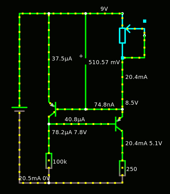
I've tweaked it a little (I display more values) :
$ 1 0.000005 7.619785657297057 65 5 50
t 224 240 176 240 0 -1 0.6771607865907852 -0.5873050244463638 500
t 256 272 304 272 0 -1 1.8738439949380101 -0.6771607865907852 500
r 176 304 176 400 0 10000
v 80 288 80 192 0 0 40 9 0 0 0.5
w 176 304 176 272 3
w 176 272 176 256 0
w 176 224 176 32 1
w 176 32 80 32 0
w 80 32 80 192 0
w 80 288 80 400 0
w 80 400 176 400 3
w 176 400 304 400 0
w 304 336 304 288 3
w 304 240 224 240 1
174 304 128 352 48 0 5000 0.9950000000000001 Resistance
w 176 32 304 32 2
w 304 256 304 240 0
w 304 240 304 208 2
w 304 128 336 128 0
w 352 80 352 128 0
w 352 128 336 128 0
w 256 272 176 272 1
w 304 128 304 208 1
r 304 336 304 400 0 250
The simulation is really useful and interesting:
For example the current through the 10K resistor varies very little, hence the voltage across it. That means that it could be increased easily.
The base current of the feedback transistor is very small, which explains the 0.6V across the potentiometer. This current is still above the range of the generator (220K limits to 5µA) but it could limit this value or affect the linearity of the circuit.
The base current of the pass transistor can be even lower !
The base voltage of the feedback transistor is almost fixed to 0,589V, it's pretty amazing (almost like a constant voltage generator, it's good to know !)
Thanks again @Jim!
Some tweaks show that the fixed resistor R1 can be increased to 100K in my case, with a bit of headroom. It's too late now but this would reduce the quiescent current...
![]()
However the feedback transistor is starved and its Vbe drops to 510mV...
-
I've been HADed again !
07/18/2018 at 09:58 • 4 commentshttps://hackaday.com/2018/07/18/how-low-can-you-go-tiny-current-generator/I'm glad this "quick and dirty project" received some attention, and I hope it helps others !
-
Series vs parallel
07/13/2018 at 03:39 • 0 commentsThe tuning pots are logarithmic, with values of 2K2 and 220K.
They are wired in series : when used for very low currents, the 220K does the coarse value and it can be refined by the 2K2 pot.
But not the reverse...
A "range" switch should be added to connect the pots in series or parallel. The parallel mode would use the 220K for fine-tuning the coarse high current pot, above 1mA.
I'll do this when I can, but the box is already pretty crowded and I don't want to add dust...
-
Bypass
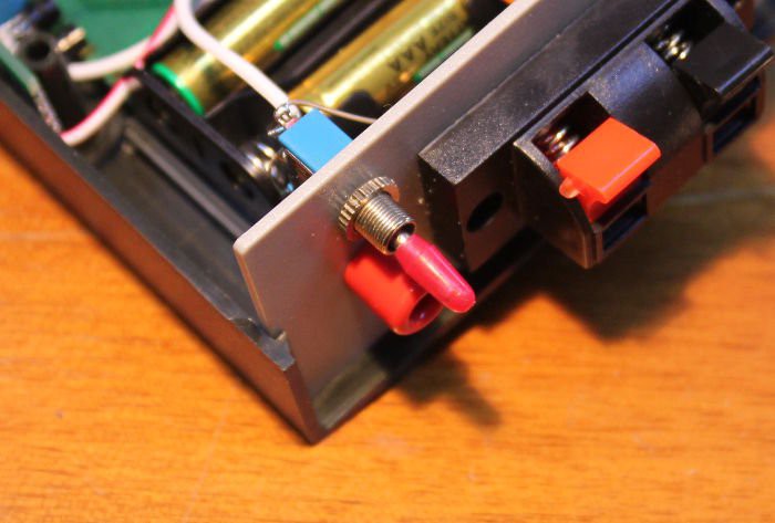
07/13/2018 at 00:26 • 0 commentsI added a bypass switch.
It disconnects the outputs and shorts the generator to 0V, so you can check that everything works well (for example, if some saturation is suspected). You don't need to short the output with a wire to set the max current :-)
Because this is how it looked before :... less elegant, right ?
-
Ammeter
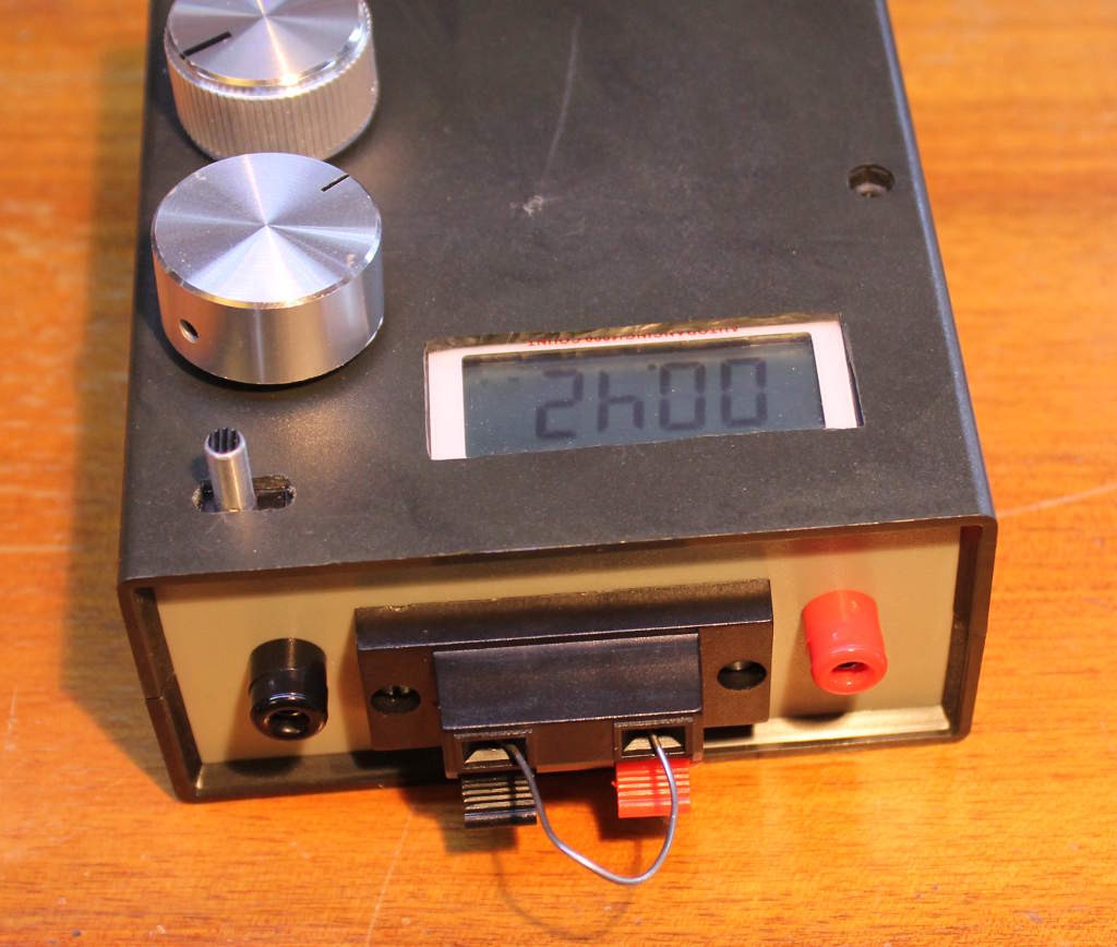
07/13/2018 at 00:03 • 0 commentsFor the current display, I have hacked a JT-033A :
![]()
It's a decade-old device that was laying unused in my multimeters bin, because its probes were damaged.
The autorange does not work in the very low currents :-( but it's sufficient for the 20mA-0.1mA range.
It's powered from two alkaline coin cells, at 3V. I replaced them with a battery holder for AAA batteries.
The rotary selector is removed and the contacts are shorted by solder bridges.
I'm glad I didn't damage the LCD screen :-D
Precision current generator
A useful tool that injects small currents into your circuits, below the range of your usual lab PSU
 Yann Guidon / YGDES


