 J3TTBlack88
-
1Step 1
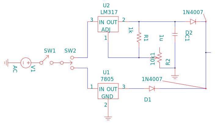
The LM317 output voltage (between a minimum of 1.25V and maximum of 44V) is determined by the resistors (R1 and R2) in the Oregano circuit diagram, with the equation below.
NOTE: Remember to include your diode voltage in your calulations.
NOTE2: Fine and coarse voltage control could theoretically be achieved with a 1k and a 5k linear potentiometer.
-
2Step 2
Arrange the components, according to the circuit diagram, on the protoboard to be used and solder it up.
![]()
-
3Step 3
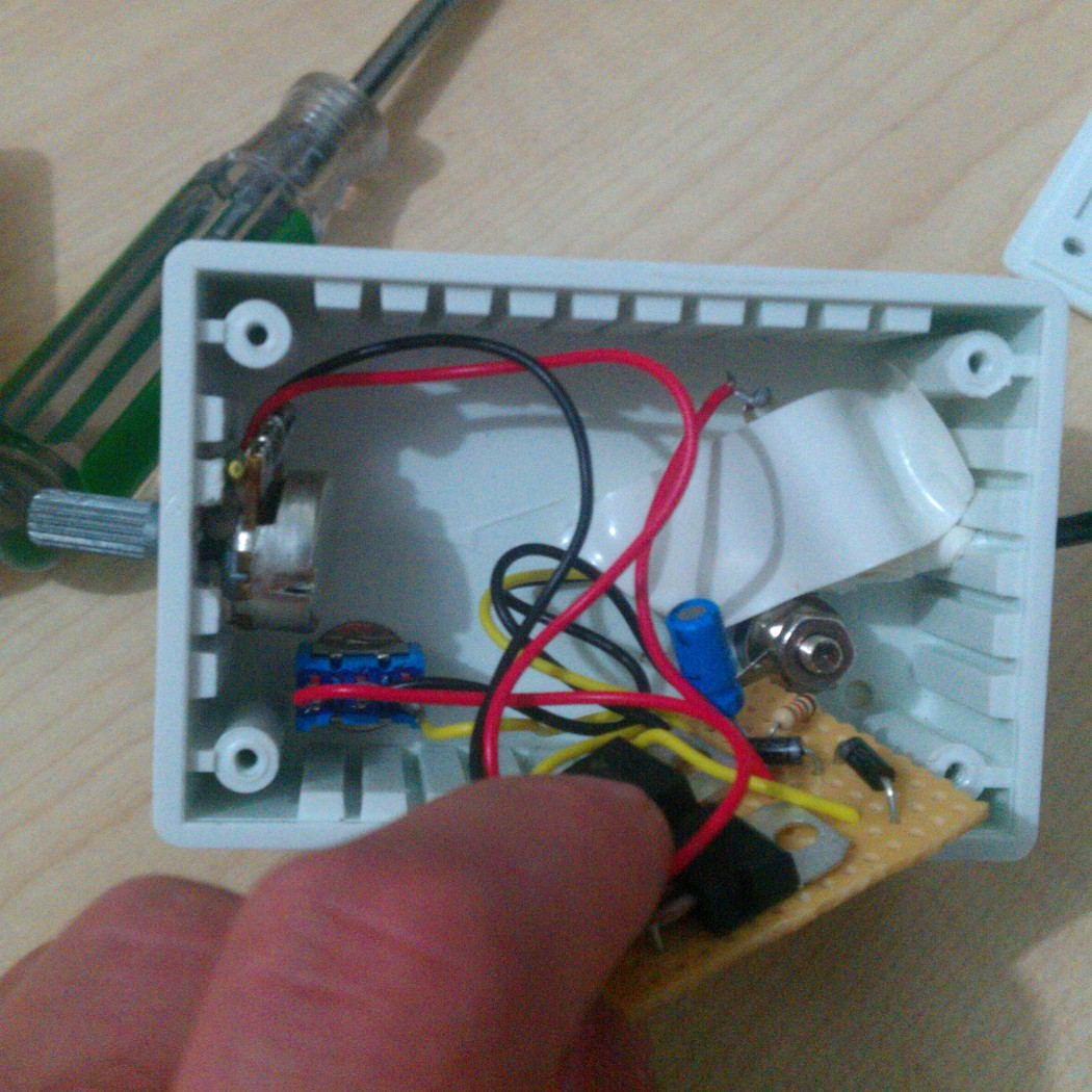
You will now need to prepare your housing. I had duffed a previous project so had this housing available but a Dremmel makes light work of it but the exact arrangement depends on your components, I was fortunate enough to have quite a small 10k potentiometer.
-
4Step 4
The next step is to pplace all your components. I used my toggle switch pointing at my potentiometer for variable output but this is obviously a personal choice. The banana plugs I used also just screwed into place and I passed my power lead through the back of the device.
-
5Step 5
Now soldering the switch, banana plugs, potentiometer and power lead into the protoboard, close your enclosure. I covered the terminals of my banana plugs with PVC tape for piece of mind (I also happen to have lost my potentiometer's nut so I'm using prestik :-/).
![]()
![]()
-
6Step 6
Despite my stale comments, this build was quite straight forward (that much I remember quite clearly) once I had all my components. I later added an isolating lamp switch to the power lead but besides that, you can just close the enclosure and you're good to go. I can't suggest making banana leads for your volt meter enough (or buying them), it makes everything simpler.
Low cost var. out PSU with laptop adapter
A common ground PSU with 2 to 17V variable or 5V linear output using a laptop power adapter and an external multimeter

Discussions
Become a Hackaday.io Member
Create an account to leave a comment. Already have an account? Log In.