Close
0%
0%

Pulse sensor to actuate a Robotic Hand

We are trying to implement a pulse sensor to actuate a 3D printed prosthesis instead of the myoelectric ones. That's a first, we think.

Public Chat
Similar projects worth following
For the last 2 years we have been making a robotic prosthetic hand and everybody thinks its cool and all, but the same question always comes up. How is someone going to control it. We used the MyoWare Muscle Sensor for a long time and it works great, however when we started trials with Andres (he's going to come up a lot) we noticed that the way that the sensor attachs (from 3 points!) wasnt goin to work. So as our last succesfull project (https://hackaday.io/project/156520-3d-printed-mini-linear-actuator) we decided to make our own!

We used to work with the myoWare sensor(https://www.adafruit.com/product/2699) and dont get us wrong, it works great and much better that our implementation in many ways. 

But the main goal now it's ease of use, including the setup process. That in the myoWare involves sticking 3 electrodes.

So the video will give you a better idea :

We will introduce Andres fomrally in due time but the reason for grabbing a pulse sensor(https://www.adafruit.com/product/1093) and making it a muscle contraction detector its that it is really easy to put on and down. 

Basesensor1.stl

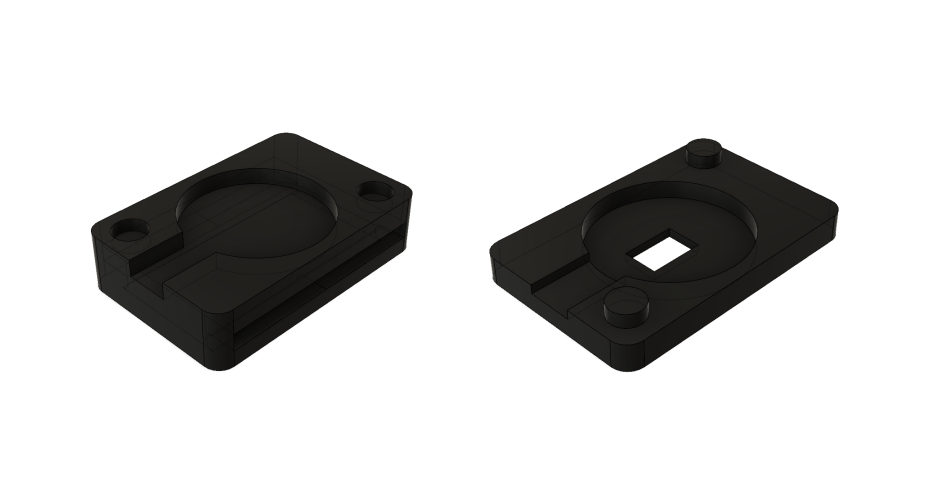
Case of sensor

Standard Tesselated Geometry - 58.77 kB - 08/01/2018 at 16:51

Download

Tapasensor.stl

Case of sensor

Standard Tesselated Geometry - 43.73 kB - 08/01/2018 at 16:50

Download

Socket.stl

Standard Tesselated Geometry - 473.81 kB - 08/01/2018 at 15:35

Download

Myoware.stl

Ready to print cover of the MyoWare Muscle Sensor

Standard Tesselated Geometry - 44.42 kB - 07/30/2018 at 20:32

Download

Final_solo_pinza2.ino

the whole code for the hand... including the sensor part

ino - 8.11 kB - 07/30/2018 at 20:32

Download

View all 7 files

  • The Flexible union

    Jonathan Díaz08/22/2018 at 21:58 0 comments

    Between the socket and the arm is the flexible union, we have made it a flexible ninjaflex filament. This part is very important since it ensures the fit between the arm and the socket.

    In order to make the model we had to make several tests, the flexible union must have the measurements of the stump for the precise adjustment but achieving this can be a real headache if we do not use the right tools.

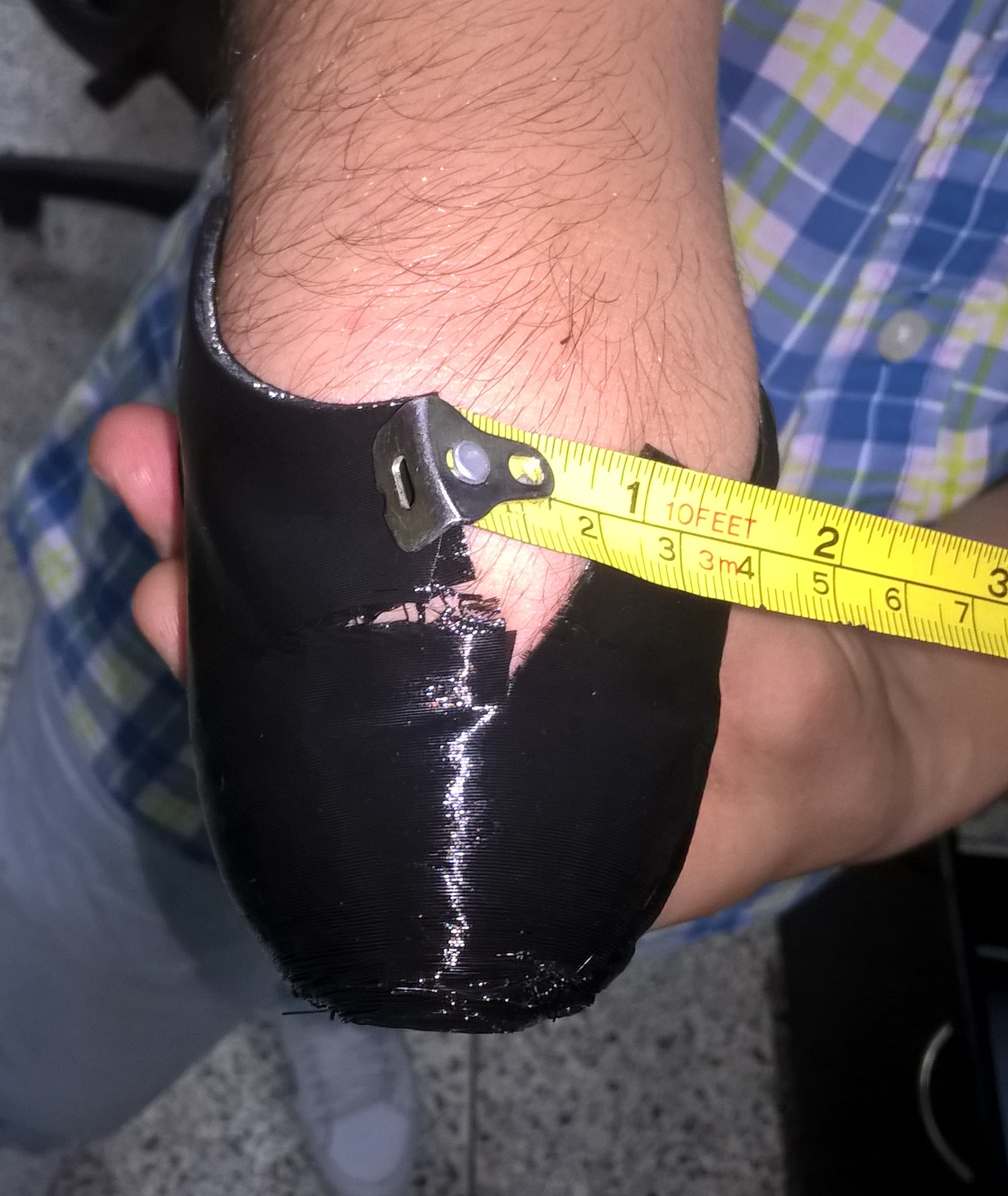
    At first we tried with eye and tape measure what did not give us good results (obviously), As seen in the images, sometimes the union was very small and sometimes very large.

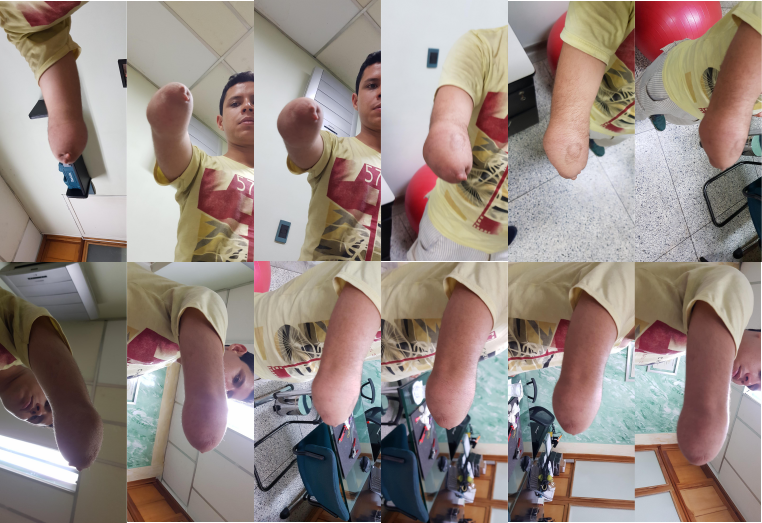
    There are 3d scanners, but at that time we had no possibility of obtaining any, which made us try with 3d photogrammetry, It was a new method for us but we tried it with some dedicated programs for that purpose.

    At the end we choosed by Autodesk Recap, although in its free version every time we want to generate a model we must wait in line until there is space on the server, in our case it was something like 24 hours.

    The images that we created to generate the 3D model were something like this:

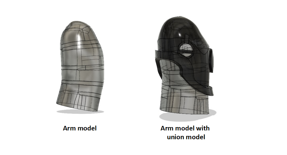
    And the result was something like that: 

    After the model was imported to fusion 360, with this it was possible to generate the model of the union with greater precision

  • Walking with the arm

    Giovanni Leal08/14/2018 at 16:48 0 comments


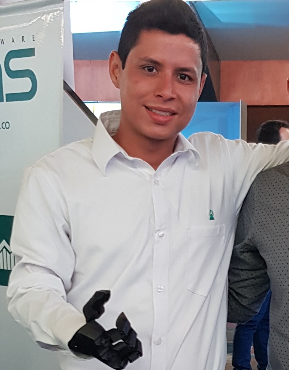
    So the ultimate test of the project has been that Andres took the arm with him 2 months ago. Having something that we made with our hands on the wild is an incredible feeling.

    However we have been on our toes keeping an eye for any suggestion that he would make and incredibly he only had one complain!

    The thing was that when he was walking the hand tend to open and close. Obviously this was unconfortable to him because people tend to look when they hear the grind. So why is this happening?

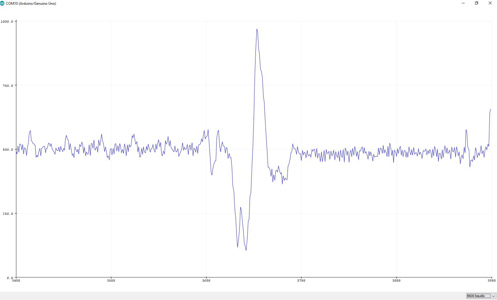
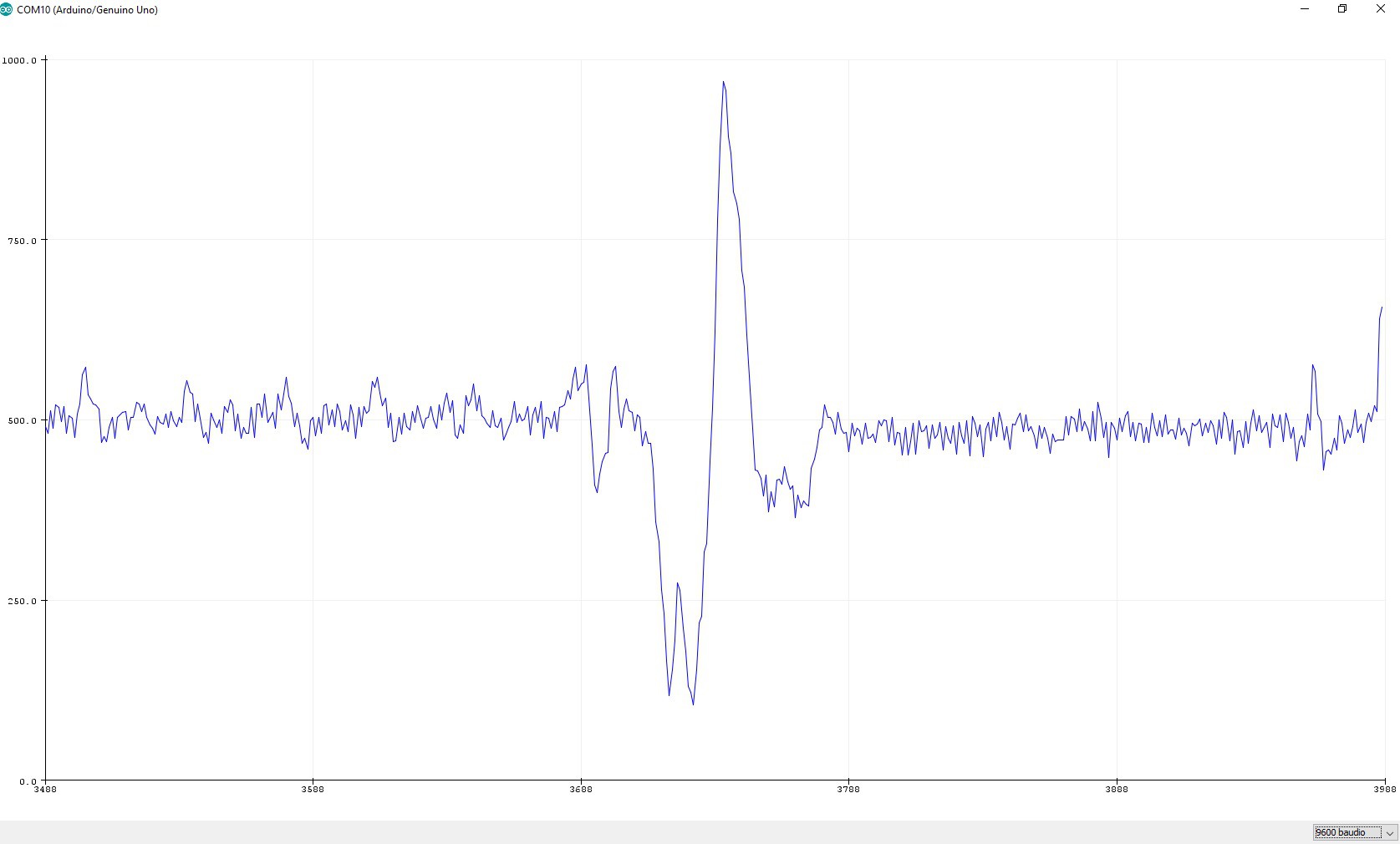
    As you see on the next graph, the input we get its very "spiky" when someone walks.

    So one of us was watching a video from James Bruton, by the way great projects hope to see that rocket being more than a missile, and we saw that he applied a simple formule to smooth those spikes.  (he also took it from somenone else as he explains)

    So the equations is something like this:

    The filter variable is a factor that you should tweak to get that nice curve that will get your input usable.

    If you watch the last part of this video(2:05) that we published, we show the arm and Andres drops the cap, he moves around and the hand stays closed!

    Thats a huge win for us and we hope that it works for you has you saw in James video it has endless applications.

  • The Hand

    Jonathan Díaz08/10/2018 at 20:20 0 comments

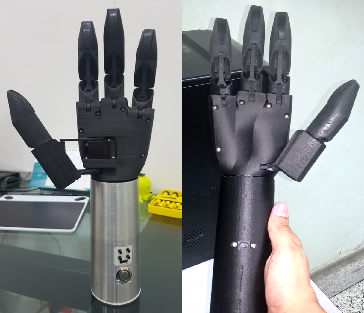
    So a lot of you have been asking about THE HAND.

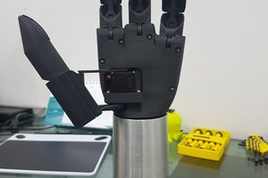
    The hand is taken from a project that was presented in 2016, this project is available in https://hackaday.io/project/13339-tns-1i, modifications were made to the design, such as the servomotor at the base of the thumb that is now inside the hand and a bunch of the internals that if you are really curious youll pick it rigth up. 


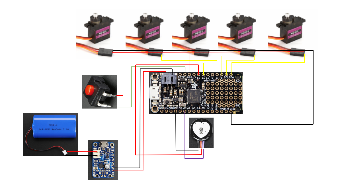
    Also the base of the engines have been improved, but if you want to build the hand, reviewing that project you can achieve it. Carbon fiber PLA from proto pasta is used to print the parts and a 0.4 mm nozzle. The conections are explain in the instructions section, but with the next image you can guide. This achieves the goal that the whole contraption weights less that 400 grams, with batteries.

    We hope you can make a great hand!

  • The sensor part

    Giovanni Leal07/31/2018 at 17:06 0 comments

    So, to the nitty gritty.

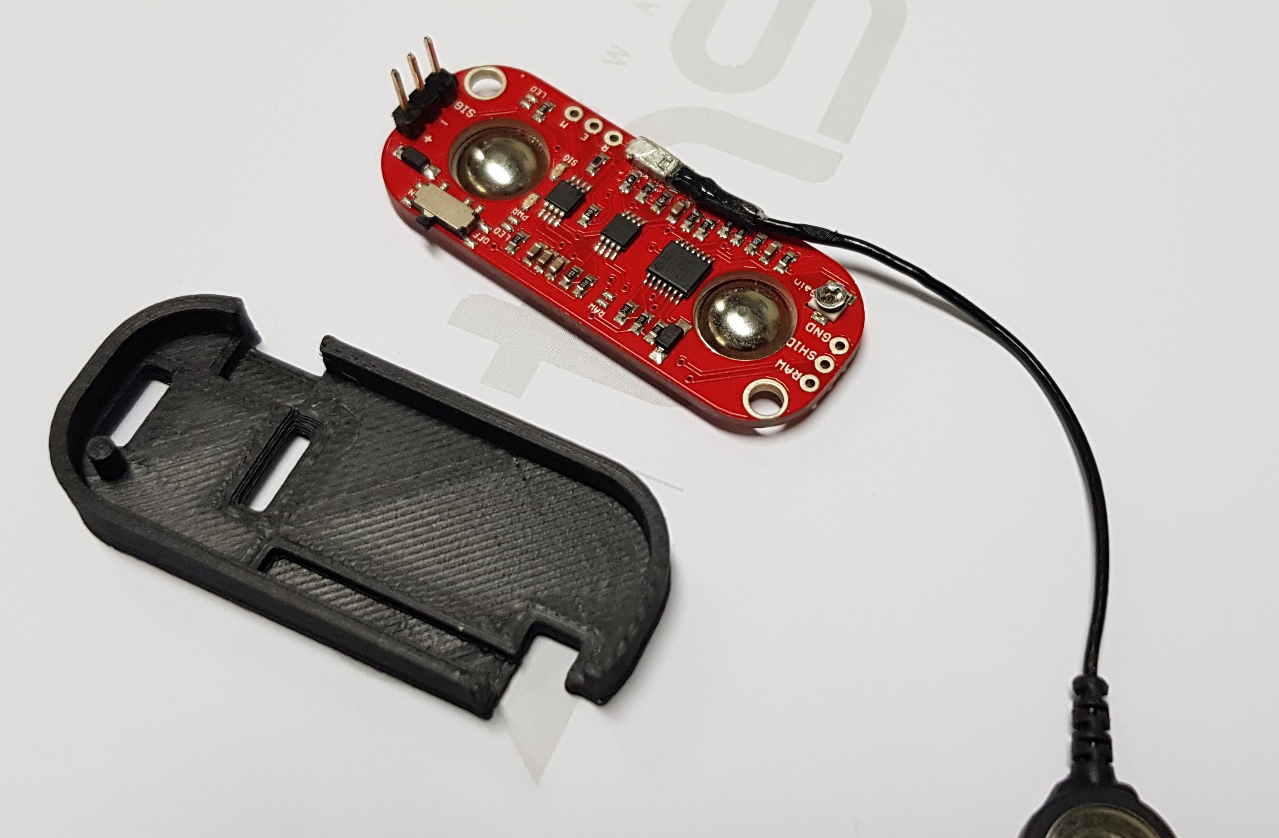
    Before everything, we want to be clear, the Myoware sensor it's great really we used to actuate the hands with it. We even made a cover for it!!!! look!

    If you want to use it go ahead it is on the files section, the .stl and the original file are there if you want to upgrade it.

    The problem with the sensor is one, it is not practical. It's much better than the last version with the double A batteries but still the process of put in on with the electrodes and the fact that we couldnt find locally other electrodes that worked made it really hard to work with. 

    One day i was trying to get my pulse with my Samsung gear S3 and i noticed that when i moved my wirst it picked up.... so we buyed 2 pulse sensors put it on a part that doesnt have a lot of veins or arteries and it works! The part of the vascularity its very important else it will pick your pulse.

    The code for the whole project its up there. If you want to modify the sensitivity just play with this conditional on the code.

    if (sensorfiltrado < 500) {
    

    If you see on the graphic the signal goes down first so thats why the conditional pick up a lesser value than.....

     Clearly this one has a lot of noise but that's the subject for another post. So as always feel free to ask us anything, it would be great on the comments not private.
  • Let's talk sockets

    Giovanni Leal07/26/2018 at 20:26 0 comments

    So, history time.

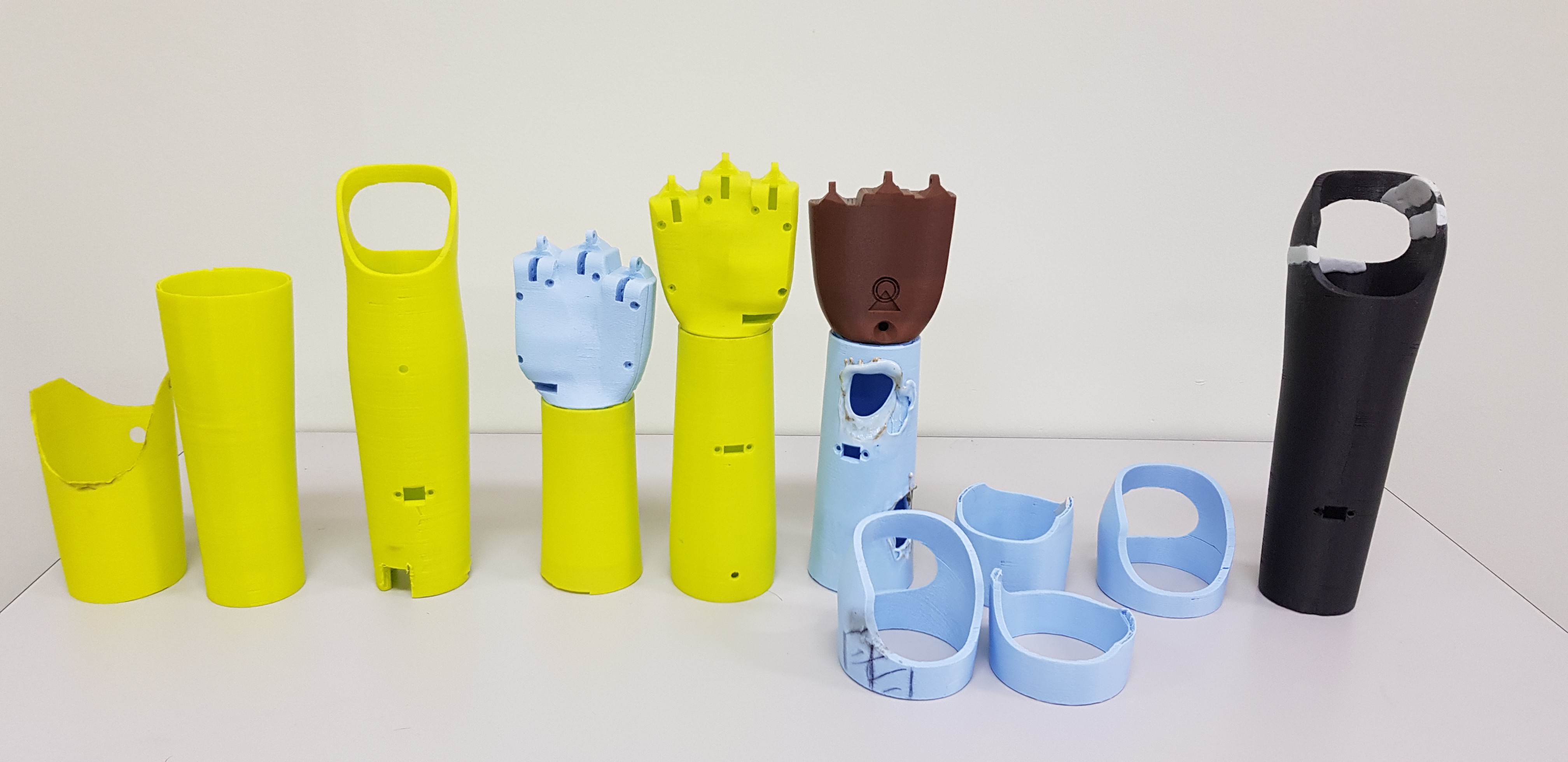
    When we "finished" the hand and  were ready to give it to Andres to wear it we had the problem about what goes between the hand and the sensor. We went to some local prostethic sensor like we'll buy it give them some directions for holes for the charging port and that's it. What we didn't know was that each socket cost well upwards $1000 USD!!!

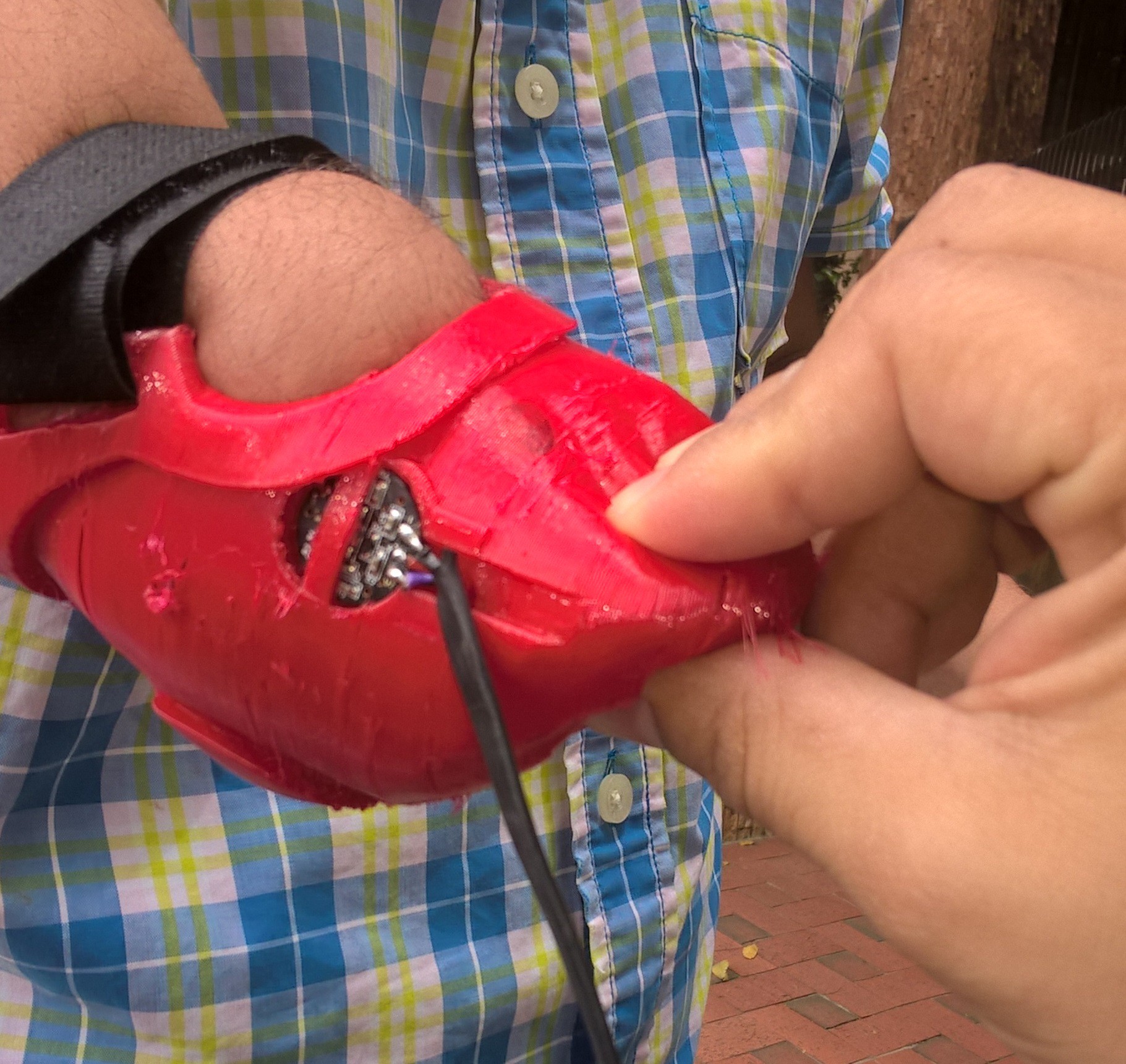
    Sooo that eliminates tha chance of trying it more that once. For example, at the begining we used a panel mount extension for the usb conection(https://www.adafruit.com/product/3258) at the socket and we needed to implement those powerboost(https://www.adafruit.com/product/2465), let me tell you those boards are life savers, so with the powerboost we didnt need the bolts outside but if we had spend $1000 bucks we would have holes outside just because..... the other 10 times that we change it it beacuse it keep breaking :

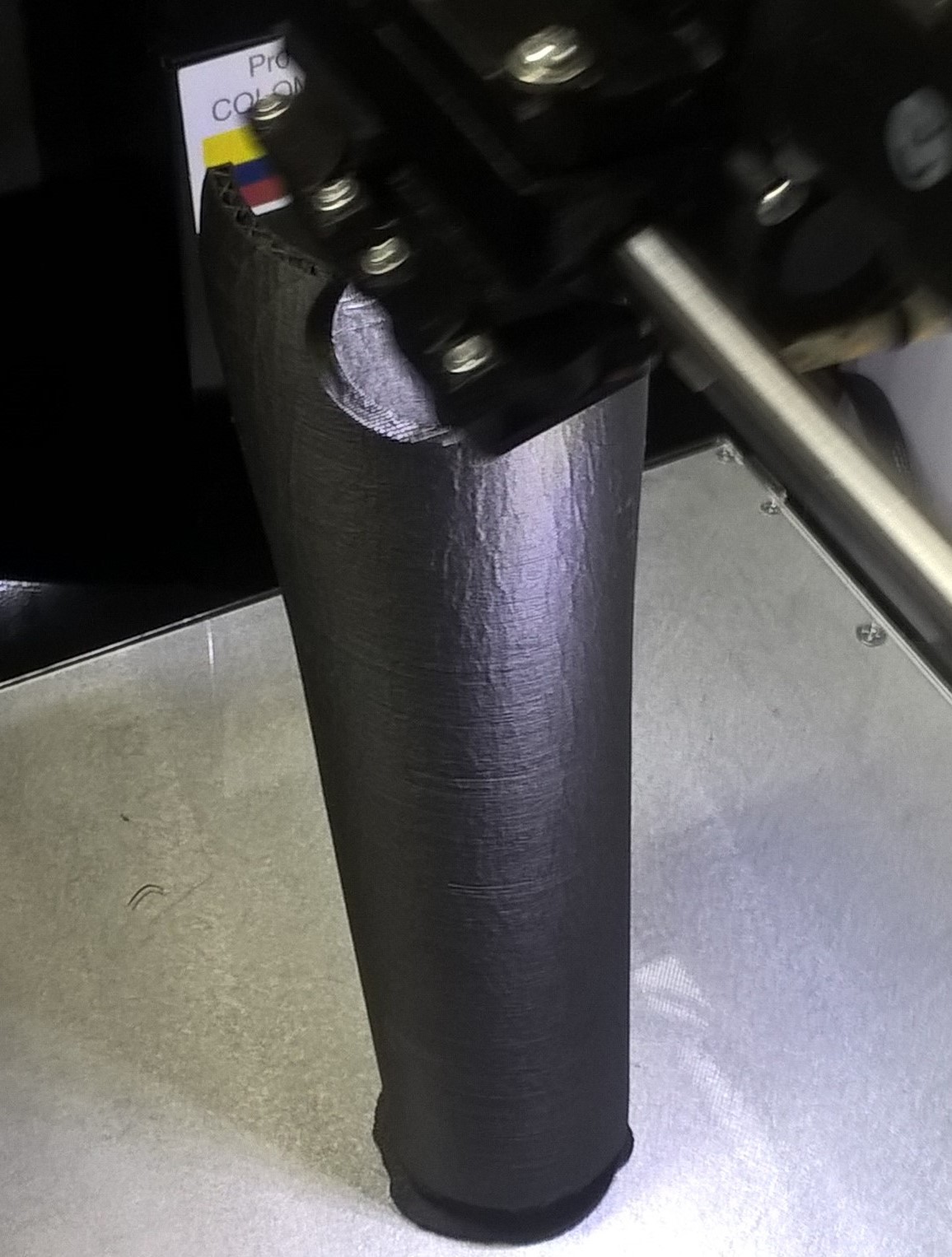
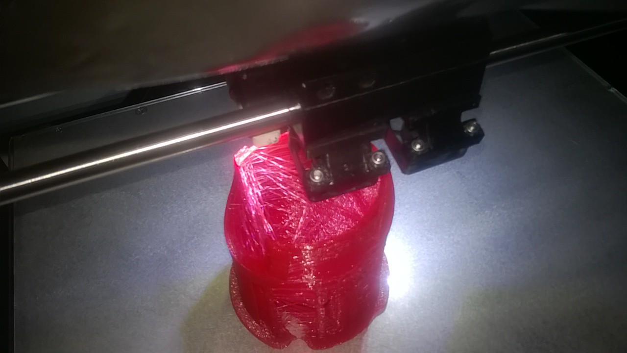
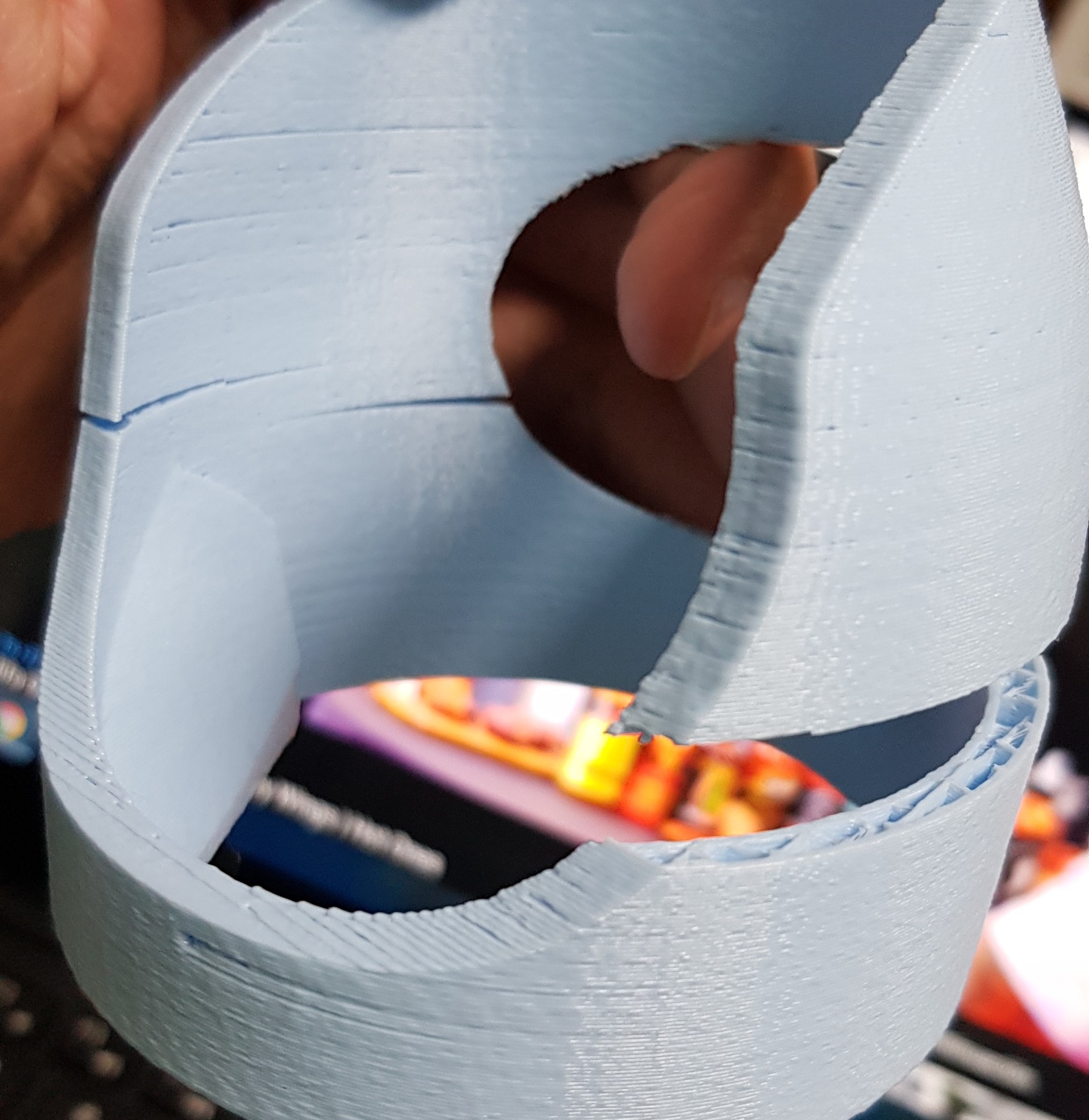
    So about the breakings on the close up you'll see the problem.... the printlines, but it's obvious that you are going to print this thing uprigth. Its 7 hours that way, sideway would be more than double and with imperfections. 

    Close Up:

    So we tried many things.... and it ketp breaking.... we put bondo on it for him to use it until we figure it out!!! We passed the soldering iron on the sides..... we know... crude but that things looks and holds like ceramic. Really like those guys at proto pasta should look into it. 

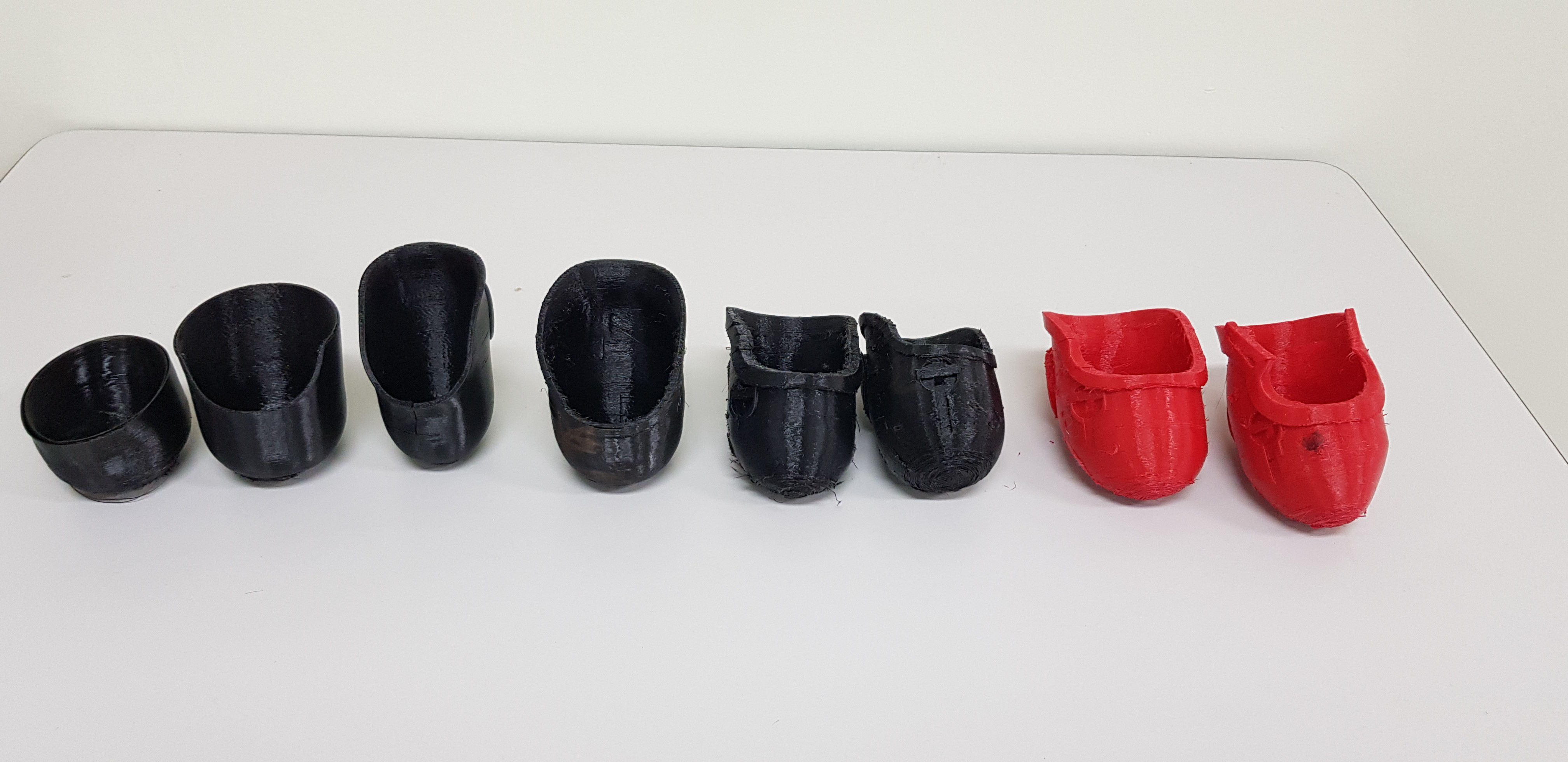
    For the flexible part the thing was figuring out the postion for the sensor:

    At the end we place the sensor outside but thats another log....

    Conclusion, we did it... really was a dificult task but it works great.... holds the battery inside.... custom made.... ceramic like.... comfortable(acording to Andres)... we are really really happy because we did something ourselves, much better, all the process for half the price and we learned. So if you hace any question ask it down there. 

    A lot of peolpe asked what Andres does for a living, he is a accountant on an eviromental branch of the goverment.

  • Meet Andres

    Giovanni Leal07/23/2018 at 21:36 0 comments

    Hi everyone. So this post isnt about tech or hacking.

    This is a way from the team to say thank you to Andres. You see, the project that we have been working on couldnt be in this stage if we havent meet him. So on the next post we will show you our many tries to implement a different kind of sensor and to create a 3d printed socket that fits and looks nice.

    So.... thank you for your time and patience man, we really apreciate it.

View all 6 project logs

  • 1
    Checking to start

    First check the you have necessary materials to make the project. You need some 3D printed parts, so a printer is necessary or at least the posibility of print. We print with protopasta carbon fiber filament but you can print in PLA, thats if you want to strap the sensor to your arm. If you want to embed the sensor to a socket we recommend to use a flexible material as NinjaFlex. Also you need a Pulse Sensor Amped from Adafruit or compatible. The whole hand part, you may go to this article https://hackaday.io/project/13339-tns-1i, this article is the base of the hand what we used, if you read the article will see what need various components as adafruit feather board among others . The models of the parts is in the Files section.

  • 2
    Printing

    After the checking, you need print the parts, you may download the stl files and print. The Encaje socket you must print it in flexible filament, the other parts can print it in your filament of preference, we print with Protopasta carbon fiber. 

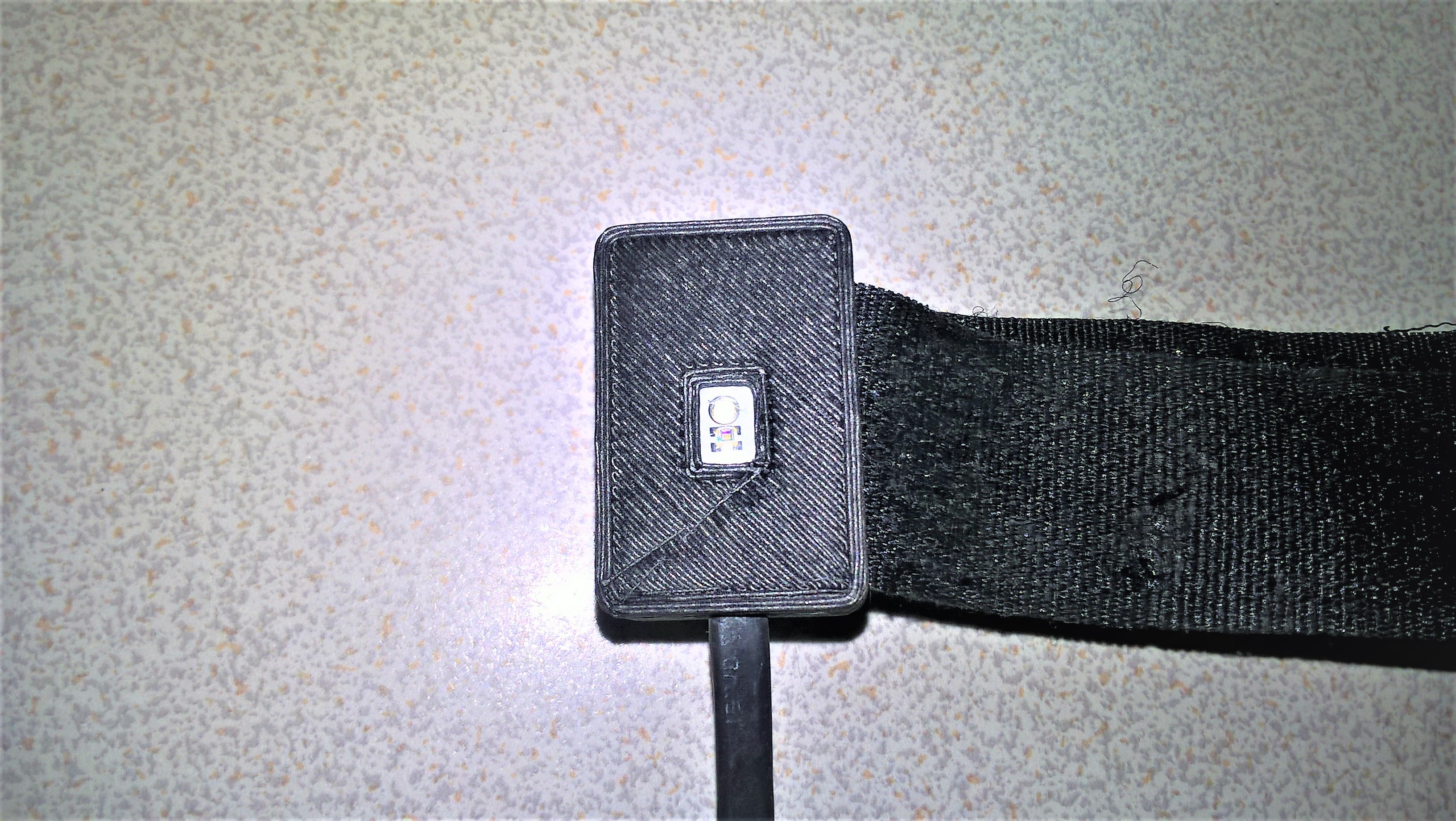
    The cover of sensor comes in two parts with position guide

    The sensor cable must be covered whit heat shrink. At the end it would be this way

    The union with the socket and the arm it was print with flexible filament

  • 3
    Power Management

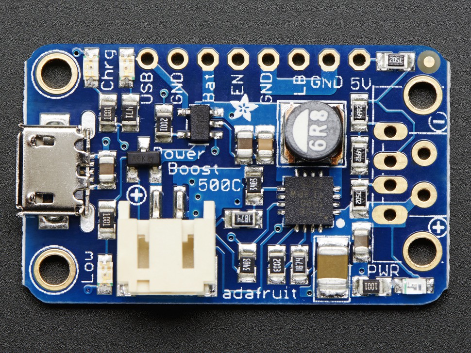
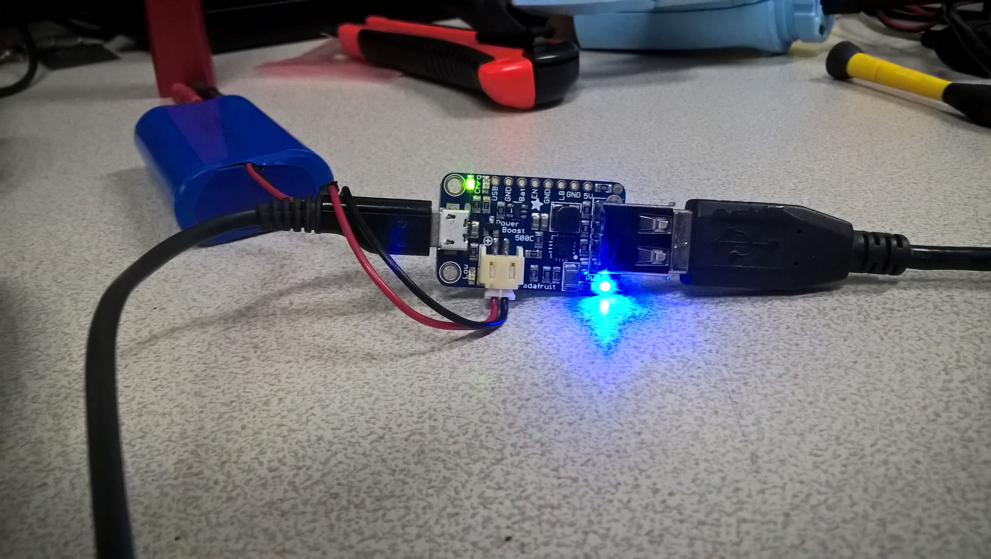
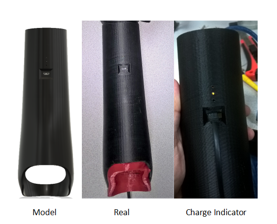
    For the power management we decided use the the Power Boost 500 de Adafruit https://www.adafruit.com/product/1944,  however, we talk about use the Power Boost 1000 for a best current . This circuit is a great option since it charges the battery fast, has 5 volts constant output also have a very useful led indicators.

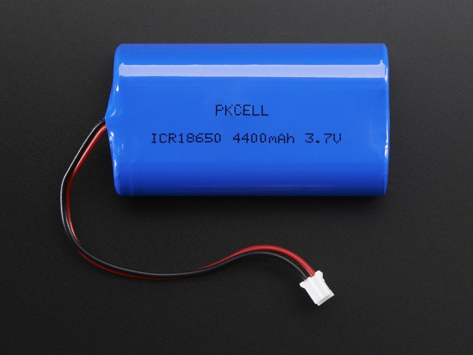
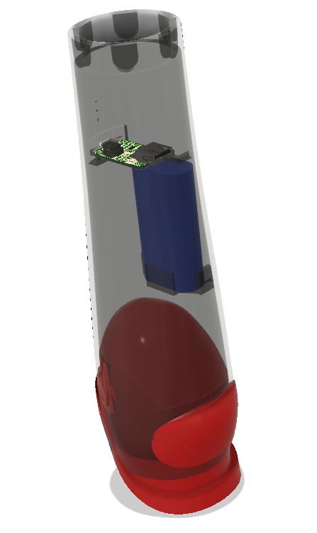
    The Battery is a Lithium Ion Battery Pack - 3.7v 4400mAh of Adafruithttps://www.adafruit.com/product/354 its of heavy duration and great peak current capacity. The Socket have a battery box  in the model.

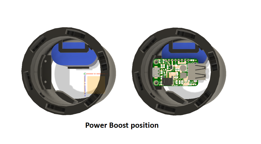
    The Socket have a specific position for the Power Boost because the input of the charge is predefined 

    The input of charge is a micro usb type, and is compatible with the most common usb chargers. 

    Thanks to the power boost we have an overload protection.

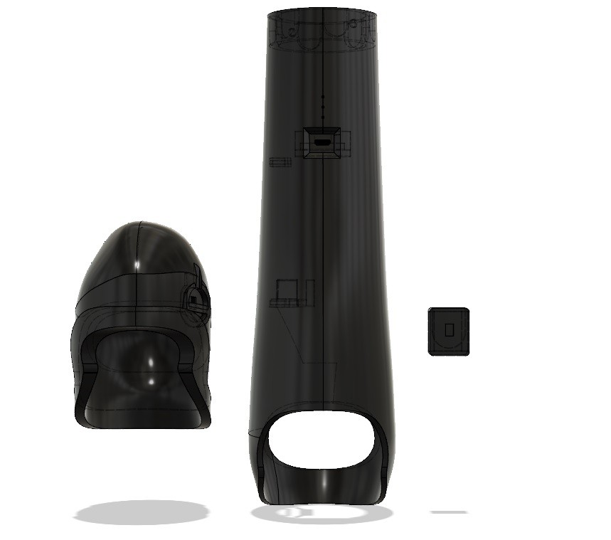
    The position of the components in the socket is a visible in the next image

View all 5 instructions

Enjoy this project?

Share

Discussions

Similar Projects

Does this project spark your interest?

Become a member to follow this project and never miss any updates