-
1Checking to start
First check the you have necessary materials to make the project. You need some 3D printed parts, so a printer is necessary or at least the posibility of print. We print with protopasta carbon fiber filament but you can print in PLA, thats if you want to strap the sensor to your arm. If you want to embed the sensor to a socket we recommend to use a flexible material as NinjaFlex. Also you need a Pulse Sensor Amped from Adafruit or compatible. The whole hand part, you may go to this article https://hackaday.io/project/13339-tns-1i, this article is the base of the hand what we used, if you read the article will see what need various components as adafruit feather board among others . The models of the parts is in the Files section.

-
2Printing
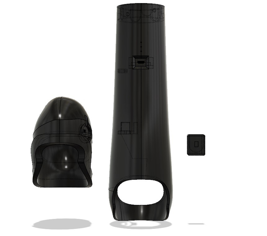
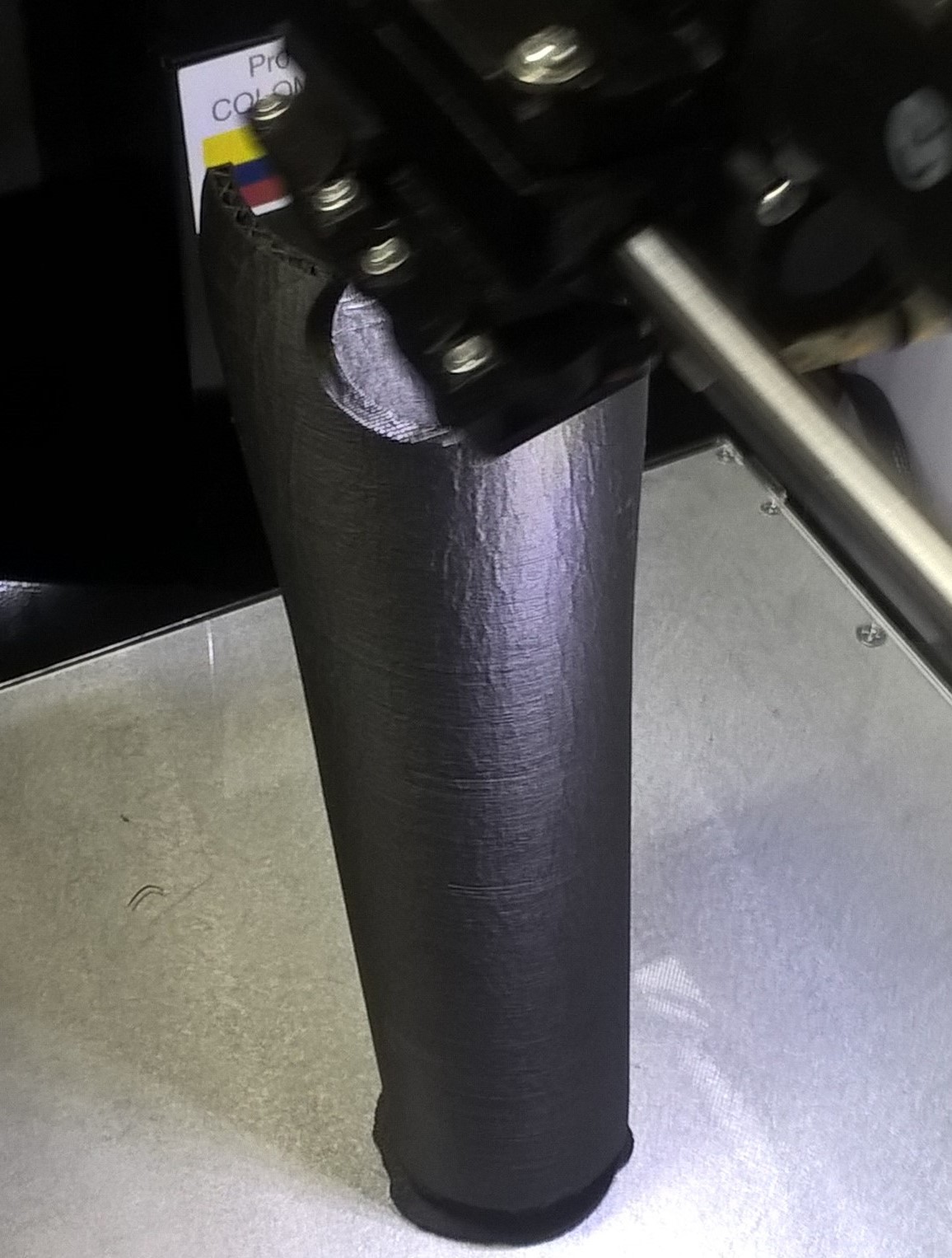
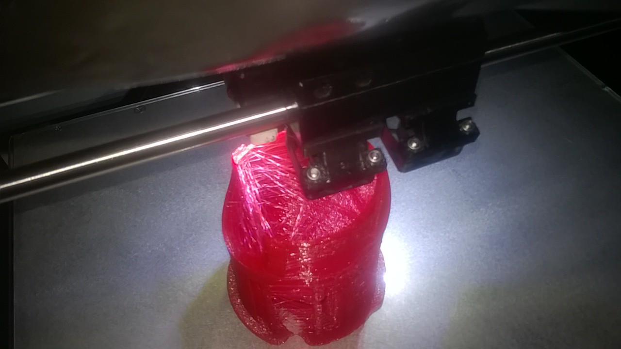
After the checking, you need print the parts, you may download the stl files and print. The Encaje socket you must print it in flexible filament, the other parts can print it in your filament of preference, we print with Protopasta carbon fiber.

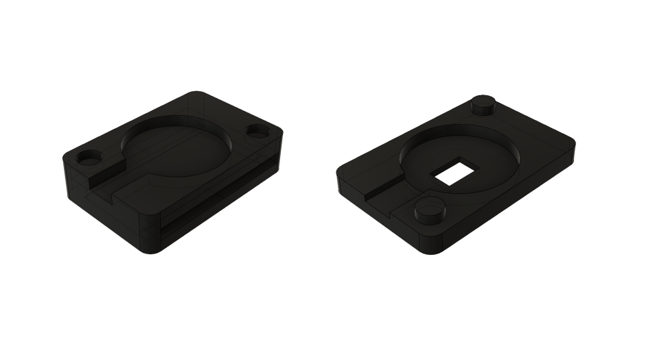
The cover of sensor comes in two parts with position guide

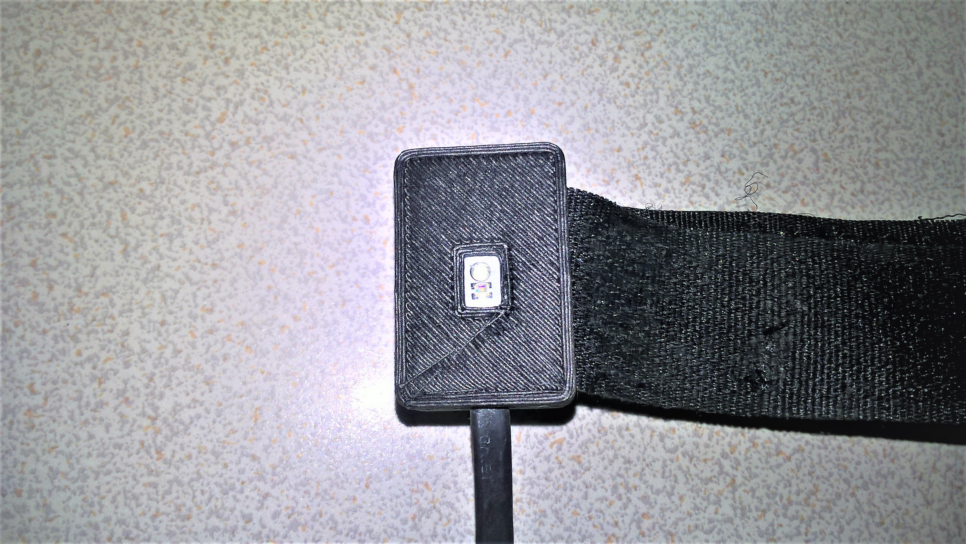
The sensor cable must be covered whit heat shrink. At the end it would be this way

The union with the socket and the arm it was print with flexible filament

-
3Power Management
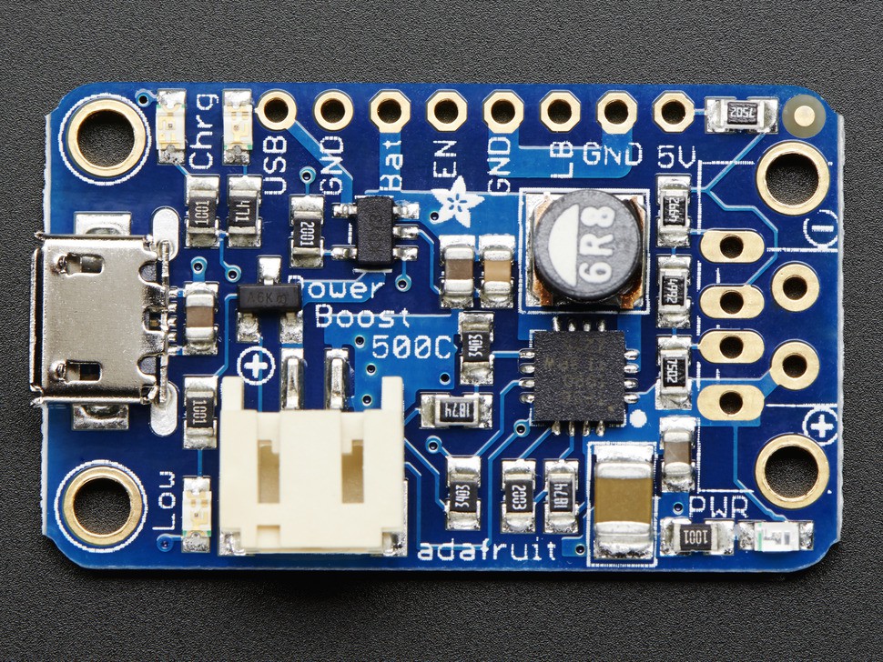
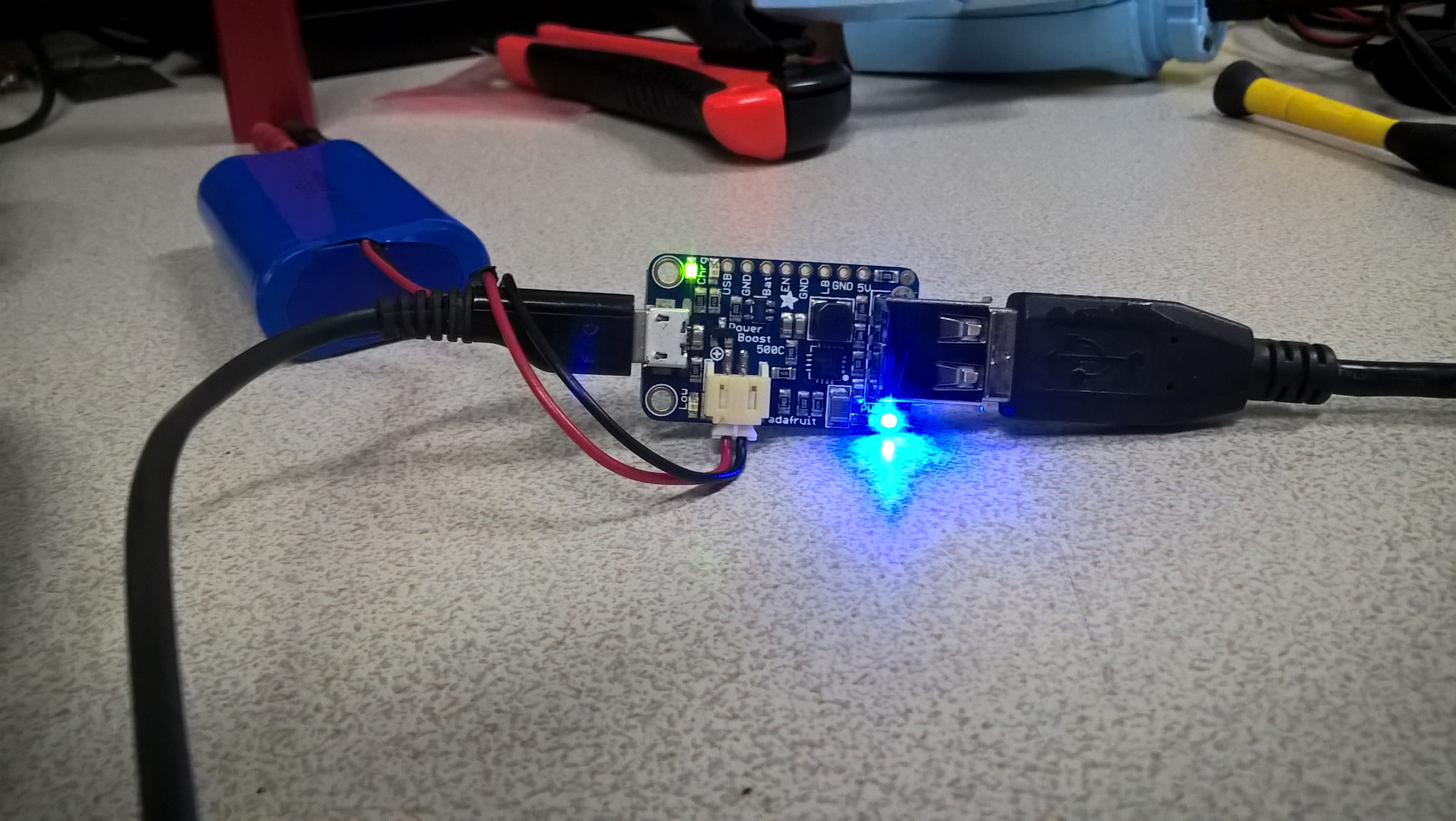
For the power management we decided use the the Power Boost 500 de Adafruit https://www.adafruit.com/product/1944, however, we talk about use the Power Boost 1000 for a best current . This circuit is a great option since it charges the battery fast, has 5 volts constant output also have a very useful led indicators.

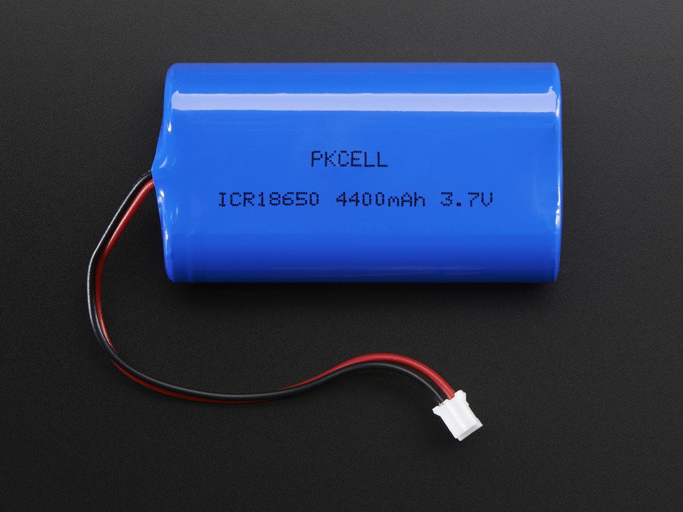
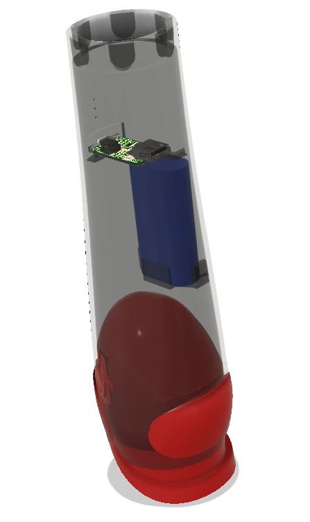
The Battery is a Lithium Ion Battery Pack - 3.7v 4400mAh of Adafruithttps://www.adafruit.com/product/354 its of heavy duration and great peak current capacity. The Socket have a battery box in the model.


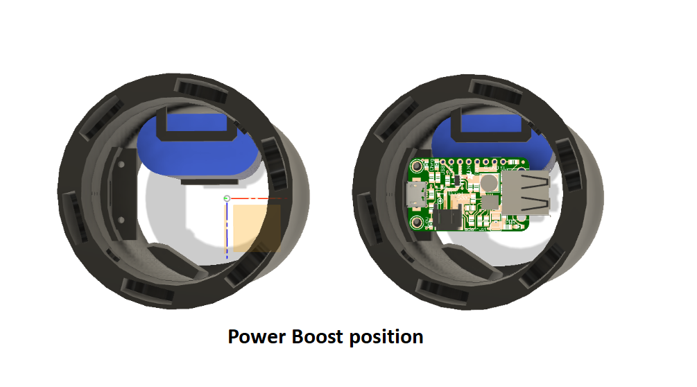
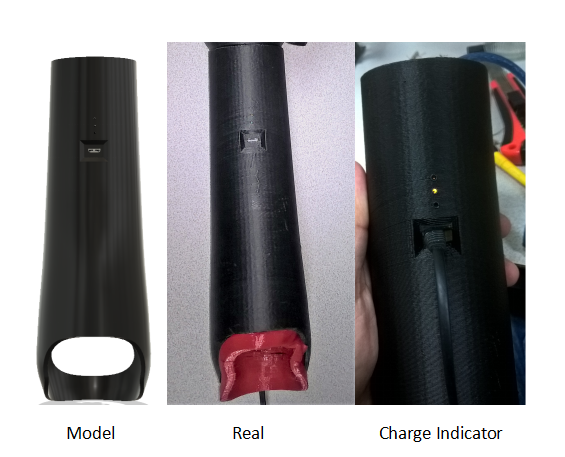
The Socket have a specific position for the Power Boost because the input of the charge is predefined

The input of charge is a micro usb type, and is compatible with the most common usb chargers.
Thanks to the power boost we have an overload protection.

The position of the components in the socket is a visible in the next image

-
4Connections
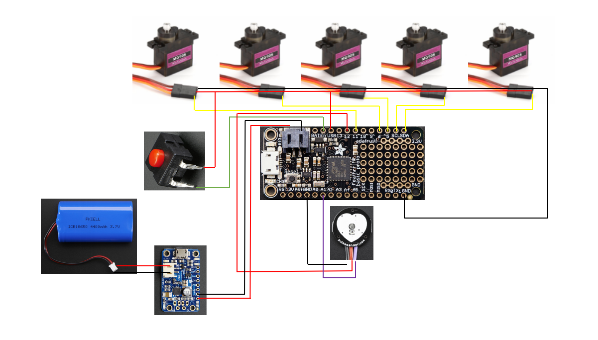
Inside the Hand have a Adafruit Feather 32u4 basic proto board https://www.adafruit.com/product/2771, this board have all necesary for the control of the hand, also have four Pololu motor, one servomotor and the power button, inside the socket are the battery and the power boost, and at the end have the pulse sensor. In the next image we can see the connections diagram.

The reason of show five servomotors you can see in the next link https://hackaday.io/project/156520-3d-printed-mini-linear-actuator where is explained the way of use a pololu motor with the servomotor.
-
5Sensor calibration
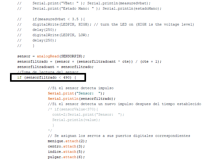
When the hand its ready the next step is the sensor calibration, the arduino code has one variable for this purpose, this variable is named "sensorfiltrado". If the condition of variable "sensorfiltrado" its modify, you can change the sensibility of sensor, its means that you have to make a bigger o smaller movement with the muscle to operate the hand.

In this case the condition its minus of 490, but it depend of each person.
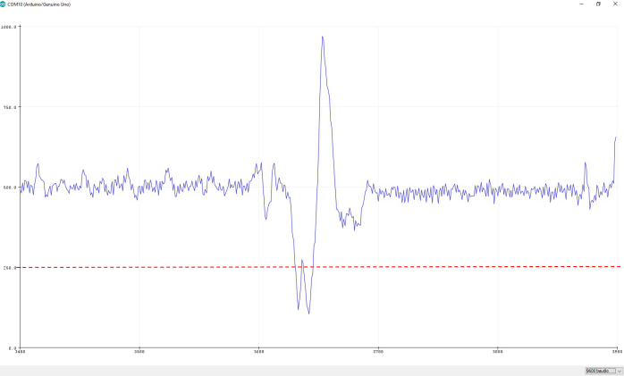
For example in ths next case we could say that if the variable is less than 250 it is activated, because the signal its less than 250, we take the peak of the signal down as activator

Pulse sensor to actuate a Robotic Hand
We are trying to implement a pulse sensor to actuate a 3D printed prosthesis instead of the myoelectric ones. That's a first, we think.
 Giovanni Leal
Discussions
Become a Hackaday.io Member
Create an account to leave a comment. Already have an account? Log In.