deʃhipu
-
Complete Prototype
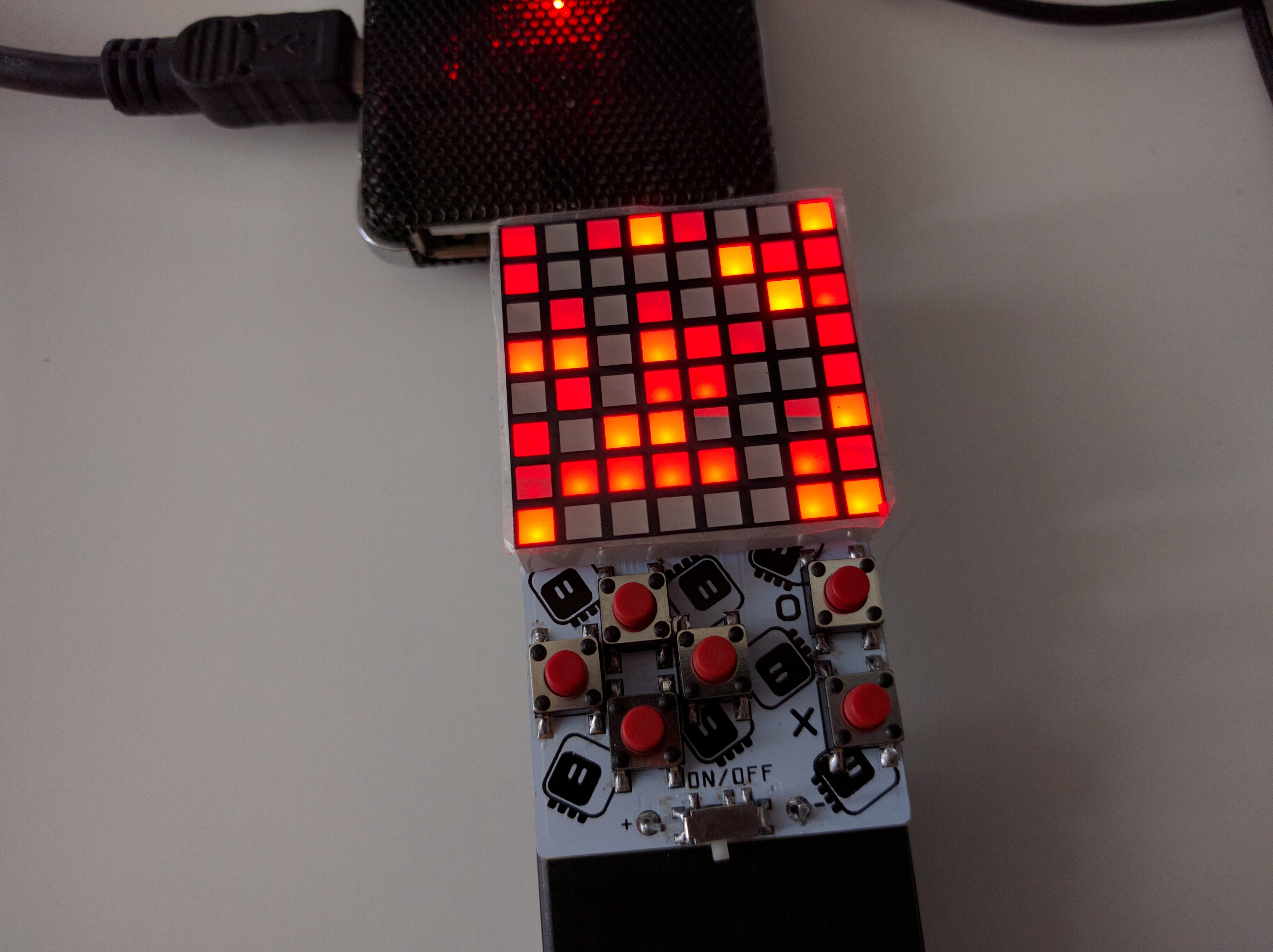
08/04/2018 at 16:57 • 3 commentsThe battery holders finally arrived, so I replaced the temporary one with a proper one. I must say they are flimsier than I expected, but I suppose I can't complain at this price.
![]()
With the device finally physically complete, I got to test how well it lies in the hands and how convenient it is to play on it. I have to say I'm not impressed. The two AA batteries add considerable weight and thickness, which together with the relatively small size of the device and closeness of the buttons doesn't work very well. It's not as bad as some handhelds I have seen, but could be better.
I'm thinking about switching to horizontal arrangement again, with the buttons on both sides of the display. Also, thinking about AAA batteries — they would be enough for a few days of playing still, but a bit lighter. They are slightly more expensive, though.
-
Here We Go Again
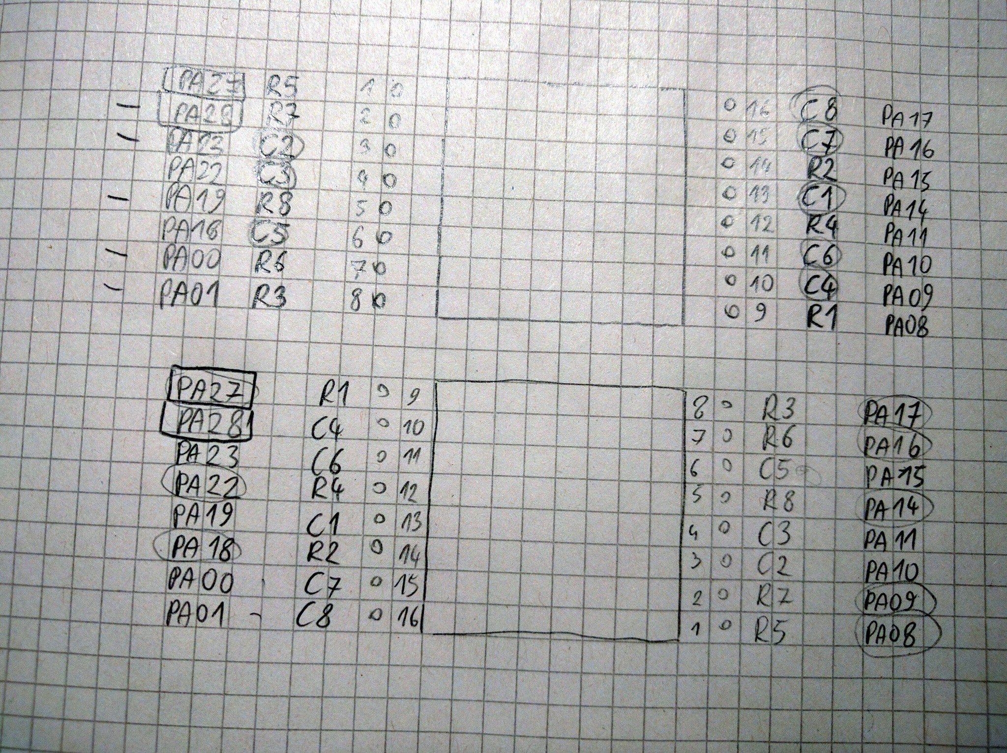
08/01/2018 at 20:17 • 0 commentsIn the previous log I mentioned that I need a better solution to dim the LEDs — the system tick interrupt doesn't fire fast enough for me to have a good enough refresh rate to do it in software. I decided that I will do this by using PWM on the row pins — I can make the PWM frequency high enough that it won't interfere with the column scanning, and then I have a really nice 16-bit range of shades. However, there is a small problem with this: two of the row pins are connected to GPIO ports that don't support PWM. The culprits are R5 (PA27) and R7 (PA28). I checked if I could perhaps solder the matrix up-side-down to make those pins be connected to columns instead, but no, it works for PA28, but PA27 is then connected to R1.
![]()
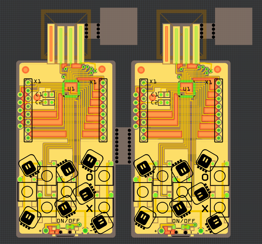
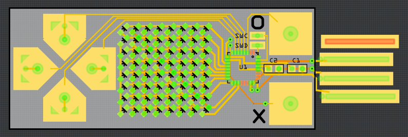
So I have no choice: a new PCB design is needed. To be honest, that was coming anyways, as the spacing of pads in the USB plug wasn't perfect, and I wasn't proud of the right-angle traces. So I removed the connections, rotated the microcontroller by 90°, and re-connected everything, paying attention to use PWM-capable pins for the rows. I think it came out much cleaner this time:
![]()
The "forbidden" pins, PA02, PA03, PA27 and PA28 are all used for buttons now. I will mull over the design a little bit more, and order it from OSHPark this time.
-
Driving the Matrix
08/01/2018 at 17:34 • 0 commentsThe whole point of building this device is cutting the costs, and the two main tricks for it are using a single-color matrix and simulate the 4 colors with 4 shades, and driving the matrix in software directly from the microcontroller. Obviously, for this to work I need to write the code that would drive the matrix and that would let me display 4 recognizable shades.
Turns out this is more difficult than anticipated.
Initially I thought that I will simply plug the matrix-driving function into the system tick interrupt of CircuitPython. Something like this:
void pew_tick(void) {
    digitalio_digitalinout_obj_t *pin;
    pew_obj_t* pew = MP_STATE_VM(pew_singleton);
    if (!pew) { return; }

    pin = MP_OBJ_TO_PTR(pew->cols[pew->col]);
    common_hal_digitalio_digitalinout_set_value(pin, true);
    pew->col += 1;
    if (pew->col >= pew->cols_size) {
        pew->col = 0;
        pew->turn += 1;
        if (pew->turn >= 3) {
            pew->turn = 0;
        }
    }
    for (size_t x = 0; x < pew->rows_size; ++x) {
        pin = MP_OBJ_TO_PTR(pew->rows[x]);
        uint8_t color = pew->buffer[(pew->col) * (pew->rows_size) + x];
        if (
            ((color & 0x03) == 0x03) ||
            (color & 0x01 && pew->turn == 0) ||
            (color & 0x02 && pew->turn > 0)) {
            common_hal_digitalio_digitalinout_set_value(pin, true);
        } else {
            common_hal_digitalio_digitalinout_set_value(pin, false);
        }
    }
    pin = MP_OBJ_TO_PTR(pew->cols[pew->col]);
    common_hal_digitalio_digitalinout_set_value(pin, false);
}
This works reasonably well. There are two problems, though. The system tick happens once every millisecond, so the least bright pixel is getting 41Hz refresh rate (it's only one once every 3 frames, and there are 8 columns to scan). That's slow enough that some blinking is visible. The other problem is that the two brightest shades are really difficult to tell apart — that is because human eye is logarithmic in its sensitivity, so to get good shades, I would need to put them on a logarithmic scale. That means that I need more than just 3 frames, and that makes the least bright shade blink even more.
I can think of three ways of fixing this problem.
The easiest and most hacky way, that I actually tested already, is to simply increase the speed of the system tick timer. Of course that has a side effect of all time-keeping functions also increasing in speed, but we could adjust for that. I'm not sure how much I can increase it before other side effects kick in, though, and I don't like how hacky that is.
The second easiest solution would be to use PWM on the row pins to control the brightness. I can set it to a pretty high frequency, and then refreshing the 8 columns could be done at 125Hz, which is enough for not seeing them blink. I would also get a really smooth scale of shades then. The problem is that my choice of pins for the rows was somewhat random, and not all of them support PWM — so I would need to design a new PCB. I might be able to work around this by rotating the matrix 180° — I need to check if then all the row pins support PWM.
Finally, the most "correct" solution would be to leave the system tick timer alone, and use a dedicated timer with a separate interrupt for doing this. Unfortunately that requires a little more skill than I have at the moment, but perhaps I could learn.
![]()
-
A Prototype
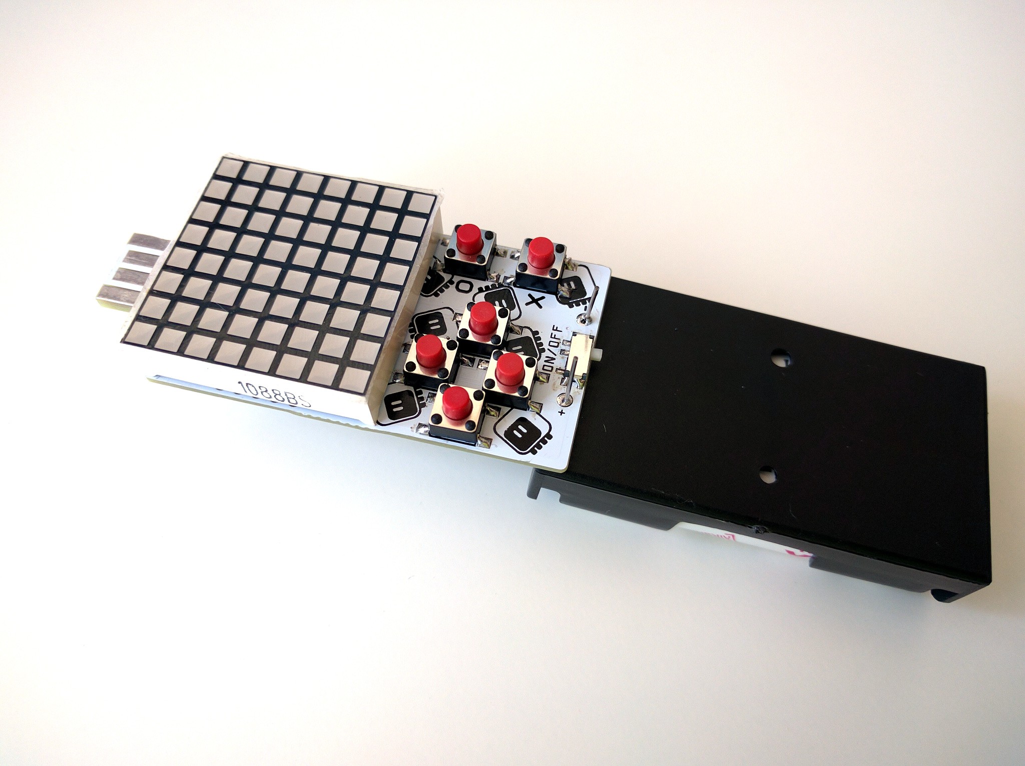
07/31/2018 at 21:17 • 0 commentsThe boards arrived when I was travelling, and now that I am home again, I can actually work on this again. As a start, I assembled one of them:
![]()
I am still waiting for the battery holders — in the mean time, I used one that I had available, which has the + and - reversed — that's why it's soldered wrong. That's actually convenient, because it gives me access to the programming and reset pins under the matrix. Of course the final version will have the batteries under the device.
The USB plug works, but I think I made the pads a bit too wide and the spacing too large — they have a good contact, but it's lost when you wiggle the device.
I have the CircuitPython firmware with the custom pin definitions and increased internal disk size flashed. The next step is to write the matrix-driving code in Python, to test it, and then to rewrite it in C as part of the firmware, so that it can run in the background. I was hoping to start on that today, but there was no time this evening. Tomorrow is a holiday, so I hope to get that working then.
-
Boards Ordered
07/16/2018 at 18:20 • 2 commentsI just made a few last-minute fixes, and ordered the boards for DirtyPCBs. Their shipping seems to be working again, and I want to support them for not caring about how your project is panelized and how many "distinct" designs there are.
![]()
I decided to use white PCBs again, mostly because the matrix's outside is white too, and because I found white battery holders on Aliexpess. I used a cheap shipping option, so it will be a few weeks — which is totally fine by me, because I'm going to the Europython conference next week anyways.
I also added those tiny squares there, which I'm going to glue under the USB plug. Since the PCB is 1.2mm thick, this will get me to the required 2.4mm thickness.
-
A Series of Insights
07/15/2018 at 19:19 • 1 commentToday has been a rollercoaster of emotions — I blame not getting enough sleep last night. Basically every time I finished some part of the design, I had a new great idea that required me to redo everything from scratch, and as soon as I did that, I had a new idea, etc. — until I made a full circle and ended up with something very close to PewPew 5.0, only with fewer parts. In the process I had to ditch the business card idea, so I renamed this project now. But let's go through it in order.
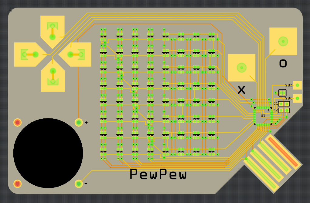
As I wrote in the previous log, I spent the night routing charlieplexed 16×8 matrix of bi-color LEDs. But following the "no PCB orders after midnight" gremlins rule, I decided to let the design sit for a bit and mature. In the morning I realized that since I'm driving the LEDs in software I have more flexibility than a simple on/off, and that therefore I can replace the four colors of the original PewPew with shades of the same color in the cheap version. That reduces the costs considerably, because not only single-color LEDs are much cheaper than bi-color ones, but also I only need to charlieplex 8×8 LEDs, which can be done with 9 pins. I can also make the whole thing much smaller. So I designed this:
![]()
I didn't make a proper board outline to account for the USB plug, and the battery is missing — it would go on the back. There are some problems with this design, though: the whole thing is simply too small, the touch pads are too close to each other, and the display is too small (also, I put the vias on the footprints of the LEDs, which allegedly can be problematic when using solder paste).
So I kept thinking and experimenting. I could use larger LEDs, but they are more expensive and usually take more current. I could put the LEDs on the back of the board, up-side-down, and have square windows in the copper and soldermask — but a quick experiment with a word clock PCB that I got from @davedarko made me realize that I really don't want to solder a lot of tiny LEDs up-side-down. I looked for "bottom view" LEDs, but they seem to be designed to be inserted into holes in the PCB.
Then a second realization struck: if I'm not using bi-color LEDs, then I can simply use a monochromatic 8×8 LED matrix — not only it is cheaper than all those LEDs, not only it's infinitely easier to solder, not only I have a whole bunch of them lying around, not only they actually have square pixels, but also I have exactly 16 free pins, so no charlieplexing is necessary.
In the mean time I also made a series of experiments with batteries, and realized that unless I use a rechargeable coin cell battery, it's not going to be able to power this device. I looked at the prices of different batteries out there, and I decided that if this device is supposed to be cheap and accessible, then I need to use AA alkaline batteries. Which of course defeats the whole idea of a flat business card.
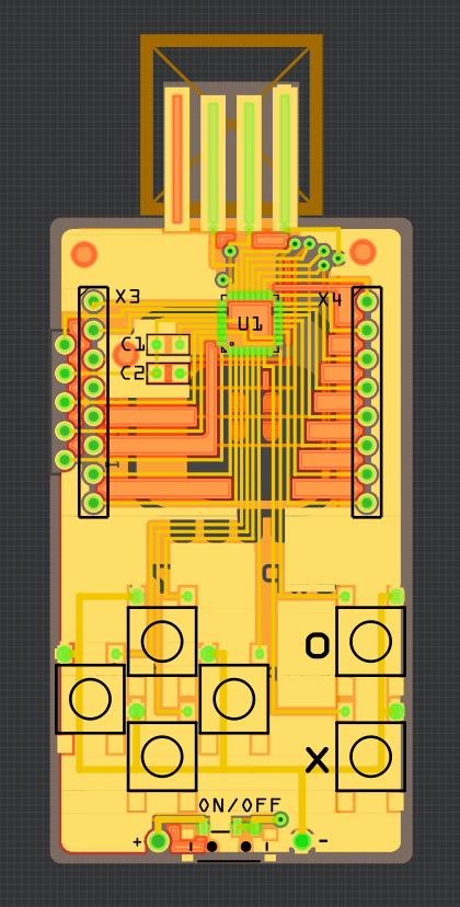
So a thicker device, the size of a 2×AA battery holder, with the said holder on the back, and with a 32×32mm matrix on the front. But the matrix is quite thick too, and that makes using touchpads awkward. Hmm, let me check again how much those buttons cost? Oh, I got 1000 pieces for $16. I suppose I can as well put them back. And a power switch too, because sleep modes of SAMD21 are not yet that well supported in CircuitPython. Hmm, ok, so where does that leave us? Basically here:
![]()
It looks pretty much the same as PewPew 5.0, but has 2x fewer parts and is proportionately cheaper. Of course I still need to write the code that will drive the matrix — it has to live in a timer, so I can't write it in Python, it has to be compiled into the firmware — but that should be easy. Now, according to my rough calculations, materials for making 20 pieces of this should cost me around $60, with shipping. Add assembly costs, handling and some margin for unforeseen circumstances, and I should be able to sell them at the same price as the original PewPew Lite FeatherWing! Shipping may be problematic, considering the thickness of the whole thing, but maybe if the battery holder is separated...
Anyways, let's not get ahead of ourselves. A lot of work remains to be done.
-
First Attempt at Routing
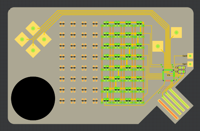
07/15/2018 at 11:20 • 0 commentsSince I couldn't sleep this night, I took a stab at routing this 16×8 matrix. I decided to split it in two parts, one 7×8 and one 9×8, rotated by 90° — this time I have the whole thing covered with 17 pins, but I can scan the whole thing in just 8 steps instead of 12. I only had 16 free pins, but I re-used the programming/debugging pins (with a jumper to disconnect them from the LEDs for programming). I also fixed the USB plug and made the button pads a bit bigger.
![]()
I still don't look forward to soldering the prototype manually...
-
How Lite can PewPew be?
07/14/2018 at 23:28 • 7 commentsAfter designing a cheaper version of the #PewPew FeatherWing recently, I started thinking: what if instead of using a separate chip for driving the LED matrix, I used the free pins on the MCU? And instead of buttons use touch pads? And instead of a USB port use the shape of the PCB? I could get the BOM literally to a few parts!
One problem with that: I would need 24 pins to drive the bi-color matrix. Sure, I could add shift registers and decades and whatnot, but then I'm back to using additional chips, and with the price of the HT16K33, I may just as well use that. But what if I could use fewer pins? Are there tricks for that?
With charlieplexing I could drive a 16×8 matrix with as few as 12 pins (the formula is n²-n, which for 12 gives me 132 LEDs, four more than my required 128). But you can't charlieplex matrices with common cathodes. Well, you can, but that's not useful for square matrices. But what if I made my own bi-color matrix on the PCB? You can get 0603 bi-color LEDs cheaply — in fact cheaper than the equivalent matrix. Soldering them is a lot of work by hand, but if I got it fabricated the pick-and-place machine does all the work anyways. And it would then be flat. Like a business card.
Wait a minute...
With so few parts it could actually be cheap enough to use as a business card!
So I made this mockup:
![]()
The big black hole is for a CR2032 battery — it will be sunken into the PCB, to keep the thickness at a minimum.
I even started routing the matrix — for now I have routed 8×8 LEDs with 9 pins used, and 7 pins free. Now I have two options: route the other half the same way, using the remaining 7 free pins, and the two debugging pins (possibly with some jumpers to disconnect them for debugging), or redo the whole thing as a 12×11 matrix using only 12 pins, and then rearrange the LEDs back to 16×8. Of course the second option would be much better, but I'm not sure I have the stamina for that. If I go for the 2×8×8 approach, I might also separate the two colors — we will see how it goes.
PewPew Standalone
A Python-based micro game console, optimized for game development workshops.