-
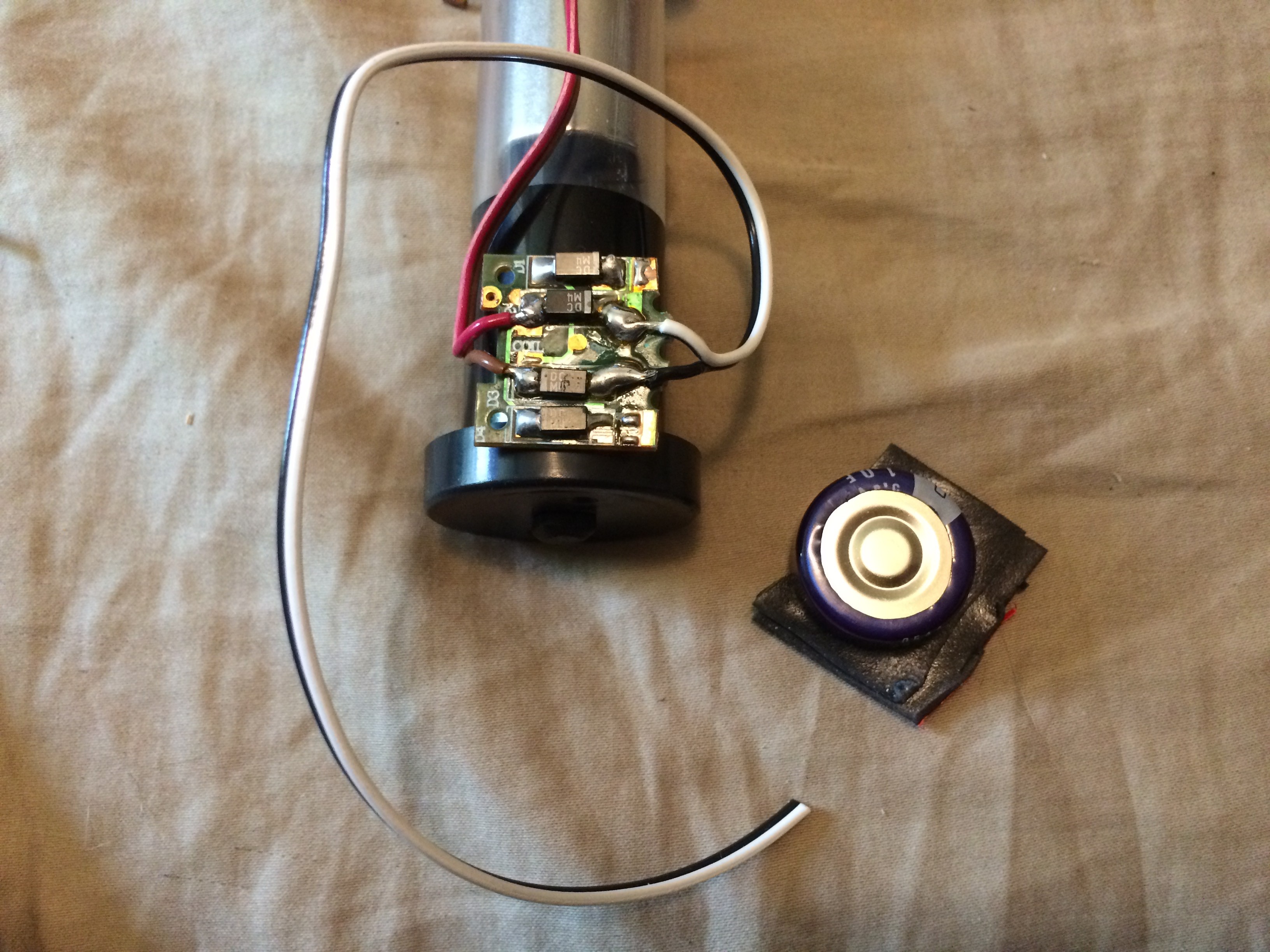
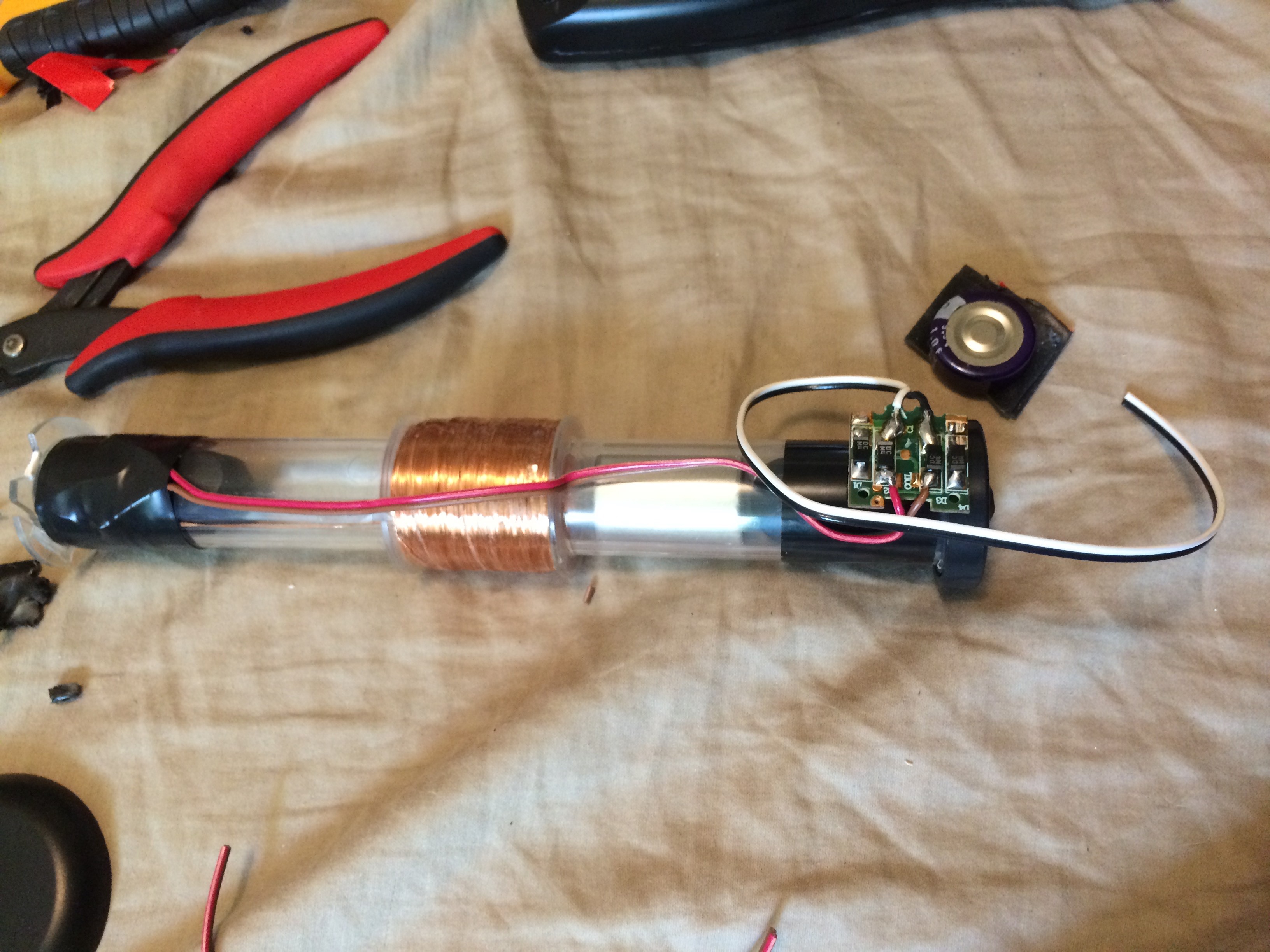
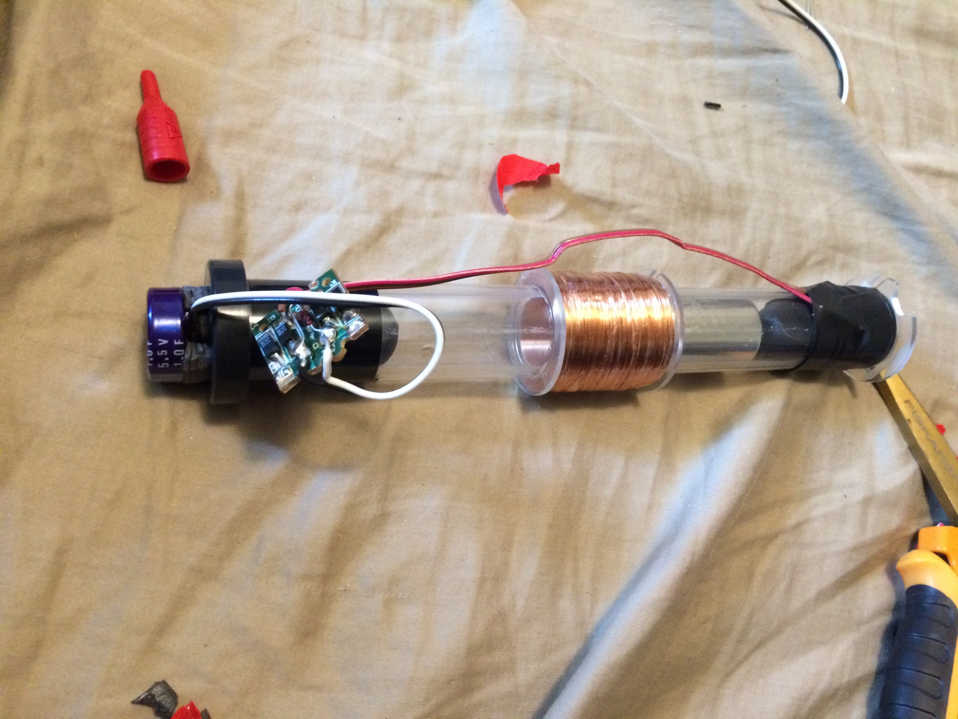
11Position the rectifier board at the bottom of the coil assembly.
![]()
-
12Protect the soldered coil wire connections with electrical tape.
![]()
-
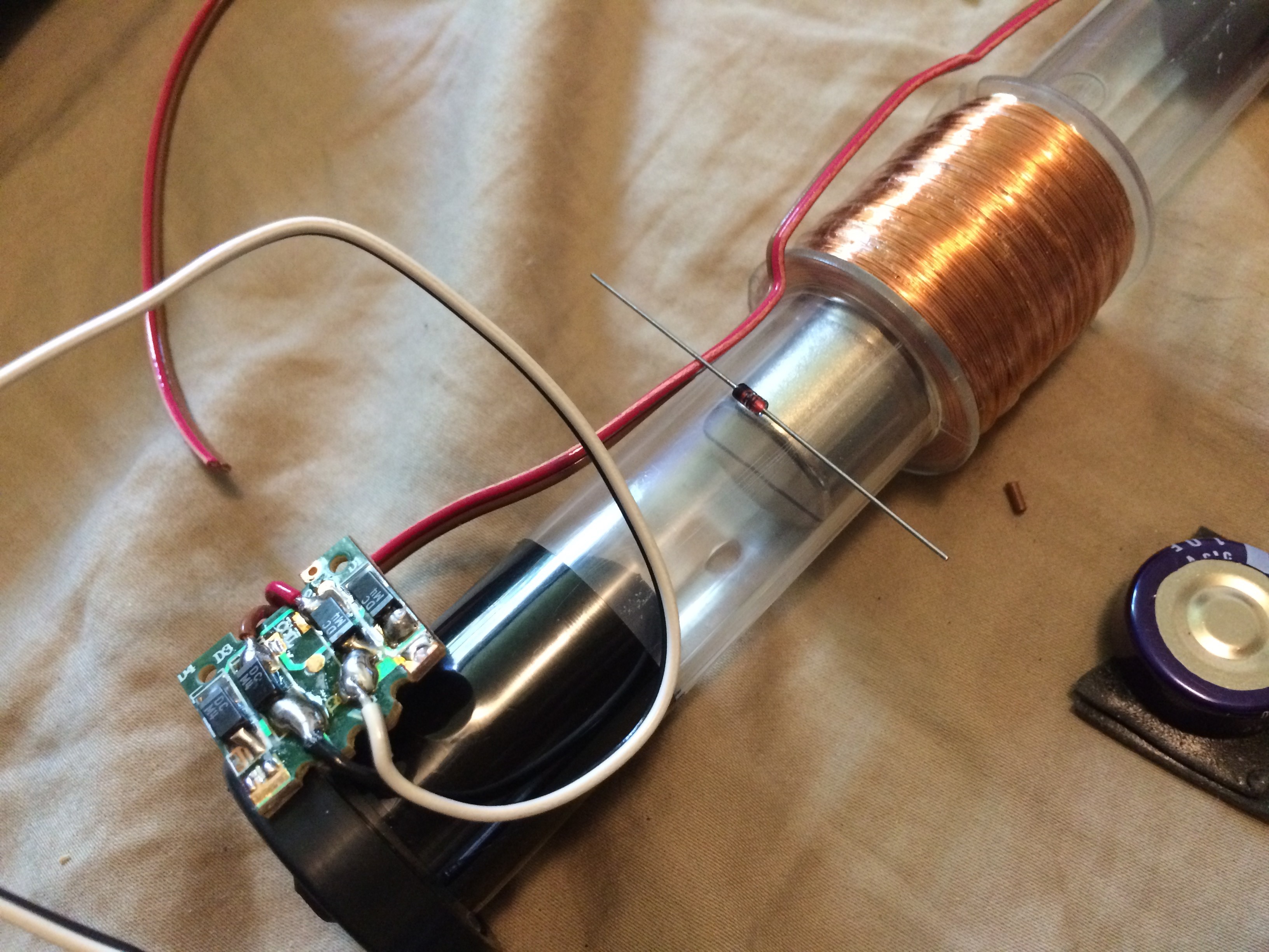
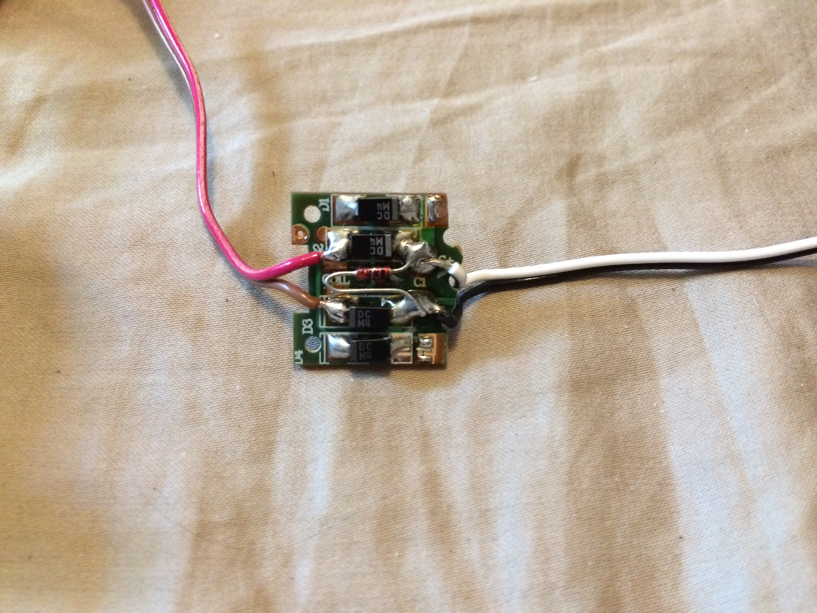
13Optional (part 1): Add add a Zener to the diode bridge output to protect from over voltage (too much shaking...).
![]()
-
14Optional (part 2): Fit and solder diode to the output and snip off excess.
![]()
-
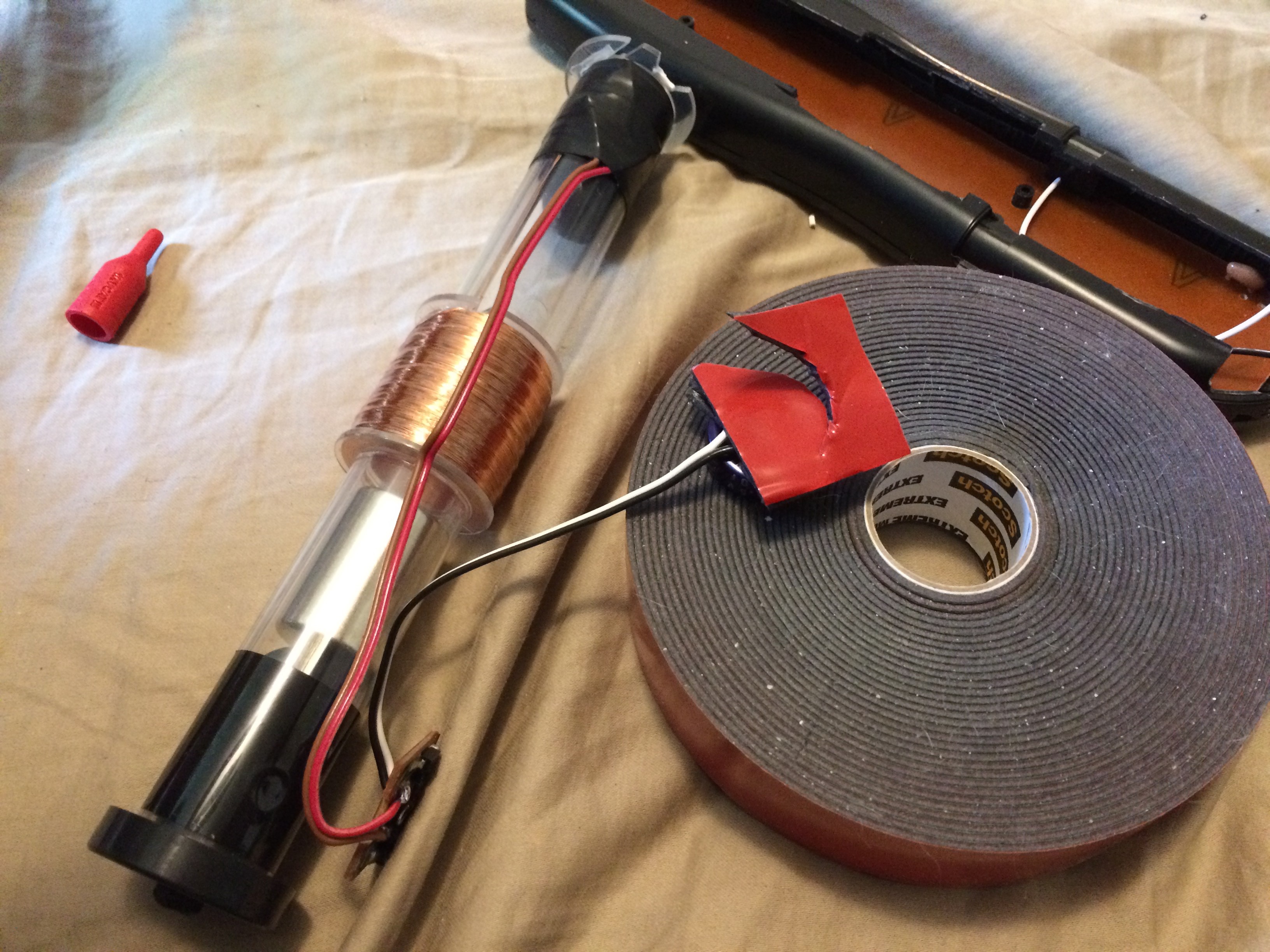
15Add a few layers of double-sided foam tape to the capacitor and trim to size.
![]()
-
16Stick the capacitor on the bottom. Make sure there is room for the entire assembly to fit into the remote casing; if it will not, cut a hole in the casing to accommodate the capacitor.
![]()
-
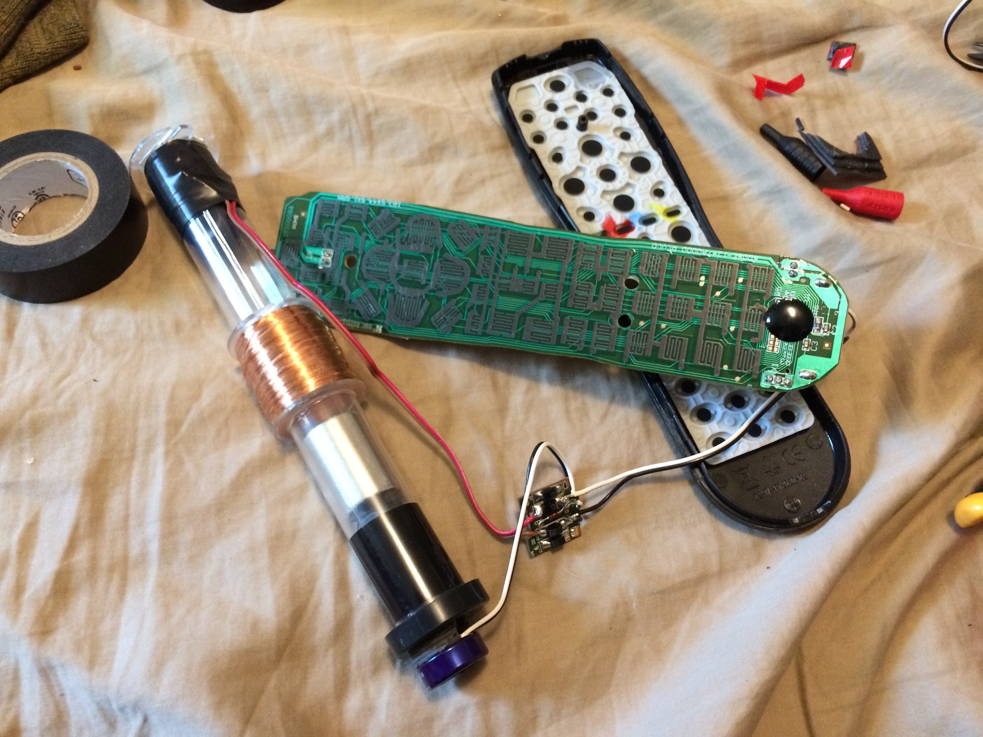
17Grab your remote innards.
![]()
-
18Remove the battery contacts from the remote circuit board and attach the wires from the diode bridge output.
![]()
-
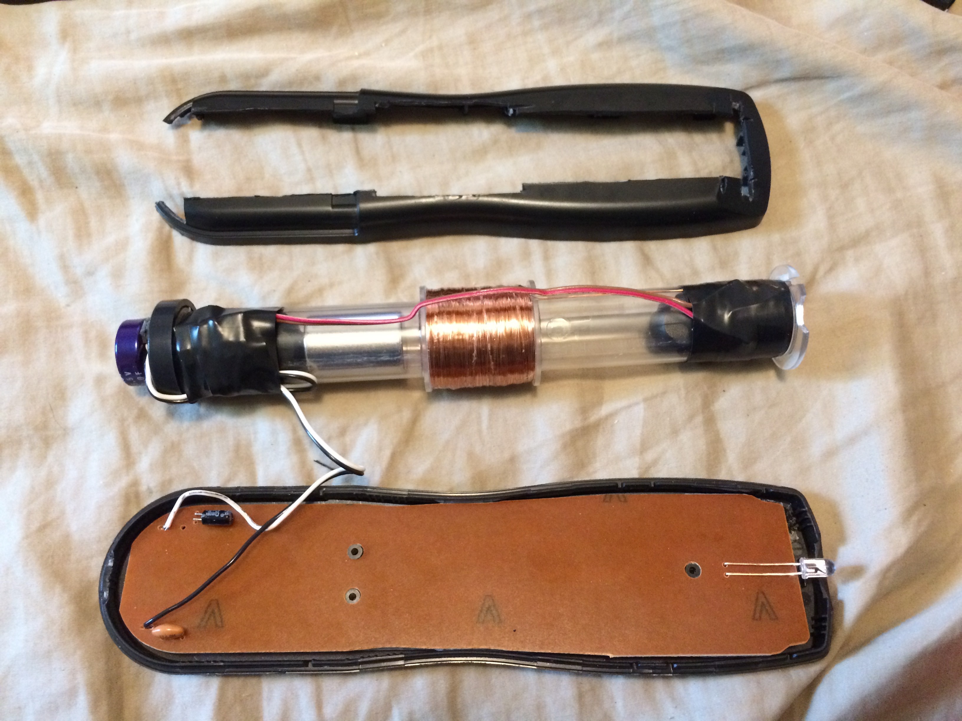
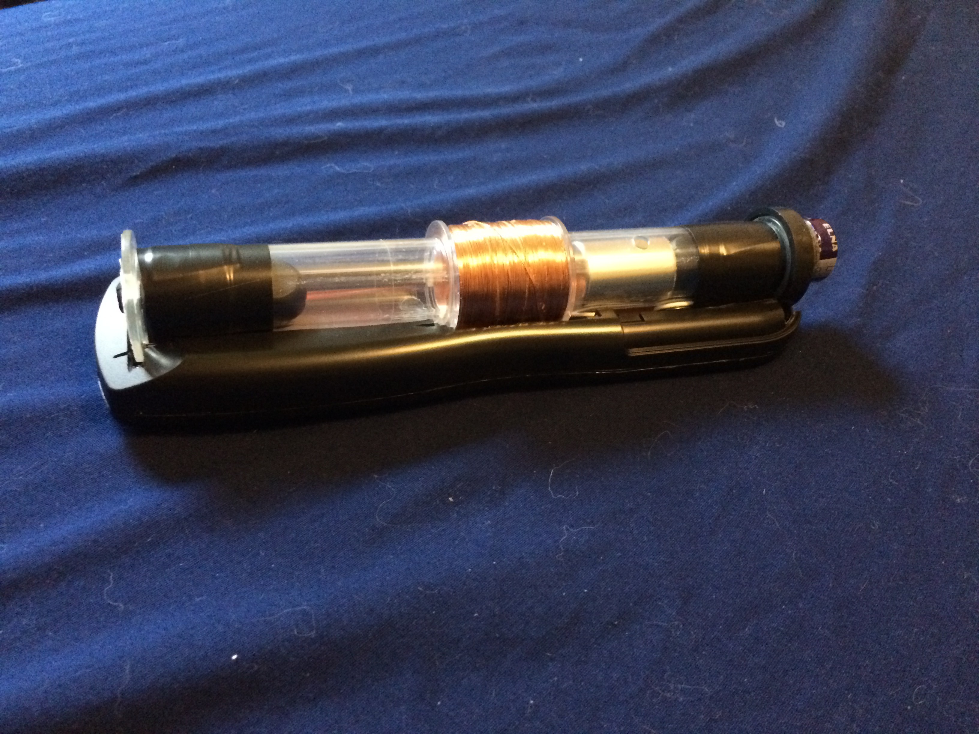
19Assemble everything, ensuring it all fits nicely.
-
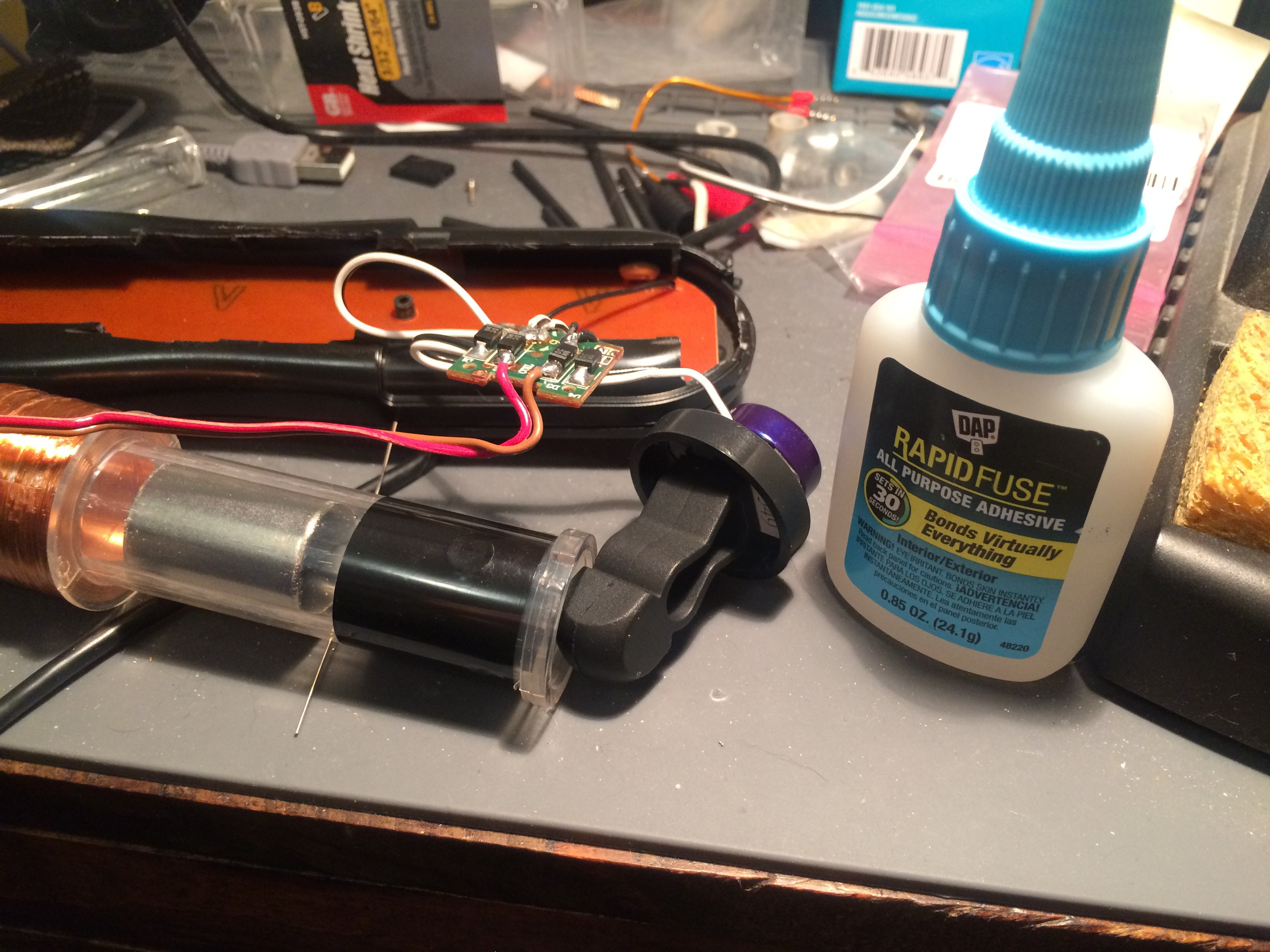
20Prepare to glue the bottom cap on the coil assembly. I used this glue because it contains ethyl cyanoacrylate which has some flexibility.
The Undead Remote
The mutant offspring of a shake flashlight and a universal remote.
 oneohm
Discussions
Become a Hackaday.io Member
Create an account to leave a comment. Already have an account? Log In.