-
1Development instructions for LDR circuit
- LDR circuit:
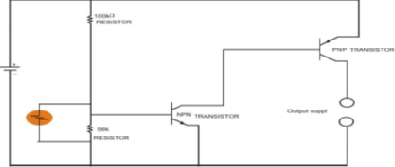
- The LDR circuit consists of a light dependent resistor and a class B amplifier arrangement. The class B amplifier arrangement is just a combination of PNP (positive-negative-positive) and NPN (negative-positive-negative) transistors which are so matched that the PNP transistor is biased (conducts electricity) for half cycle and NPN transistor is biased for the second half cycle of the input. Circuit diagram 1 shows the LDR circuit. The output from the LDR circuit is recorded by IC 555. The LDR circuit arrangement should be as follows:
- LDR circuit:
Circuit diagram-1
- At the “sun-bright” position, LDR shows low resistance due to high intensity light falling on it. As a result, the base of the NPN transistor receives high negative voltage as per circuit diagram. This causes the NPN transistor to remain turned off and it does not conduct any current. However, the PNP transistor remains biased and allows the flow of current from it which contributes towards the output supply. This output resets the IC 555 and triggers the DC gear motor to stop. Hence, the reception surface or frame stops at the sun-bright position.
- In case the frame is not in sun-bright position, the LDR shows high resistance due to low intensity light. However, this time NPN transistor gets low positive voltage from the main positive line. As the output from the NPN transistor is turned on, the output from the PNP transistor is cut off and the IC 555 is reset again which triggers the DC gear motor to move the frame till the maximum intensity light is found again.
-
2Development instructions for magnetic proximity circuit
- Magnetic Proximity Circuit:
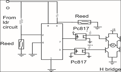
- The magnetic proximity circuit comprises of an IC 555, two reed switches, two magnets attached behind the frame and a H-bridge arrangement. The H-bridge arrangement is a combination of 4 NPN transistors or switches in general that enable a voltage to be applied across a load in opposite direction. It is crucial in switching the polarity of DC gear motor and reversal of the motion of frame. Reed switches are switches which can turn on or off when subjected to a magnetic environment. Circuit Diagram-2 shows the magnetic proximity circuit.
- The magnetic proximity circuit comprises of an IC 555, two reed switches, two magnets attached behind the frame and a H-bridge arrangement. The H-bridge arrangement is a combination of 4 NPN transistors or switches in general that enable a voltage to be applied across a load in opposite direction. It is crucial in switching the polarity of DC gear motor and reversal of the motion of frame. Reed switches are switches which can turn on or off when subjected to a magnetic environment. Circuit Diagram-2 shows the magnetic proximity circuit.
- Circuit Diagram 2
- In the magnetic proximity circuit, the output from the LDR circuit is received by the IC 555. The output from the IC, connected to the DC gear motor via pin number 3 and 7, controls the motion of the frame. Pin number 8 is connected to the positive power supply. Reed switches are connected to pin number 2 and pin number 4.
- Magnetic Proximity Circuit:
-
3Separating out the tracking and stopping principles through continuous oscillations
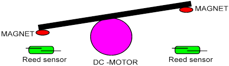
- The oscillation process of the frame is made possible by defining clear bounds for the maximum angle of dip of the frame on either side of the axle of the DC gear motor by using small magnets. At the maximum angle of dip of the frame on either side, the magnets reach sufficiently close to the reed switches to impose a strong magnetic on them. This causes the reed switches to form closed circuits allowing current to flow through them. This change (drop) in resistance offered by the reed switch is recorded by the IC 555 which changes the polarity of DC gear motor. This process can be understood from Block Diagram-1.
- Block Diagram 1
- Changing of the polarity of DC gear motor is established through the H-bridge arrangement. Input of the H-bridge is provided through two opto-coupler circuits which provide optical isolation between IC 555 and H-bridge.
- This is the most important step without which it is difficult to separate out the tracking process from the stopping process(at sun-bright position).
-
4Choosing IC 555
The 555 integrated circuit is an extremely versatile timer that can be used in many different applications. This IC has a monolithic timing circuit that is a highly stable controller capable of producing accurate time delays or oscillations. Additional triggering and resetting terminals are also provided. In the time delay mode of operation, the time is precisely controlled by one external resistor and capacitor. The circuit may be triggered and reset on the falling waveforms and the output structure can source or sink up to 200ma or drive TTL circuits.
The presence of IC 555 in the project allows for oscillation of the reception surface in the absence of a programmed microcontroller. Although the reception surface can no longer be programmed to track the sun, it instead produces oscillations and stops at the sun-bright position. This process of oscillating instead of tracking is not very expensive because the sun undergoes very little displacement in small intervals of time.
Mechanical Solar Tracking Mechanism
The mechanical solar tracking mechanism is a solar tracking mechanism which utilizes only electromechanical means to track sunlight.
Discussions
Become a Hackaday.io Member
Create an account to leave a comment. Already have an account? Log In.