Yann Guidon / YGDES
-
Start/Step/Stop
07/24/2018 at 23:48 • 0 commentsOne simple yet critical circuit is the clock generator.
It must be controlled with the start/step/stop button : it's a SPDT switch with 3 positions, including a middle (no contact) and a temporary position.
So the clock generator must work both in monostable and multivibrator modes...
I already have a 24V electromechanical pulse counter as well as a safe-like rotary knob that generates pulses to help with longer sequences and reduce wear on the SPDT button.
The pulse counter can run at maybe 8 pulses per second, which is 3 times slower than the expected clock frequency. The pulse rate must be limited in this case... a predivider might be necessary.
Initially I wanted to use the mains' frequency (50Hz over here) to "clock" the whole circuit. A dedicated transformer uses a single diode to rectify the 50Hz sine and create 10ms-long half-sine pulses, with 10ms gaps. But 50Hz might be too fast... and it wouldn't be synchronised with external signals (race conditions become possible).
A divide-by-2 circuit is not too hard to make with a few relays. A divide-by-4 predivider is possible too. But apparently this part is more sophisticated than I would think, but I'm not surprised because it was a problem already with the #SPDT16and #YGREC16...
The rotary encoder sends 100 pulses per rotation, and I can use the A or B output at will. It works with 4V/50mA approximately (some spikes/overshoot appears on the output at 5V). I'll try to see if I can gang that output to the pulse counter, through a transistor for example...
Further thinking makes me to ditch the EM pulse counter altogether. It's too slow and will only make things uselessly too complicated.
A much better approach is to use the 5 prototype digits to build the cycle counter, since the predivider is not that hard to build (and can reuse the internal relays) and a 5×4 bits binary ripple counter could be great (ditch decimal !). At least, the counter could work at full speed !
Now, the cycle control unit has :
- One RESET/RUN toggle switch (to clear the state or let the program run)
- 4 push buttons : STOP, STEP, SEQ, START
* STOP just clears a latch that is set by START
* SEQ momentarily shorts the latch's output
* STEP sends only one pulse to nudge the oscillator for one cycle (monostable)
* STEP and SEQ only work when the latch is in STOP state - One rotary button (acts like multiple STEP pulses)
- Pulses are counted and displayed with 5 hex digits => another reset button is required.
it's getting crowded now... so I must split it: the pulse counter is relegated to a separate module, as an "event counter" that can be triggered by other modules, such as the breakpoints.
-
Panel layout
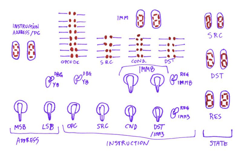
07/21/2018 at 20:02 • 0 commentsI started to sketch the panel's organisation :
![]()
but the right side doesn't look great. Ideally, all the 7 segments modules would be stacked horizontally...
-
Tales of PDPs
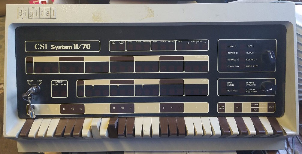
07/19/2018 at 01:25 • 4 commentsDigital's minis in the 70s used a main recipe to design the front panel but there seems to be variations, even inside a given family. The main page shows the PDP8/e, but the PDP11 is interesting too :-)
This is a rebranded PDP11/70 with its red LED dots off :
![]()
(thanks to Thad for the picture ! more on Facebook )
You have to turn a knob or two to display the values you want, in raw binary. The 16-bits field on the bottom could be a register value, or the datapath, the field is unmarked so it's confusing... The 22-bits wide field just above must be a bus address, which again is not directly specified.
Notice that the rotary knob (upper right corner) has 8 positions so it could also encore octal numbers, but they decided to use only one and stick to SPST keys for data/values.
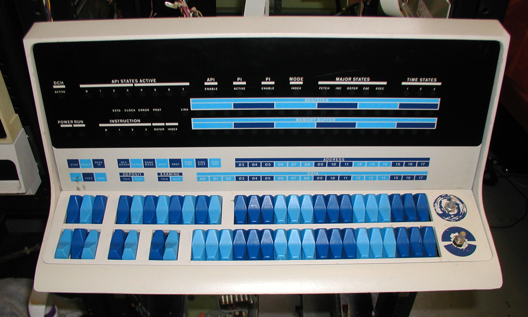
In contrast, the PDP11/20 has a more logical layout because it better matches the processor's structure:
![]()
DEC PDP-11 20 computer at the Computer History Museum (Wikipedia) You have the address, the data, the source, the destination : it seems easier to understand at a glance what's happening.
If only they had used hexadecimal (or octal) displays instead of binary !
Oh wait, it's not LEDs ! According to Wikipedia:
"Another modification made to the PDP-10 by CompuServe engineers was the replacement of the hundreds of incandescent indicator lamps on the KI10 processor cabinet with LED lamp modules. The cost of the conversion was easily offset by the cost savings in electric consumption, the reduction of heat, and the manpower required to replace burned-out lamps. Digital followed this step all over the world."
(OK I know this is about the PDP-10 but they used similar technologies, right ?)
So my idea to use Glühbirnchen is time-accurate :-)
Meanwhile, Digital went berserk with the PDP-15:
![]()
PDP-15 control panel, restored by Mike Ross, 2012 Why did they put the key labels so far from the keys ?...
More front panel stories can be found at http://www.quadibloc.com/comp/panint.htm ! Seriously, click there, it's insane !
![]()
IBM Stretch front panel -
Multiplexing
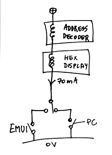
07/17/2018 at 01:06 • 0 commentsIn this log we look at the electrical design of the instruction address bus, which drives the ROM address decoder and the display modules. The address is set by either the PC register, the EMUI switches or an external electronic controller.
The instruction bus has a similar design, except it has 16 bits and is driven by the diode ROM.
The obvious constraint is parts count since relays are not free and they dissipate a lot of power...
So in the beginning, we have the ROM decoder, driven in series with the display module. By design, the #Numitron Hexadecimal display module has a controlled and constant input impedance (one relay coil) that greatly simplifies the series connection. They are tied to the high side, so one only has to tie it to 0V to toggle the bit.
![]()
At 70mA, the relays are well driven, so the + side can be set at about 4V, or more if the decoder needs more coils in series.
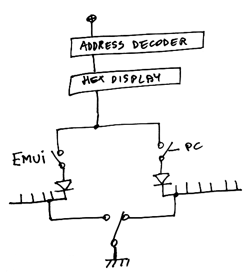
The tricky part is the multiplexing : there is one SPDT switch that selects the source of data, and there are 8 bits to select. That would require an OPDT (Octuple Pole Dual Throw) switch, which, even though I have a few, is far from practical...
It is possible to remove the OPDT with the help of diodes and a single SPDT switch is required :
![]()
This adds about 0.7V to the supply voltage but it saves complexity elsewhere. And without the diodes, there would be shorts here and there...
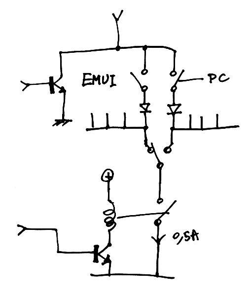
This switch is easily operated by the user. But it doesn't end here ! Now, we want the bus to be taken over by an external computer. A transistor can easily short the "bus" wire to ground but it also must prevent the other current path. This is solved with another relay. That relay must be "normally closed" and must stand at least 0.07×8=0.5A.
![]()
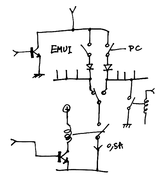
There is still the possibility that the user has left the SPDT switch in the position of the EMUI and that would prevent the external controller from letting the processor run freely... This is solved with the help of yet another relay that short-circuits the PC register rail to 0V, independently from the relay that inhibits the manual SPDT switch.
![]()
There are other possible configurations but there can be no fewer than 2 relays to get the desired functionality, and the system must be functional when the external control circuits are disabled...
Hardware assembler / EMUI
Early computer designers were cheap masochists. This front panel is much better yet could have been made 50 years ago !