Yann Guidon / YGDES
-
Relay-based frequency divider
07/05/2021 at 00:43 • 0 commentsIt took almost 3 years !
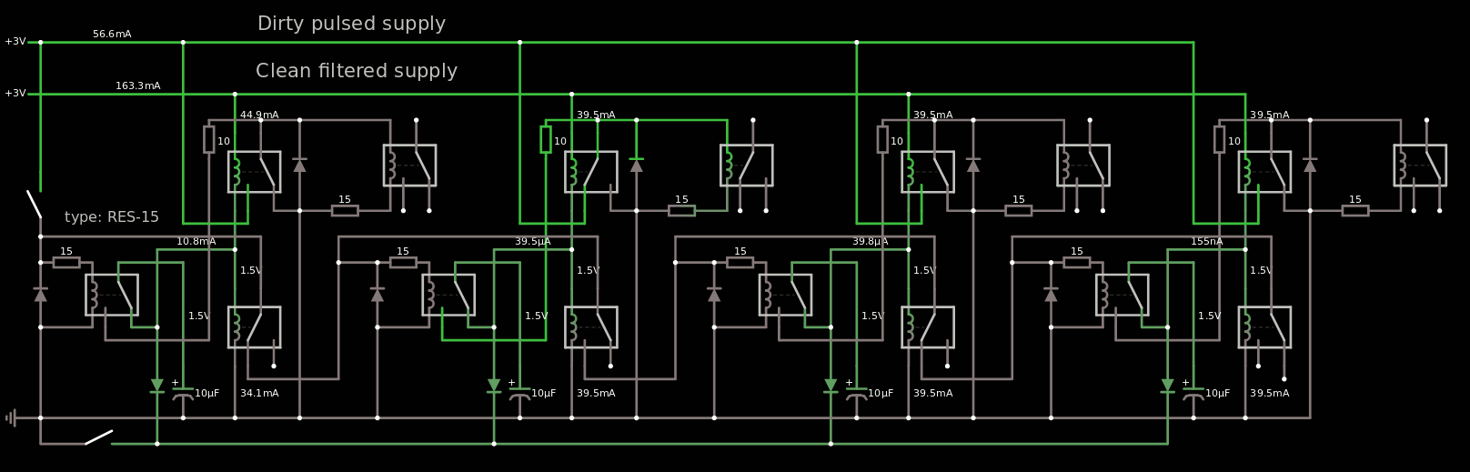
After I researched Log 10. Another relay-based divider... or is it ?, a lot of questions remained and the new version of Falstad's circuitjs with better relay models helped prototype virtually. Here is the result for a 4-stage divider:
![]()
The link is here if you want to play.
You will notice that this is NOT a ripple counter ! All outputs update simultaneously because on the falling edge of the clock input, all the latches are updated, which then routes the clock signals to the appropriate latches to update for the next cycle.
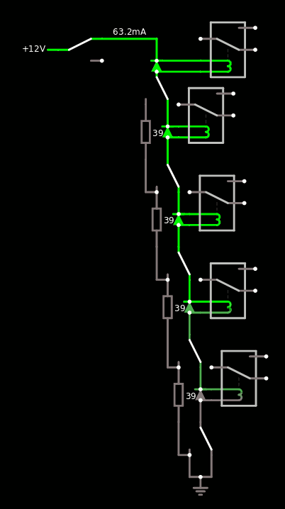
Of course the power demand is too high but there is a solution: connect the coils in series and not in parallel. The circuit will then use 2 power rails: 12V for the series circuit and the "stable/smooth" voltage for the latches (here 2.2V because I fumbled the coils' resistances but that must be tuned in the final circuit).
I have simulated the value of the capacitor down to 10µF though in practice, more headroom will be needed. The anti-rush resistor might also be increased because a low value adds noise to the "smooth rail".
The reset circuit is the usual diode in the center position, pulled to ground with a push button...
The final circuit will use 2 RES-15 per bit, the 3rd one being the input relay of the #Numitron Hexadecimal display module. That's 8 relays per counter board, 40 relays total for the 5 boards.
......
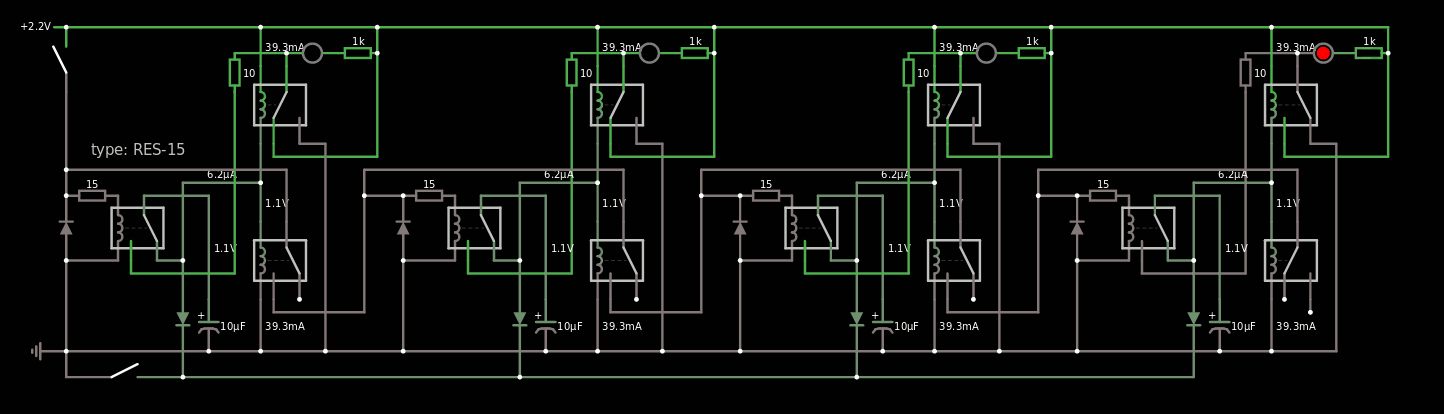
Update 20210708:I was wrong. The display module's coils can't be part of the counting circuit because the associated contacts are used inside the module. The current design does need both SPDT of the hysteretic pair, low-side and high-side. So the display coils must be tied to the high side output, probably. The new version is here: https://tinyurl.com/yjlt5gbn
![]()
That means 3 more relays per bit, and 60 relays for the 20 bits of the whole counter. I must now manage the cascading.
.
Update 20210710:
I added the following serial chain with balancing resistors:
![]()
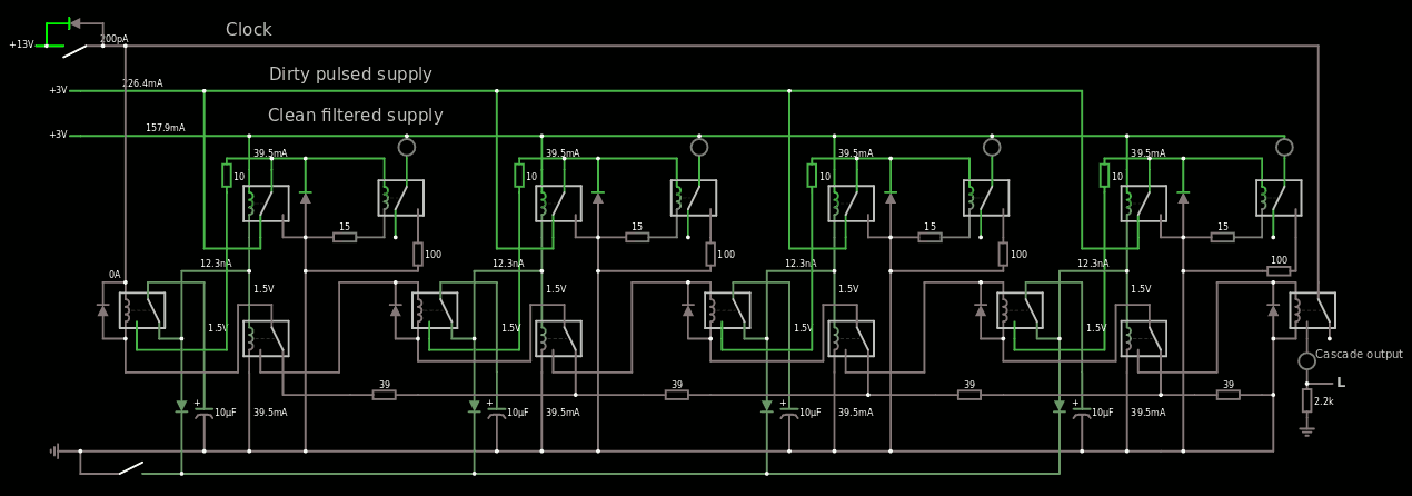
The resulting counter works nicely!
![]()
The resulting circuitjs code is getting pretty long but you gotta do what you gotta do... I hope it works for you: https://tinyurl.com/yer8l4g2
The cascade output restores the clock signal level to drive another identical circuit. There is a little one-relay delay which should not be too handicaping for small chains, but it influences the clock period for sure.
-
The importance of a good programming UI
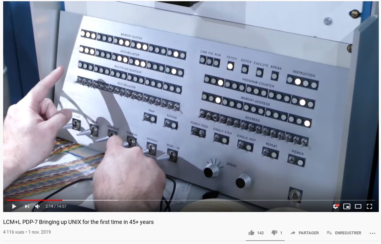
11/17/2019 at 18:31 • 0 commentsCongrats to the team that brought unics v.0 back to life on one of the last working PDP-7s !
![]()
We can see one engineer struggling with all the toggle switches of the front panel... Binary is for the computers !
Why did our predecessors have to suffer these interfaces ?
-
The assembler panel is working !
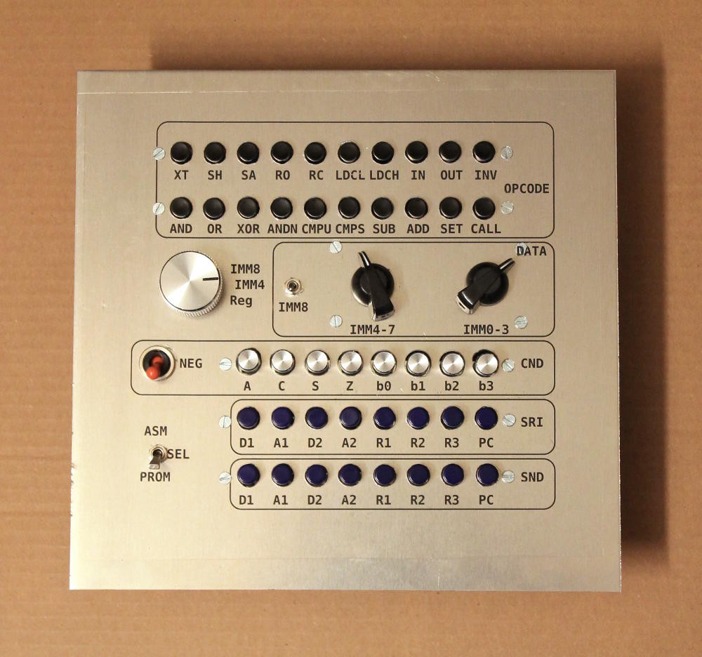
10/13/2019 at 12:01 • 3 commentsIt took a while and many efforts to get every single detail right but here it is !
![]()
The circuit (almost) worked at the first try, I had to swap a few wires and now it is functionally "good" :-D
Some corner cases remain but they are not critical. The panel alone is useless and the user must also look at the disassembler panel to ensure that the buttons send the right signals.
I tested the circuit with a dumb load made of tiny Glühbirnchen but soon they will be augmented with the disassembler panel. I'll have to make a proper panel for the Glühbirnchen because they'll be useful to configure the DIP Switches...
-
Don't go full Numitron ! Unless... OK whatever.
08/06/2019 at 03:29 • 2 commentsThe design of the front panel has evolved lately, as shown in the latest logs of #YGREC8: A new assembler panel. The interlocked switches have brought a new "touch" and "feeling" that beats the original design with only slide switches and rotary encoders.
This "new" increase in user-friendliness makes the disassembler panel's lamps (as planned earlier) look dumb and unwelcoming... What could I do ? Add more Numitrons, of course !
The immediate field is already taken care of with the #Numitron Hexadecimal display module so the rest should be easy, right ? Kinda sortof... But at least I have developed the techniques to make it easier, cheaper and smaller to build.
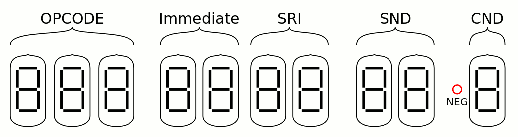
I made sure all the symbols could be represented in 7-segments displays: there are a few exceptions but the majority is unambiguous and explicit.
- The SND and SRI register name fields are identical, they take 3 address bits and 1 enable bit, to represent one of the 8 possible symbols on 2 tubes.
- The CND field is 2 or 3 bits, I squeezed the symbol in 1 tube. The negation is a red lamp.
- The opcode field is 4 or 5 bits and squeezed in 3 tubes.
That's 10 tubes now...
![]()
There are several compromises but it looks much better than the originally planned panel with the many lamps.
I wonder if/how I could share the Immediate and SRI displays. Not to save a pair of Numitrons but to further reduce the clutter...
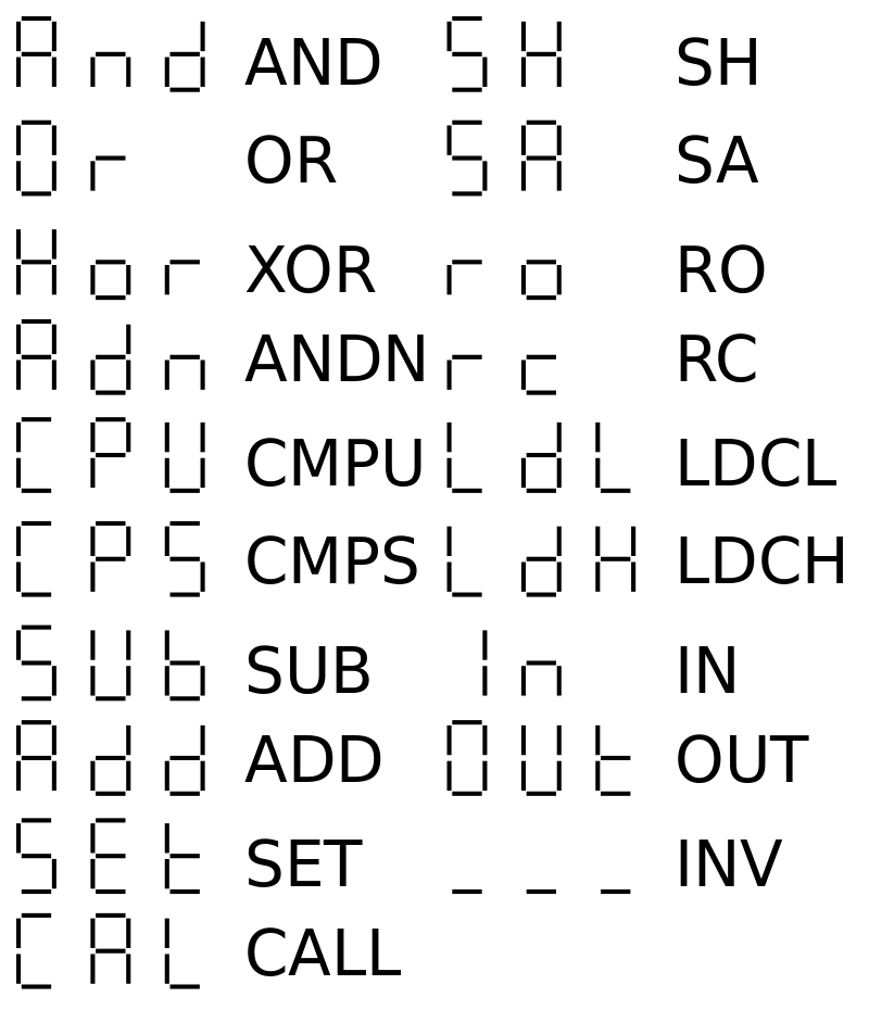
The opcodes look OK with 7 segments and 3 tubes :
![]()
XOR looks strange but I'll live with it.
The register names are easier:
![]()
There are a few obvious tricks to apply, as we'll see later.
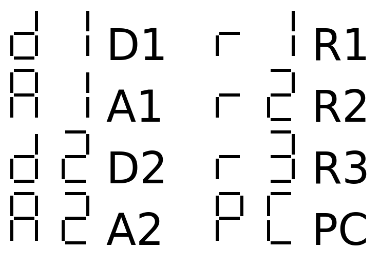
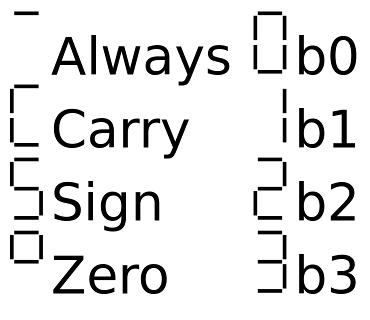
Last but not least : the conditions
![]()
This one is a bit more tricky though because Z can't easily be represented and it would collide with 2. I also didn't want to represent Always as A, it should look inoccuous because it's used most of the time.
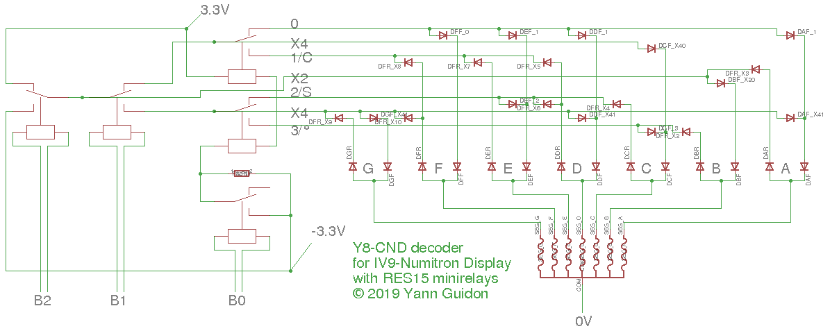
I adapted the design of the #Numitron Hexadecimal display module and reduced the width to 3 bits / 8 codes. It was easy because the 0-1-2-3 codes were already working so I just added the 4 other codes :-)
![]()
There are only 5 relays (including a buffer and BTW I forgot to put a series resistor) but no less then 14+20=34 diodes. It's a single unit so I think the prototype will be OK (and I have already solved all the possible problems). Many diodes are doubled but I can't simplify it because it would break the balance of currents&voltages.
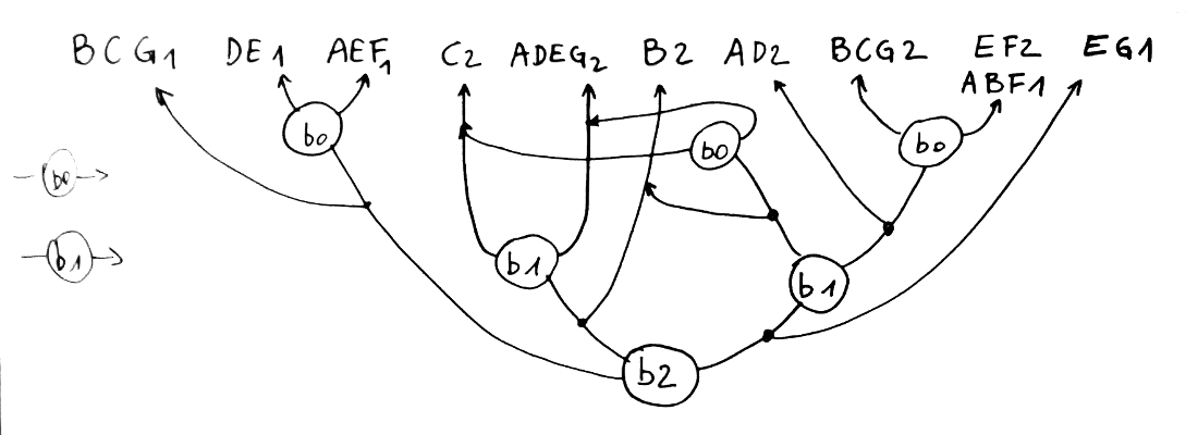
The register names are implemented twice. Each module uses 6 relays (+2 buffers) and 26+14 diodes. I have chosen a unipolar system to simplify things, yet it can be plugged to the existing Numitron tubes, in parallel with the hexadecimal decoder. There is a weird unbalanced binary tree...
![]()
The upper line (the letters) can be a classical array of diodes, and the output can join the anti-feedback diodes of the hexadecimal decoder. But I'm not sure it's relevant to save 2×7=14 diodes anyway... however there must be a way to disable the + and - supply pins of the decoders while the Numitron tubes share the 0V supply.
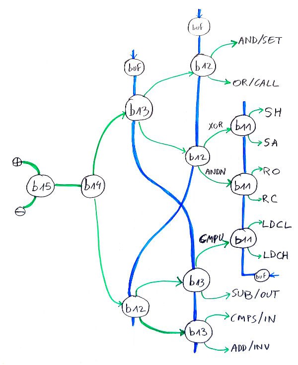
As expected, the opcodes are a bit more messy...![]()
I chose a bipolar design to keep the number of relays low. There is also a fortunate coincidence : there are 3 buffer relays that each drive 3 relays (b11, b12, b13). There is a little crossover with the control lines of b13 and b12 to achieve that, which swaps SUB/OUT with CMPS/IN.
But that's it.
The equations for the segments will be another beast though... I don't know how many diodes will be necessary.
.
-
Another relay-based divider... or is it ?
11/17/2018 at 06:05 • 0 commentsI have been recently tipped that a single-relay divide-by-two circuit existed in the literature.
![]()
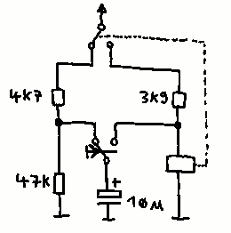
It appears in "Professionelle Schaltungstechnik" Band 4, page 63, from editor Francis Verlag.
I recognize many familiar features and it makes a great use of a DPDT relay. The only main difference is that the relay's SPDT switch can cut the power from its own coil.
![]()
We find the similar-looking current limiting resistor that reduces inrush current in the capacitor, the capacitor that is charged with an alternating voltage, then tied to the relay coil...
I believe that the hysteretic system (where the coil is always half-powered) reduces the energy that is necessary to turn the relay fully on and we can use a smaller, cheaper capacitor. Of course it increases the quiescent power but the working power is halved, and it all reduces to the same consumption in a computer where most bits are 1 half of the time. Hysteresis reduces the power spikes, though, and with the first circuit, they would get pretty intense with a long ripple propagates in a large binary counter...
-
Can I enhance the basic hysteretic latch circuit ?
11/11/2018 at 03:50 • 0 commentsThis hysteretic latch is pretty simple and nice, and I have explored some of its practical characteristics (such as retention time and others) but I always try to improve things.
One welcome improvement is power consumption, and I'd like to reduce the average operating current and voltage. Reducing power also reduces heat-related issues, space, costs, etc. but it can require an increase in the number of parts.
![]()
After all it's hard to do simpler than a relay and a resistor so how can we make the circuit more efficient ?
One proposed idea is to replace the resistor with a diode. I have some germanium diodes that work sufficiently well at these currents (in the 30mA ballpark) so why not try ?
The net effect is to decrease the power supply's voltage by almost 1V because only 0.6V is dropped (instead of 1.6V) and the energy of the capacitor is totally directed to the relay, The capacitor value could then be reduced (or its own power supply). But... it wouldn't work ! Latching would work great but not the release !
To clear the state of the relay, a pulse at 0V is applied to the coil, which is powered by the diode. This forces the diode's electrode to a much lower voltage, or a much higher current (beyond the rated values). It's close to a short circuit from the +3V to 0V through the poor diode that would die young.
A gain in one side is a loss on the other side... Increasing the efficiency of the latch greatly reduces the efficiency of the release. And this little game also happens with other parameters as we dial buttons and add or replace parts.
For example, we see that the release requires a 0V pulse on the coil, and this also draws current from the power supply. So even if we have a diode, we still need the series resistor to limit the current. The ideal circuit would be a current generator but they are not available (a transistor would do it easily but they are ruled out...)
Every deviation from the above circuit creates a new problem or burden, so I will KISS it :-)
For the multi-bits assemblies, the critical parameter will be the voltage across the coil, which must be close to the average of the latch and release voltage. This is what I try to automatically measure with #ReTest-RPi.
-
binary counter/divider with relays
11/10/2018 at 02:28 • 0 commentsOne of the displays of the panel is a counter that uses the 5 prototype #Numitron Hexadecimal display module . The display modules are ready so now comes the part with the counter.
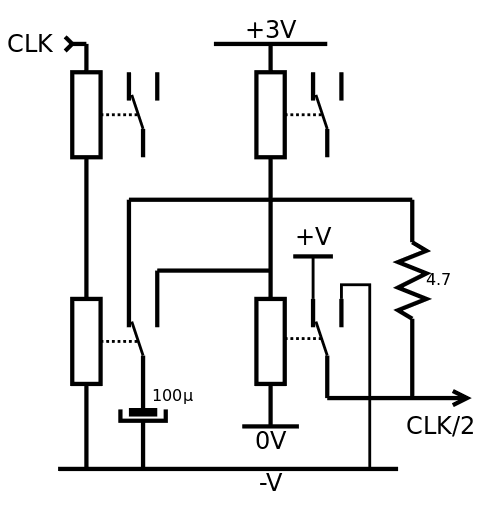
I just made a detailed video about making a divide-by-two bistable, at the heart of a ripple counter (there is no need for something faster because it's just a user panel, unlike the PC display).
The video is light on schematics so here they are !
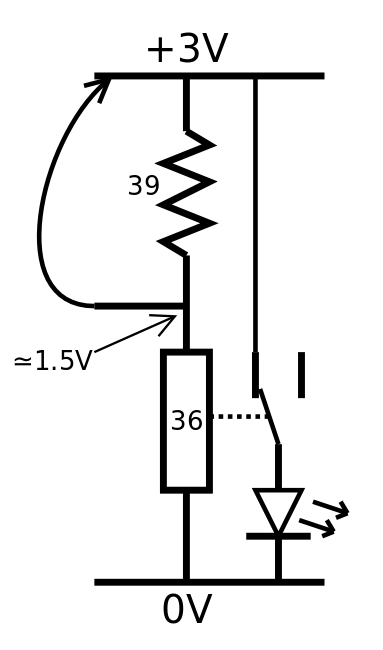
![]()
The first part shows how to work with hysteresis and the RES15 relay. This has been explored for a while now but it had to be repeated again :-)
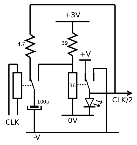
![]()
Then a second relay switches a capacitor between the output and the input of the cell. The charge is transfered through the capacitor to force a spike on the latch's coil. Notice that there are 2 power supplies : one (stable) for the latch relay and its resistor, the other for for the "charge switcher". This is because to save costs and space, the capacitor must be smaller, so a higher voltage difference is required. A small series resistor (here 4.7Ohm) limits the inrush current into the capacitor. A LED shows the state of the latch.
![]()
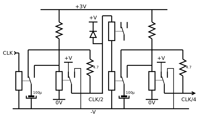
Not shown in the video : these cells can be cascaded because the latch can directly control the coil of the next cell's relay.
The output's range is higher than the latch's power supply so one or two more coils can be conncted in series, to drop the voltage and act as output(s). This series coil can be integrated inside another module, such as the #Numitron Hexadecimal display module (which has 2 wires per input, to make this stunt possible).
Another solution is to replace the 39 ohms resistor with another relay but it might be less reliable. The capacitor would have to fight 2× more inductance and the thermal drift would be higher...
![]()
Now here is a proposed circuit that i'll have to test someday at last :-D
-
25PDT
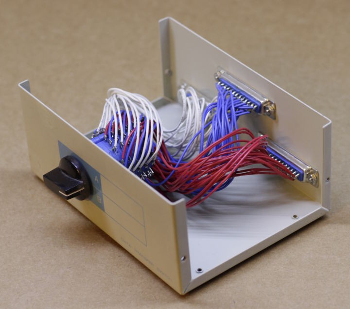
08/16/2018 at 15:45 • 0 commentsThis switch was used to share a printer (or a computer) with its 25-poles dual-throw switch :
![]()
The drawback is its purely mechanical nature. It can't be controlled by another electrical circuit.
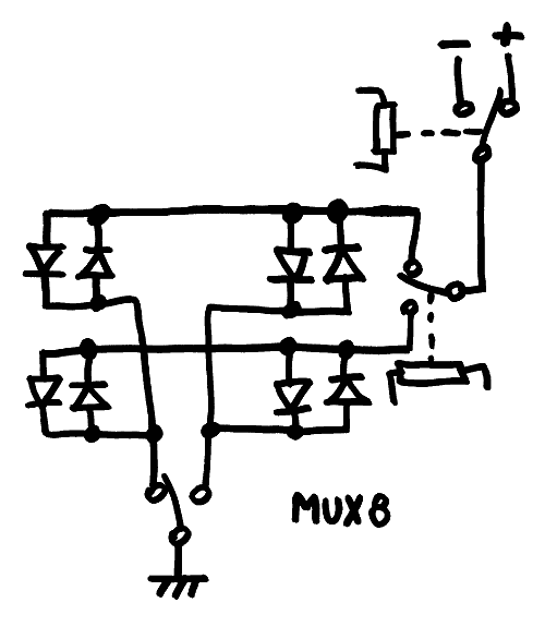
The knob is not too hard to turn but the diodes-based multiplexer is more convenient because an external computer, or another relay, can take over the function.
I wonder how I could use this insane switch anyway...
-
Numitron display modules
08/16/2018 at 01:51 • 0 commentsAfter the success of the 5 prototype units of the #Numitron Hexadecimal display module , the 10 series units have been fabricated. I now have 15 hexadecimal modules :
- The 5 prototypes will be used for an "event counter". It could be a cycle counter, or a condition selected from a set of pulse sources.
- 2 modules for the PC
- 2 modules for the Imm8 section of the instruction
- 2 modules for SRC
- 2 modules for DST
- 2 modules for RES
Unlike the prototype modules, the new modules have their IV-9 soldered with the full length of the wires preserved, so they can be resoldered to fit a useful mechanical layout. I had to solder them anyway so the whole could be tested.
I'm pretty satisfied with the results, and now I have to build the other decoders for the remaining fields of the instruction word. I'll start with the @SRC, the COND and the @DST fields that are 3 bits wide each. The circuit has been covered already.
![]()
I must also work on the binary counter but I have no idea which project it belongs to. Probably here ?
-
The dawn of the micros
07/25/2018 at 11:00 • 3 commentsFrom https://twobithistory.org/2018/07/22/dawn-of-the-microcomputer.html:
"
Popular Electronics had in fact been running a series written by Roberts for several issues before January 1975. The series was billed as a short course in “digital logic.” In the December 1974 issue, Roberts walked readers through building a “very low cost computer terminal,” which was basically an octal keypad that could input values into an 8-bit computer. In the course of describing the keypad, Roberts explained how transistor-to-transistor logic works and also how to construct a flip-flop, a kind of circuit capable of “remembering” digital values. The keypad, Roberts promised, could be used with the Altair computer, to be announced the following month.
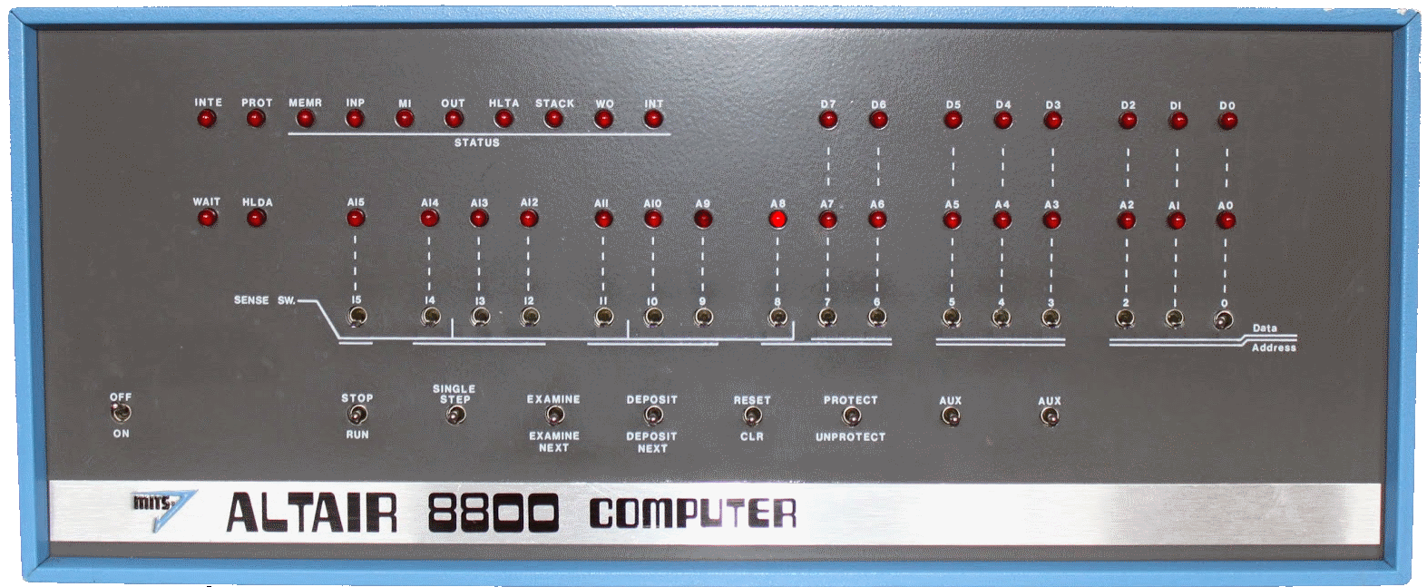
It’s unclear how many Popular Electronics readers actually built the keypad, but it would have been a very useful thing to have. Without a keypad or some other input mechanism, the only way to input values into the Altair was through the switches on the front panel. The front panel had a row of 16 switches that could be used to set an address and a lower row of eight switches that could be used to control the operation of the computer. The eight right-most switches in the row of 16 could also be used to specify a value to be stored in memory. This made sense because the Intel 8080 used 16-bit values to address 8-bit words. The 16 switches on the front panel each represented a bit—the up position represented a one, while the down position represented a zero. Interacting with a computer this way is a revelation (more on that in a minute), because the Altair’s front panel is a true binary interface. It’s as close as you can get to the bare metal.
As alien as the Altair’s interface is to us today, it was not unusual for its time. The PDP-8, for example, had a similar binary input mechanism on its front panel, though the PDP-8’s switches were nicer and colored in that attractive orange and yellow color scheme that really ought to make a comeback. The PDP-8, however, was often paired with a paper-tape reader or a teletype machine, which made program entry much easier. These I/O devices were expensive, meaning that most Altair users in the early days were stuck with the front panel. As you might imagine, entering long programs via the switches was a chore. Eventually the Altair could be hooked up to a cassette recorder and programs could be loaded that way.
"
![]()
Though clicking on switches does not offer the same tactile satisfaction as flipping real switches, playing with the Altair simulation is a great way to appreciate how a binary human/computer interface was both horribly inefficient and, at least in my opinion, charmingly straightforward.
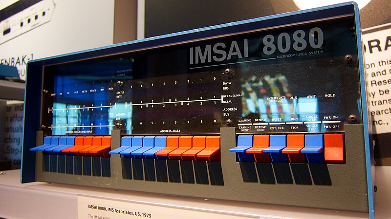
![]()
IMSAI 8080 computer at the Computer History Museum No wonder I focus on the UI and not just the processor...
Hardware assembler / EMUI
Early computer designers were cheap masochists. This front panel is much better yet could have been made 50 years ago !