MasterOfNull
-
Parts making cutouts.
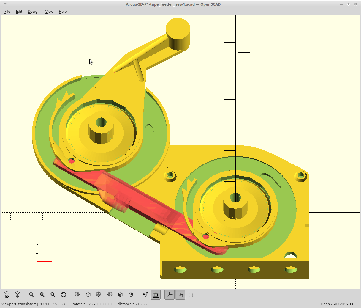
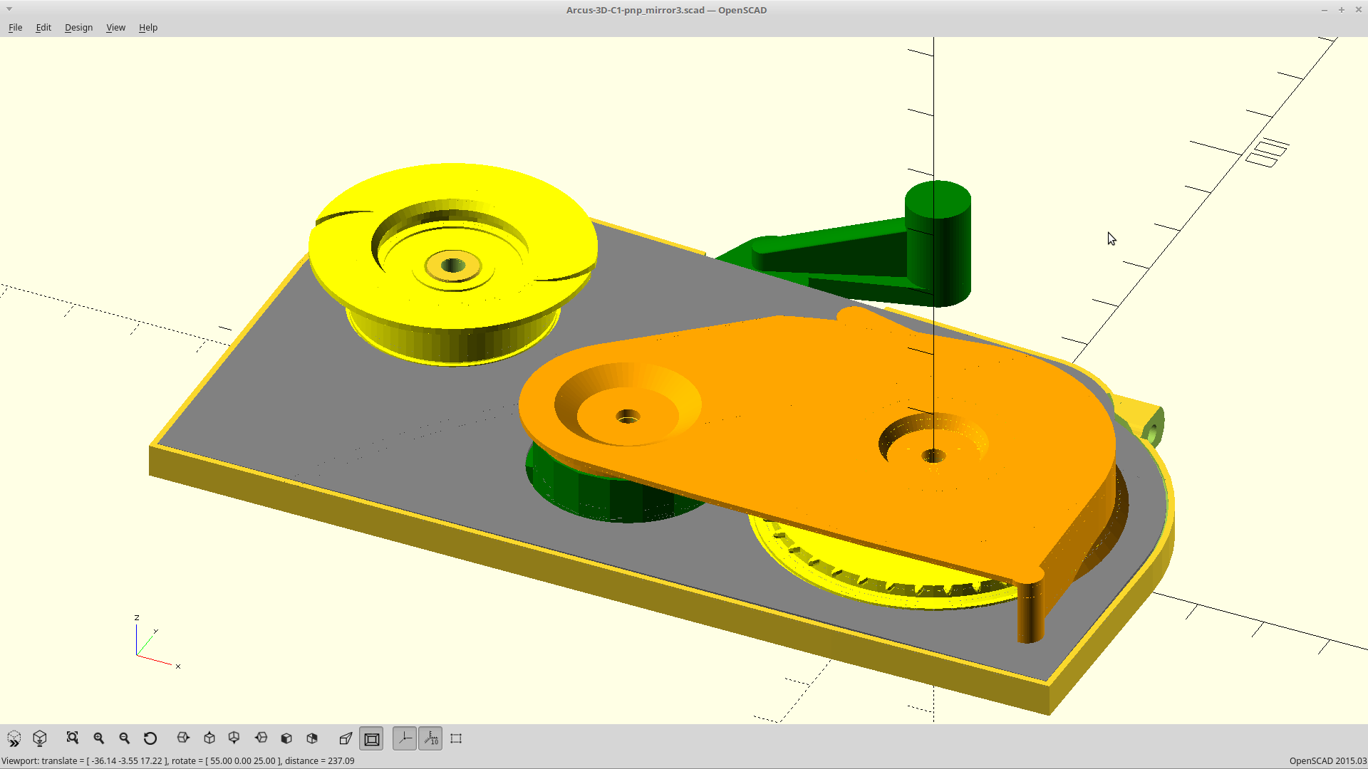
07/27/2018 at 01:43 • 0 commentsI usually try to shy away from using parts to make their own cutouts in OpenSCAD. However after 2 hours of trying to find the right math to duplicate the motion, once I found it, I used it.
![]()
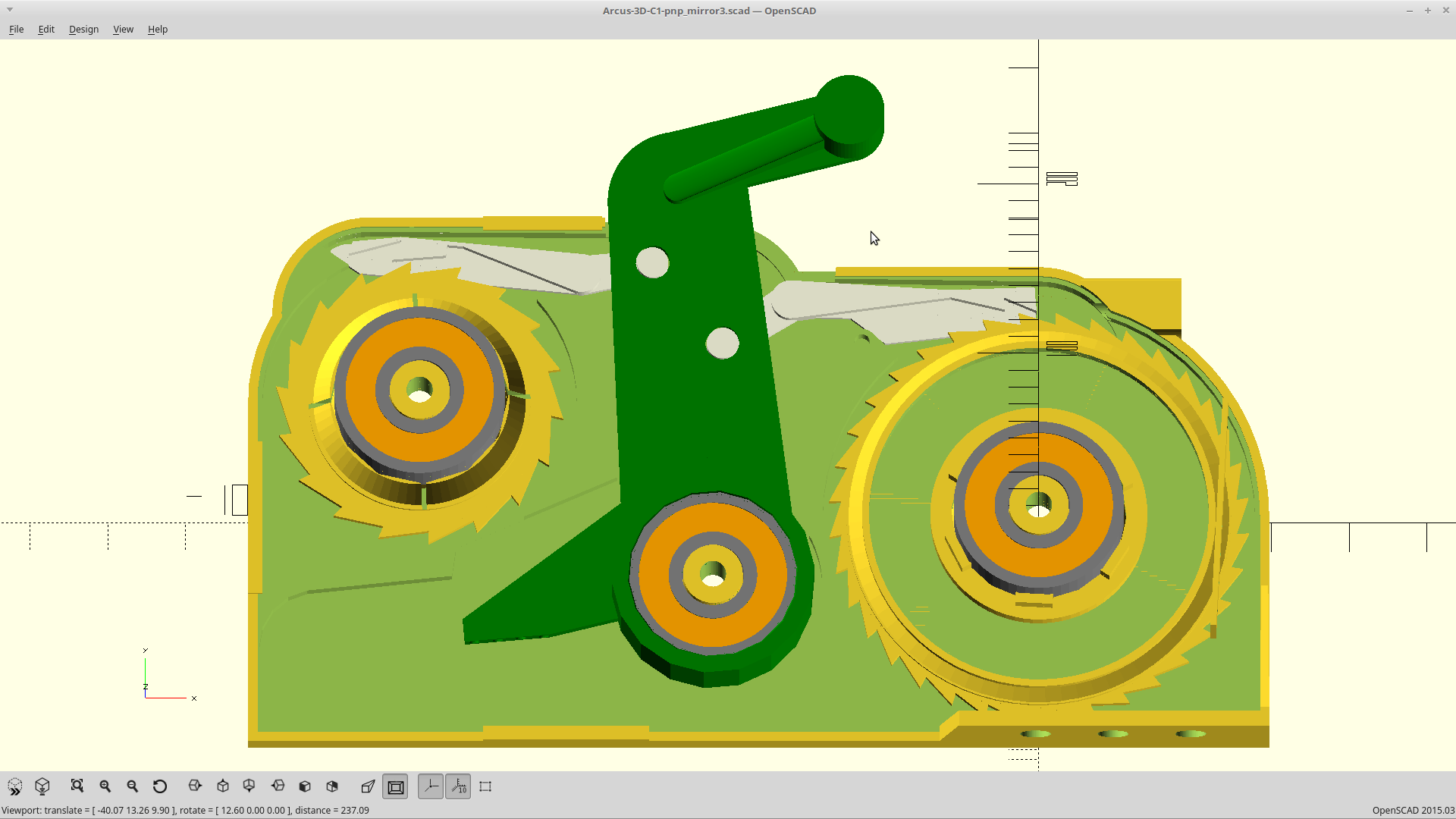
The red area is the lever arm part which joins the two ratchets, cutting away at the base plate.
I toyed with using a living hinge to join the two ratchets for a long time, but they can only pull reliably, not push.. and pulling put it crossing the tape path right at the entry point. I scrapped it.
Also finished the mounting posts for the part cover and cleaned up/added some comments to the code. I think I'm finally ready to print again!
-
Cover slip support work.
07/26/2018 at 21:58 • 0 commentsHad this idea for printing the cover slip flat, and then bending it into place.
![]()
The cover would sit in the slots here.
Problem with this is I removed the ability to disengage the ratchets as it was getting too complicated. This means you can't get the tape back out as there isn't enough clearance between the posts and the tape thickness, and besides.. you would have to go out the side to do it.
New idea... use posts raised up some more, and snap the cover under it. The ends of the slip would be raised then to meet the post instead. I'm going with that.
-
Buddha belly.
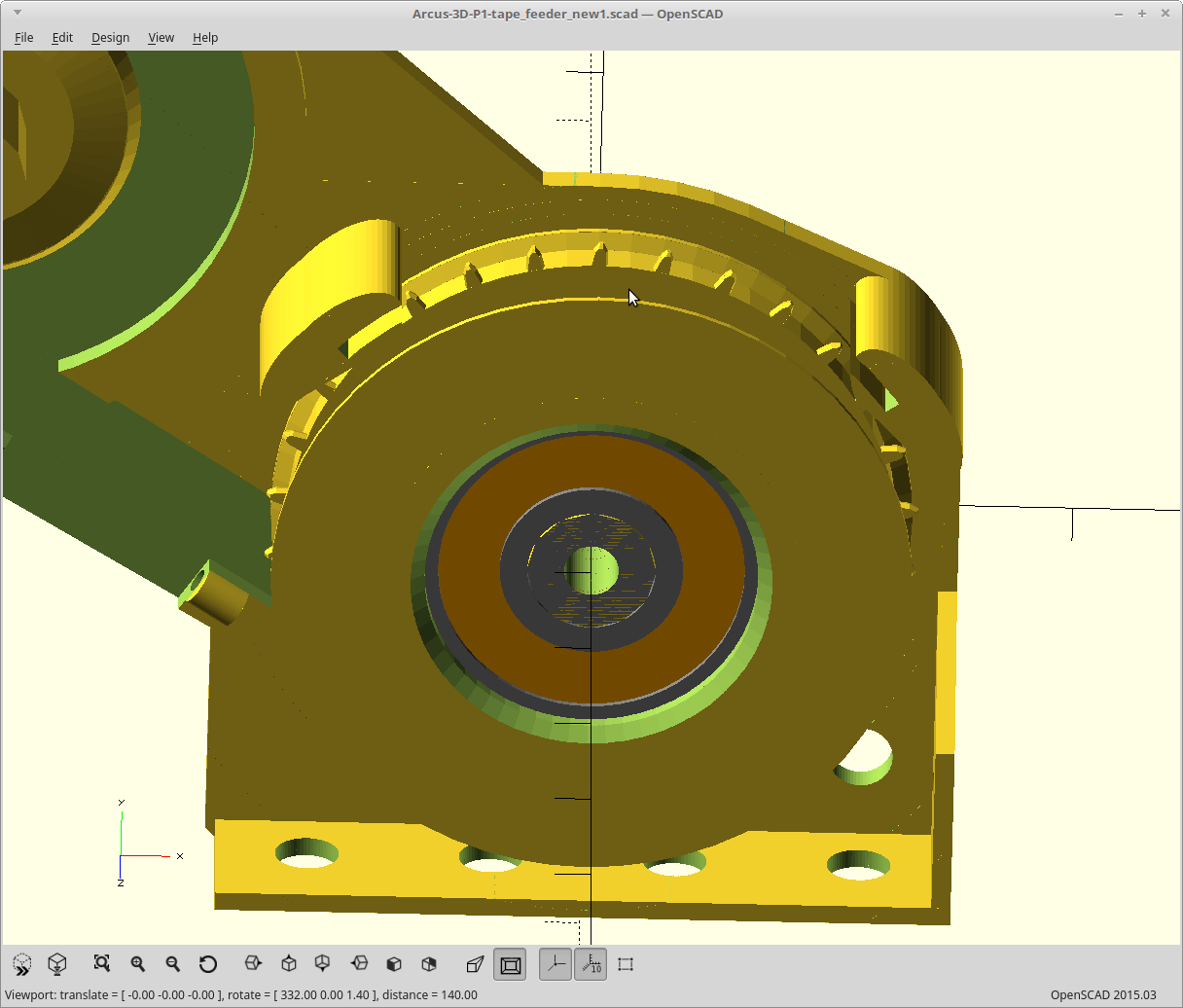
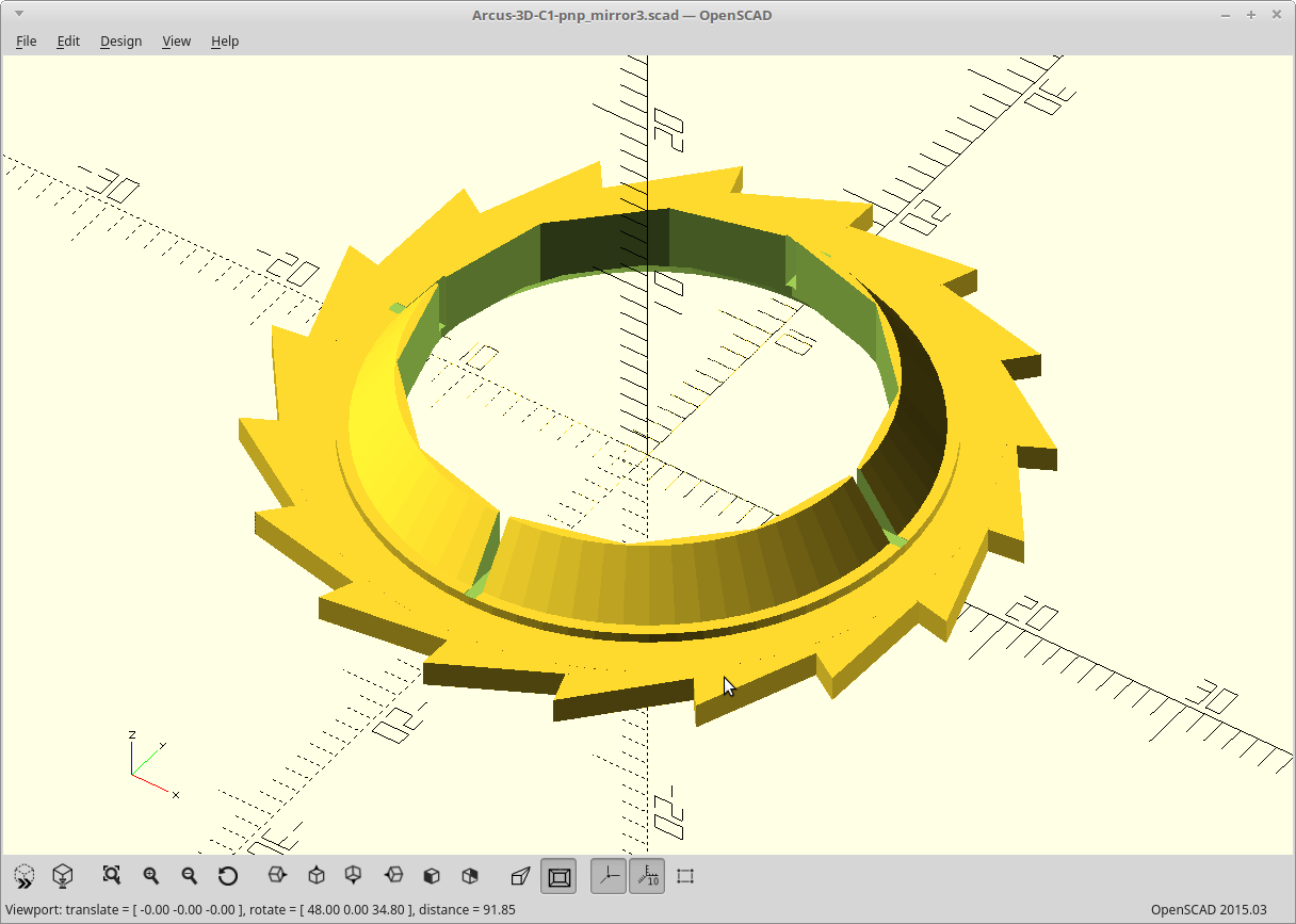
07/26/2018 at 14:57 • 0 commentsI was able to squeeze another 1/2mm of thickness off the design by making the drive wheel and cover tape wheel turn at equal rates. I made up for this by making the cover tape reel slightly larger than the drive wheel (so the clutch still slips). Its got a Buddha belly now.
![]()
11.5mm of width is just .5mm more than the reel the 8mm tapes come on. I'm done making it thinner.
I have a new idea for how to handle the cover slip the components show through. I think you're gonna like it.
-
Reality.
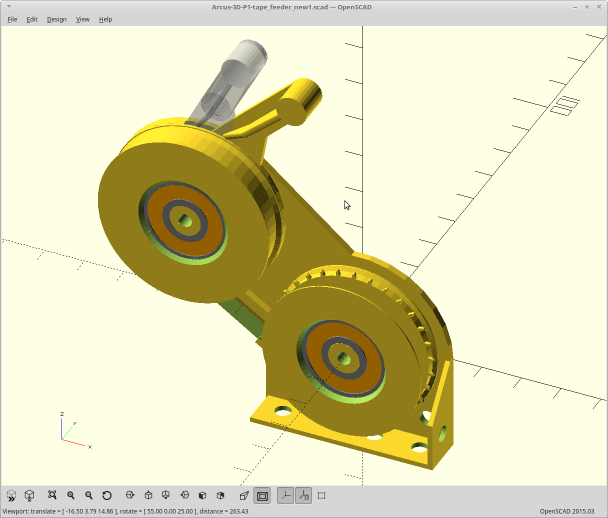
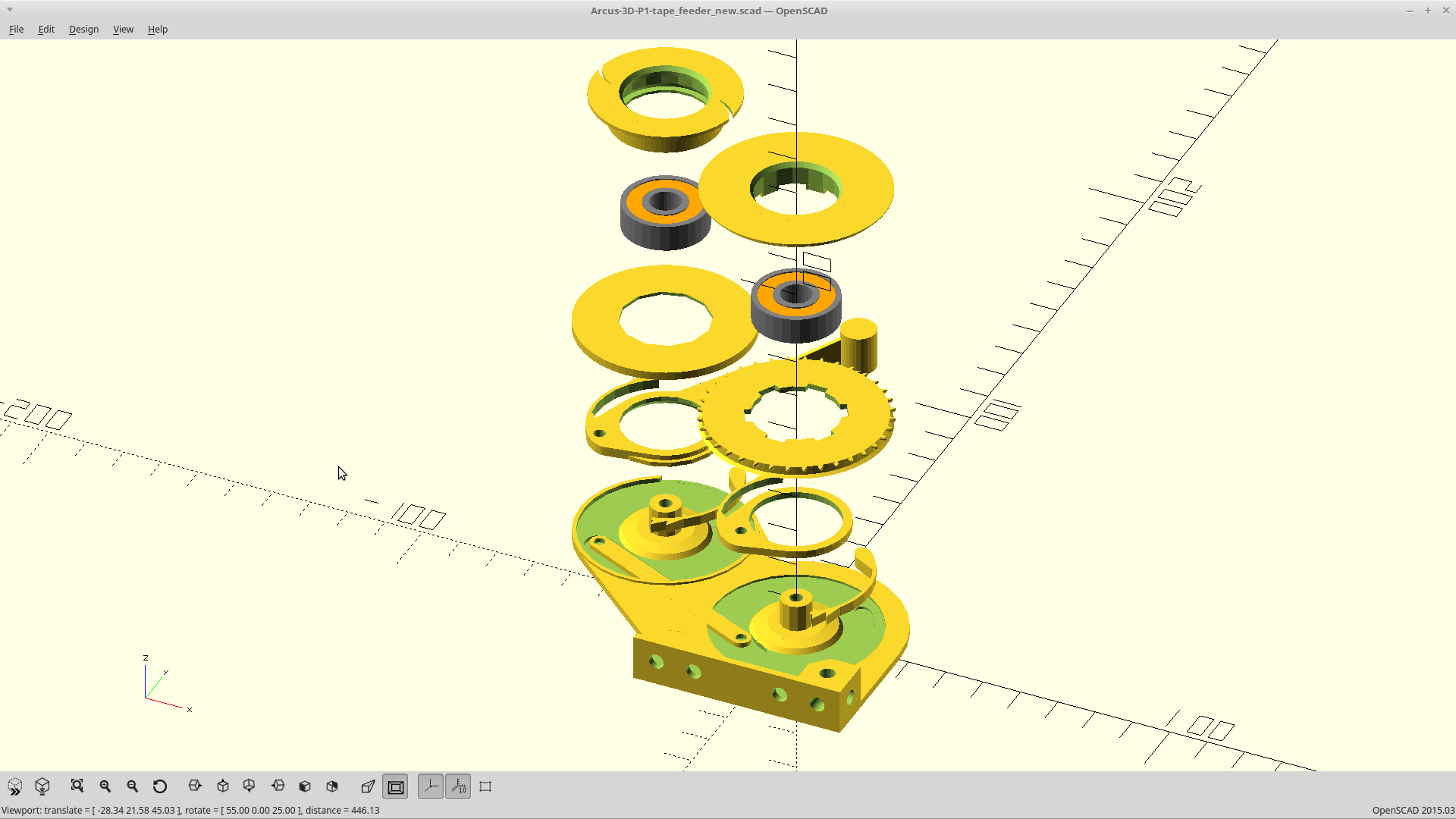
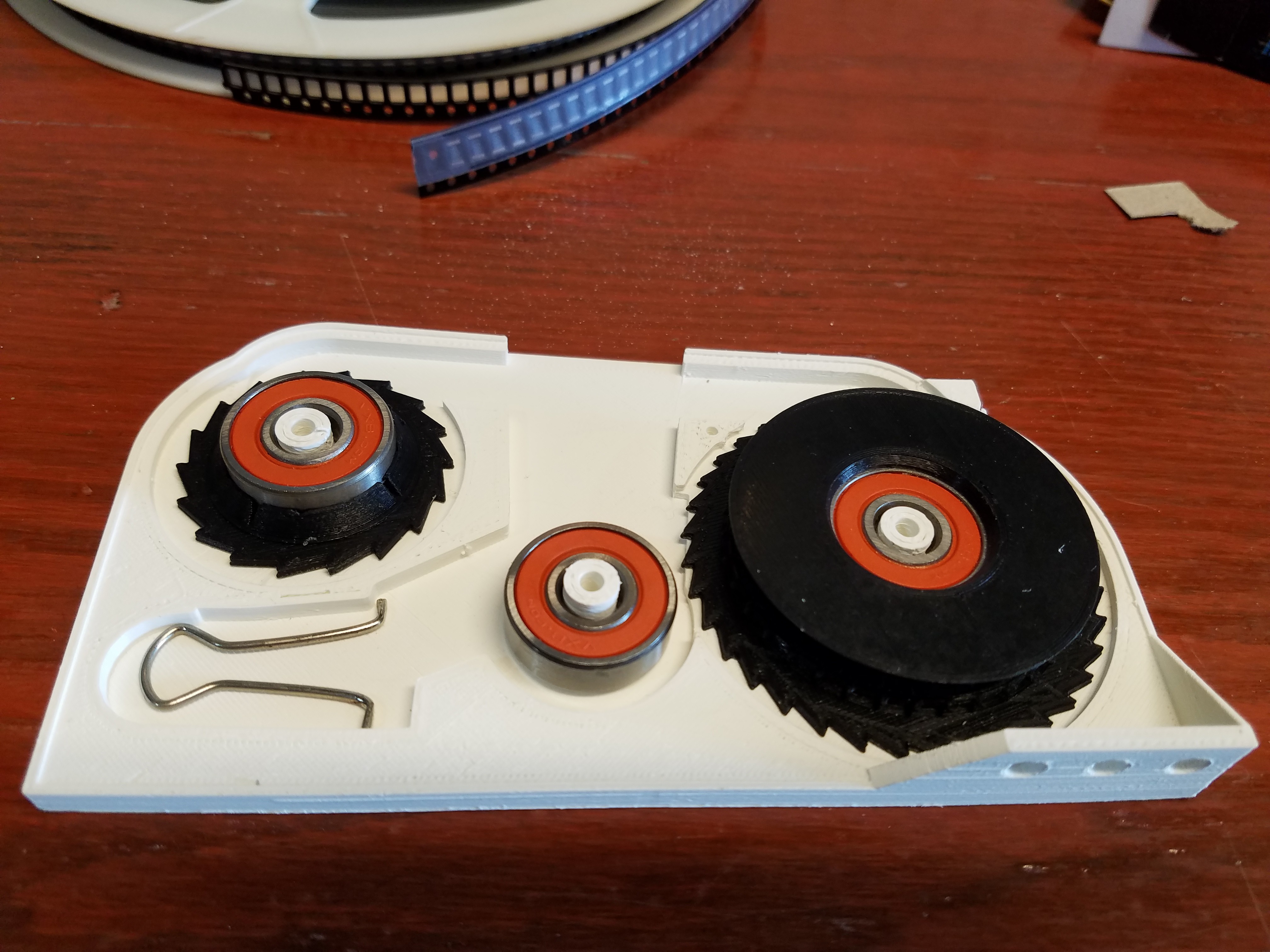
07/25/2018 at 04:30 • 0 commentsAnd here it is, minus the cover.
![]()
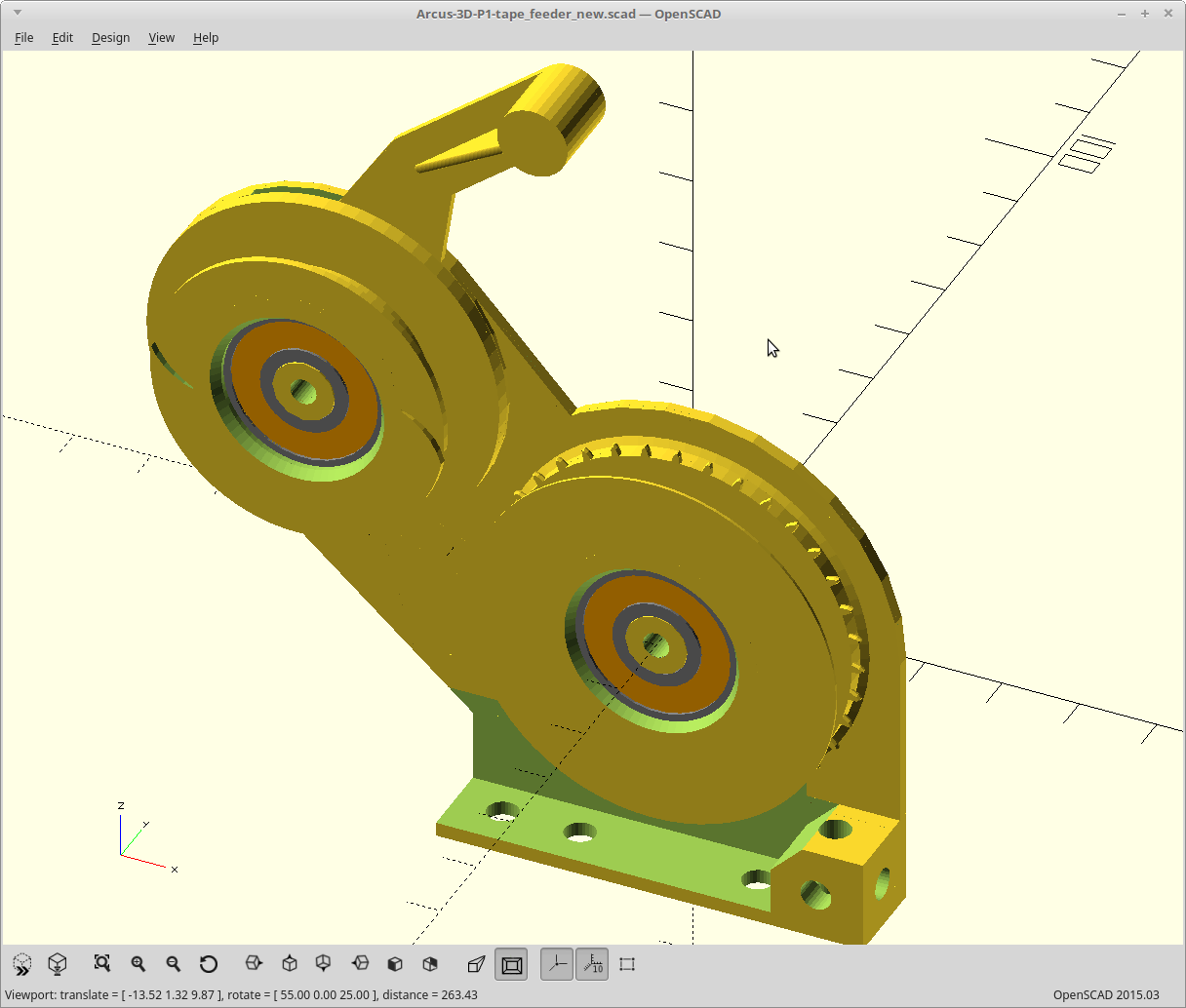
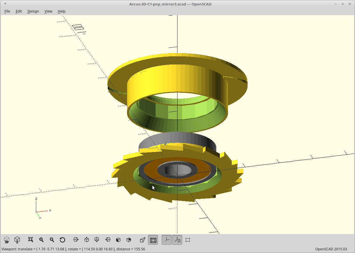
Exploded
![]()
- Came in at <tape width> + 4mm.
- Drives the tape with a sprocket, on the release stroke of the feed lever.
- Supports the tape up against the cover window from both edges, and centers it.
- Removes the cover tape and has an integral slipper clutch that you can adjust the tension of.
- Supports tapes up to 8mm depth with no adjustments. Supports tapes up to 24mm wide by changing 2 parts, which are parameterized. Tapes with feed holes on both edges are supported.
- All cams and ratchets are spring loaded and positive acting (force on them engages them more).
- Travel stop is adjustable.
- For hardware, it requires 2 skateboard bearings, 4 M3 bolts, 2 M3 nuts, one O-ring, and a binder clip.
And.. It will all print flat with no overhangs, minus the connecting rod cutout. I may just make that a through.
I'm so happy with this I can hardly stand it.
-
The subconscious is a wonderful playground.
07/24/2018 at 10:16 • 0 commentsAn idea for a coaxial drive mechanism has been bouncing around my head since I started this, but I could never quite make it work.
I just dreamed of how I could 3D print it without overhangs, without using two bearings, and without wasted material or space.
So... that design just took over this project for now as I see if I can literally turn my dreams into reality.
-
Binder clips are surprisingly strong..
07/24/2018 at 02:54 • 0 commentsI added the binder clip in. Well, combining the thinner parts with how strong the binder clip is flexes the shell now.
I modeled 4 different spring tensions into the lever arm and base plate as 8 sets of holes. The closer you get to the pivot, the less applied force. All of them are way too strong.
So, I need to change that, beef things back up a bit, and still stay thin or at least stay out of the tape path.
Secondly, my choice of using gravity to engage the ratchet arms is not reliable. The attachment to the lever arm as modeled is a pin, which grabs in the socket on the arm. It would probably work fine if it weighed more than a gram, but it doesn't.
It all amounts to it only works... sometimes.
The way I see it I have two choices for the ratchets. Add an actual spring of some sort, or model a 3D printed spring and build the lever arm and ratchets as one piece. I toyed with the latter already and it works, but accuracy is not as good.
Working on it.
-
Well Duh..
07/23/2018 at 13:08 • 0 commentsI had to fix some things.
After I printed it all and assembled it, I realized that I didn't make a way for you to unload the tape without disassembling it. Duh...
Now if you push the lever arm all the way back (2 degrees past where the normal stop is) it disengages both cams.
![]()
It also turns out 15mm is not a standard length for 3mm bolts. This meant that I had to choose between 14mm and 18mm. Well.. that sucks. I'm not making the whole thing thicker for a bolt, and I'm not cutting them all either.
I also compared my upper profile to a Juki nozzle and discovered I didn't have enough clearance. I'm not using an off the shelf nozzle, but I should probably plan for that.
So.. I reworked the entire design to be 1.5mm thinner so I can use the 14mm bolts, and I lowered the front cam area to clear the nozzles. While I was at it I added some tabs to retain the cover more nicely.
I'm happy. Printing again.
-
Printing..
07/22/2018 at 19:51 • 0 commentsBase plate is finished. A little too much clearance on the bearing posts, but probably won't matter. Notice the addition of my favorite piece of hardware a binder clip as the spring for the lever return.
![]()
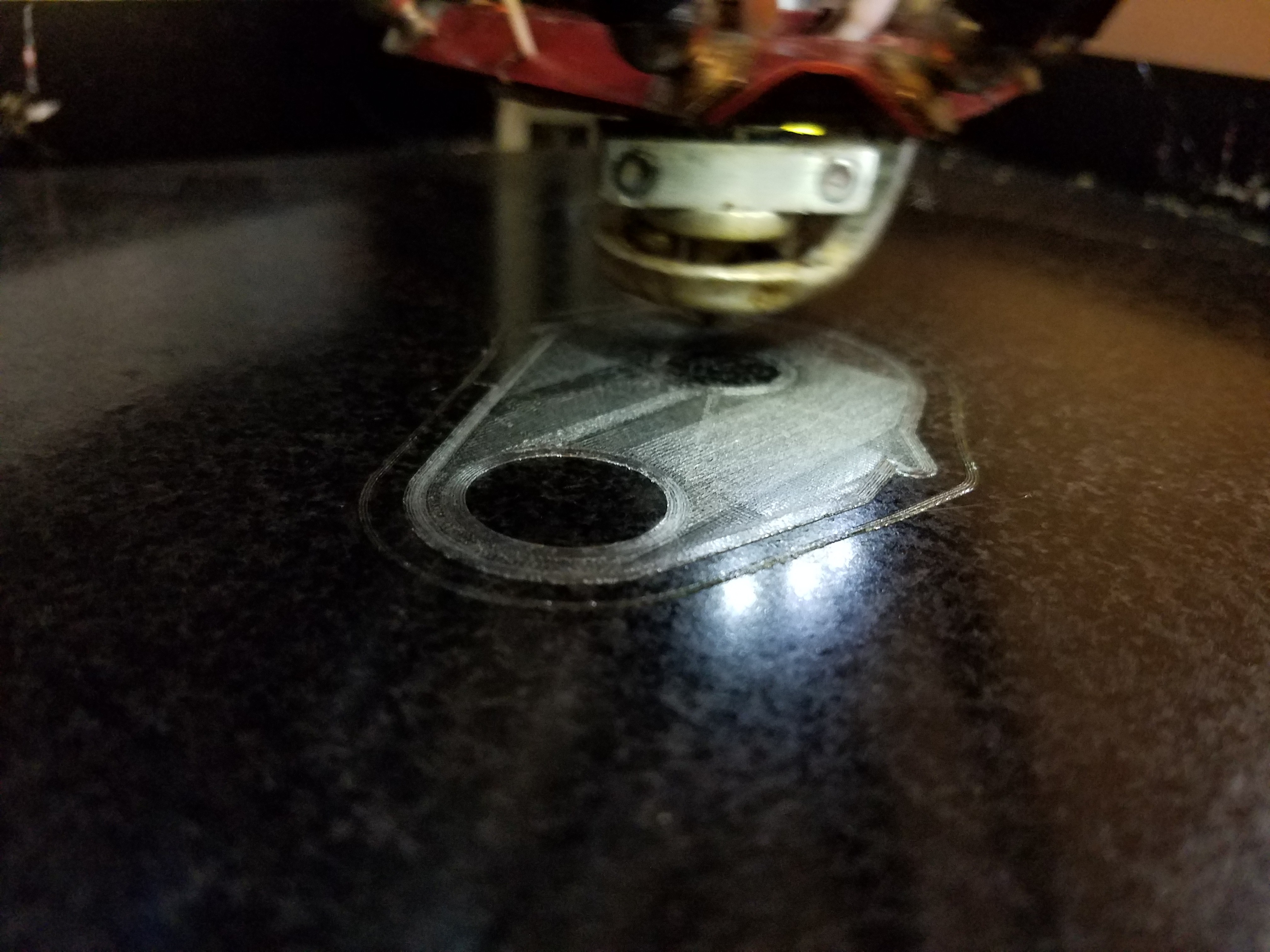
Printing the spool cover in 'clear' Should look nice if I can remember how to properly print in clear.
![]()
-
Done?
07/22/2018 at 02:26 • 0 commentsAssuming I didn't screw up anywhere, it's done.
![]()
Final dimensions are <tape width + 7mm>, so for 8mm tape it takes up 15mm and for 16mm tape it takes up 23mm.
I can go another 2mm narrower, but it will start to sacrifice some strength for my ratchets so I'm starting here.
This is going to take a while to print..
EDIT: Oh... I suppose I should provide some way to actually mount this thing. Not quite done it seems..
-
Slide.
07/21/2018 at 01:46 • 0 commentsWhile I was working on generating the cover/tape guide, I was printing out the cover tape feed sprocket.
Getting just the right tension was proving challenging, so I changed the design.
![]()
The addition of the slots should allow those areas to bend out slightly. The mating slant from the upper portion now means that downward pressure will increase the tension.
This should now allow me to tune the friction. Now I can put a thumb screw or the like in the center on the bearing, and ultimately control the applied tape tension that way.
![]()
There is one caveat in that the feed sprocket for the cover tape will now slide against the body to maintain that tension, so I will have to make sure that source of friction is less than that which the bearing surface is presenting. I think adding a few raised areas on the body will suffice.
Back to work..
P1 - Buddha Tape feeder
3D printable Pick and Place tape feeder for the Arcus-3D-P1.