stupid
-
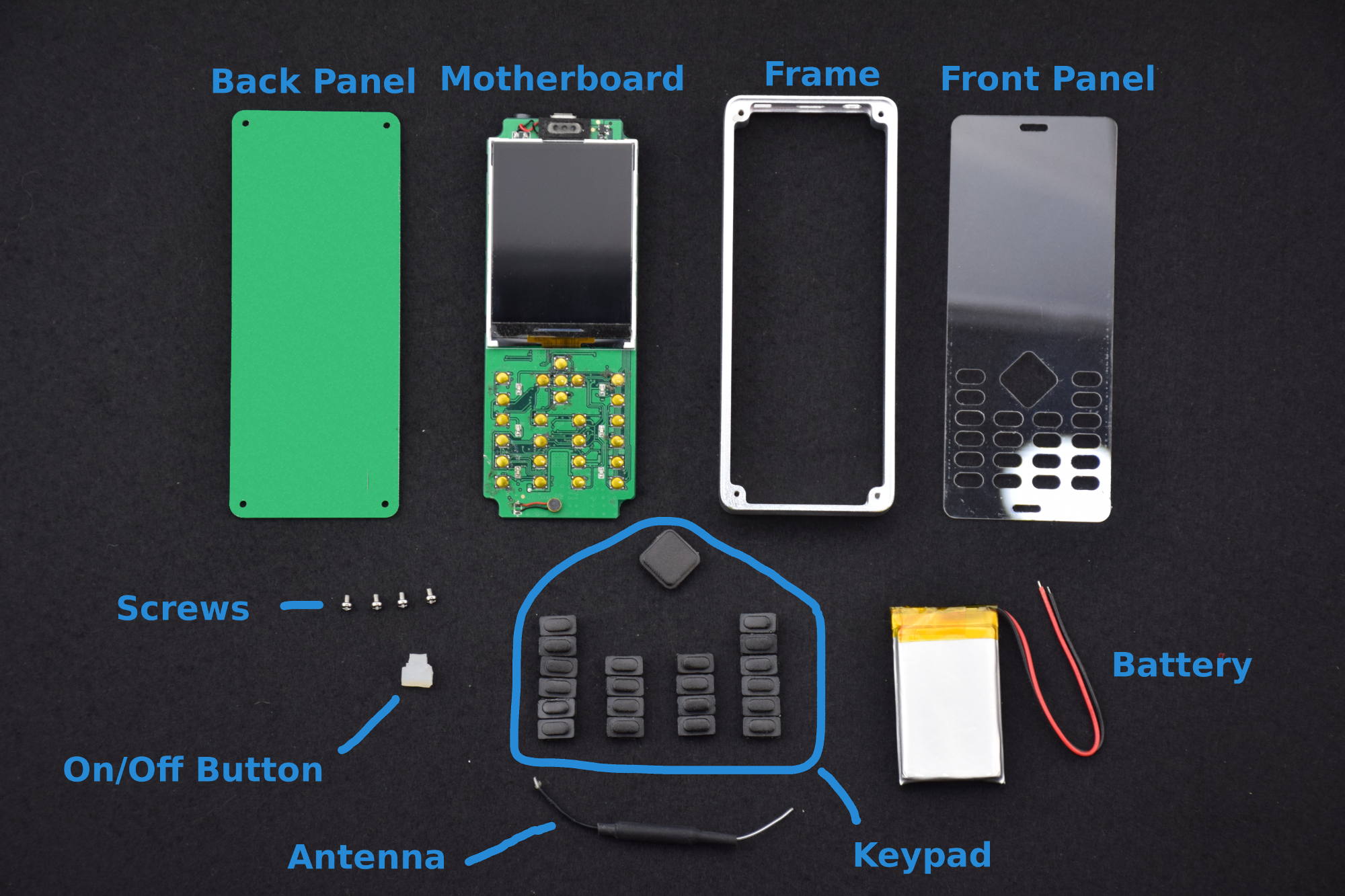
All Components Are Here
09/07/2018 at 09:26 • 0 commentsWe have all the components on hand now.
![WiPhone Components]()
WiPhone Components Parts List:
Back Panel - FR4, cut to the correct profile
Motherboard - 4 layers, hand assembled
Frame - Aluminum, CNC cut and clear anodized
Front Panel - 2mm thick polycarbonate, CNC cut
Screws - M2x4, 4x
ON/OFF Button - Silicone, artisinal hand carved (OK, actually hand-snipped with a pair if dikes)
Antenna - Whip antenna, we may change to chip or trace antenna after we do some signal strength optimization
Keypad - Hard plastic, CNC cut. Eventually this will likely be a single cast silicone part.
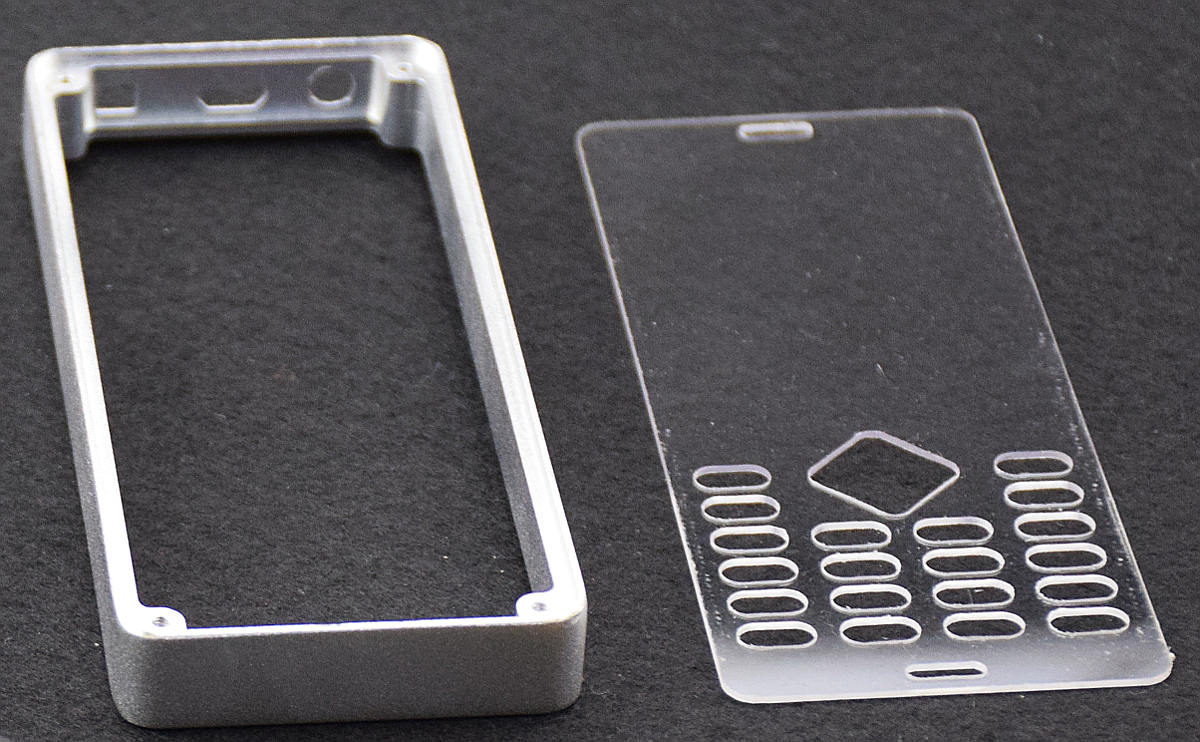
Battery - LiPo pouch.As the perceptive among you may have noticed, the parts have been assembled and our project pic updated. Later we will post more info, but for now we can say that everything fits with only minor issues. And the overall build looks and feels great, especially given how few revisions there have been.
![Shell]()
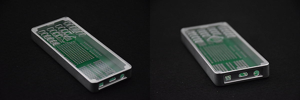
![Shell, Partially Assembled]()
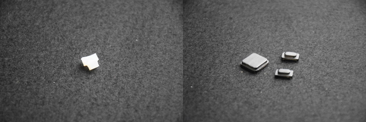
![Buttons]()
-
GUI Screenshots
08/18/2018 at 01:16 • 3 commentsSome shots of the current state of the user interface. Implemented so far:
- make a call
- receive a call
- address book
- wifi scanning
- wifi credentials management
- SIP account management
- boot screen
![]()
- make a call
-
Populated Motherboard
08/17/2018 at 01:30 • 0 commentsNow with wires and little square things all over it:
![Populated WiPhone Motherboard]()
Populated WiPhone Motherboard -
LCD Graphics Driver Benchmarking and the Facts of Life
08/16/2018 at 00:42 • 1 commentWe recognize a few universal truths: Biological life… errr… finds a way. Every software program expands until it can check email, or dies trying. All online discussions of sufficient length end in references to Nazis and utter disdain for opposing viewpoints. And all screen-bearing hardware evolves to kill bad guys at the maximum screen rate possible. So, bowing to the evolutionary pressures that are the natural order of things, we’ve started benchmarking and optimizing our graphics performance. Also, we were really tired of debugging hardware and wanted a fun break for a bit.
Background
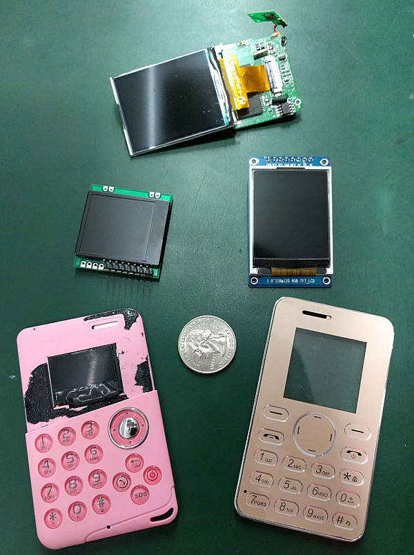
Originally we were thinking to put a much smaller TFT display in the WiPhone. Something like 1.4" or 1.8" display. These screens are usually driven by an ST7735 driver over SPI.
![Small Screens]()
Small Screens Trouble is, nobody likes phones with tiny screens like that. They’re ugly. And killing bad guys on a tiny screen is unsatisfying. Luckily, we quickly abandoned the smaller screens and switched to a 2.4 inch screen with 320×240 pixels. But the ESP32 isn’t blessed with an abundance of extra I/O, so we are stuck with the lower bandwidth SPI bus now needing to push roughly 4x the original data out to the screen.
As you can see in our first demo video, the graphics library that came as example code with our screen was struggling to refresh even a basic phone interface. Each widget is noticeably re-drawn.
Most phones with a screen this size use a parallel 8-bit bus (a.k.a. “8080 series MCU interface”). But given the limited pins on the ESP32 and all the other things a phone needs to do, something needed to give.
Benchmarking
Luckily, we found a beautiful and fast library called TFT_eSPI by Github user Bodmer, which is optimized for ESP32 chips. Our ST7789 driver IC was not yet supported, but an initialization routine and a pull request later we were pleasantly surprised by a 3-12x speedup!
Here we run Xark’s benchmark with our bigger screen using TFT_eSPI library, as well as the original library we developed:
NVIDIA, eat your heart out.
-
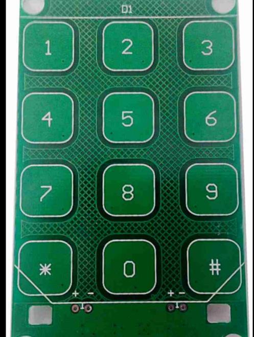
SN7326 Keypad
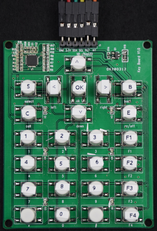
08/15/2018 at 12:52 • 0 commentsThis is a simple keypad to test the SN7326 I2C keypad controller in the 25 button configuration we wanted for the WiPhone. Posting in the hopes it might be useful to someone else.
Hosted on Gitlab: SN7326 25 Button Breakout
Overview (from the SN7326 datasheet)
The SN7326 is a 64 key, key-scan controller. It offloads the burden of keyboard scanning from the host processor.
The SN7326 supports keypad matrix of up to 8×8. Key press and release events are encoded into a byte format and loaded into a key event register for retrieval by the host processor. The SN7326 integrates a debounce function which rejects false or transient key switch activities.
The interrupt output (INT) is used to signify if there are any keypad activities. To minimize power, the SN7326 automatically enters a low power standby mode when there is no keypad, I/O, or host activity.Features:
- 2.4V to 5.5V operation
- I2C interface
- multi-key press detection
- 0.3μA (typ.) standby current
- 4x4mm QFN-24 package
The design is in PADS. Everything is there to fabricate it yourself. BOM, gerbers, PDF schematic + PADS schematic and layout.
Pinout:
Pin 1: GND
Pin 2: VDD
Pin 3: SDA
Pin 4: SCL
Pin 5: LED/RST
Pin 6: INT![25 Button SN7326 Keypad]()
25 Button SN7326 Keypad -
Motherboard Arrived!
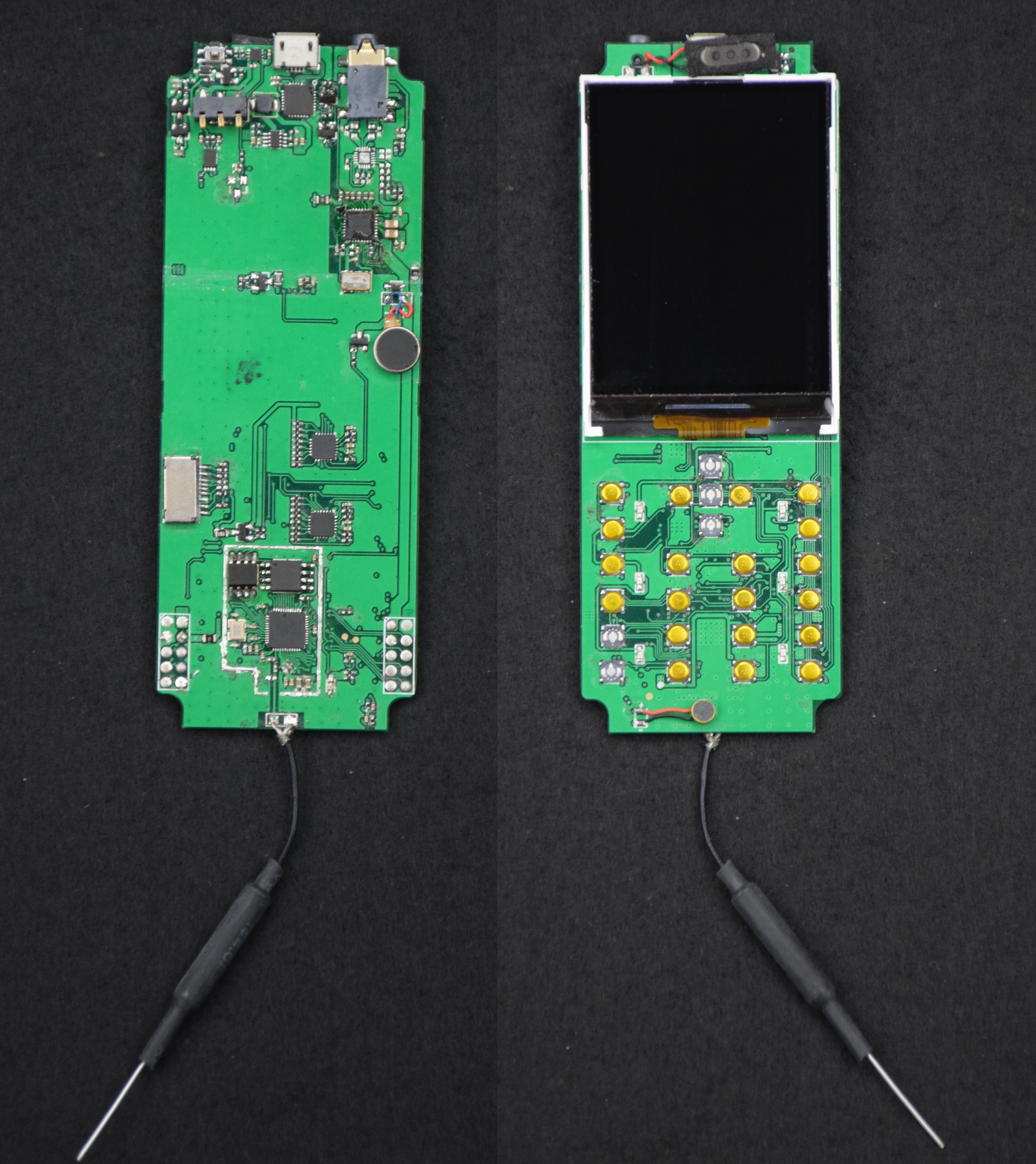
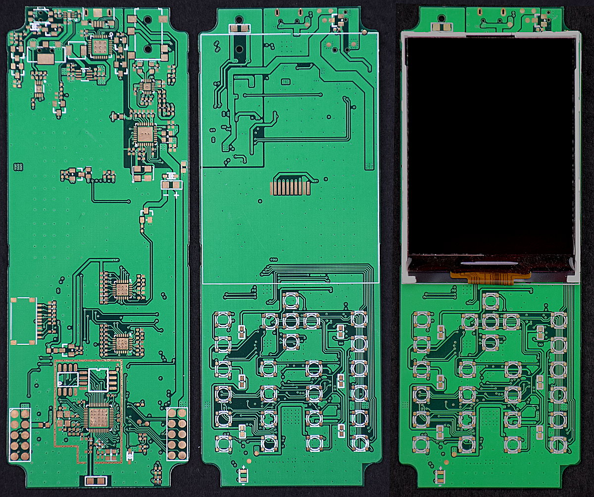
08/14/2018 at 11:44 • 0 commentsThe alpha motherboard arrived. Here’s some quick shots of the front/back + one with the LCD mounted just for fun:
![WiPhone Motherboard]()
WiPhone Motherboard -
Phone Teardowns + Keyboard Survey
08/12/2018 at 15:31 • 1 commentWe have a bunch of cheap phones we’ve been tearing apart, and wanted to post a some pics. Particularly, we’ve been looking to see how they make the buttons and keypads.
Teardown Pics
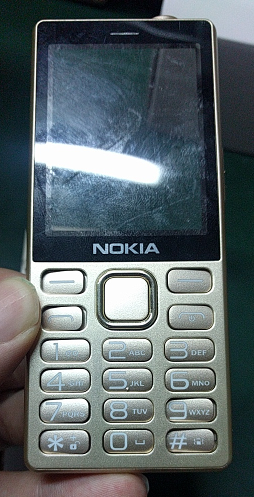
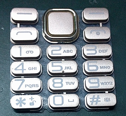
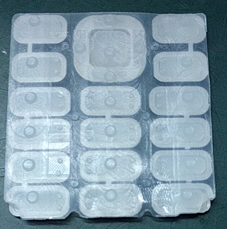
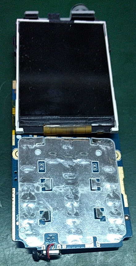
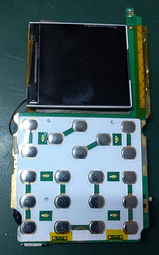
This one is a fake Nokia. Of all the cheap phones we’ve torn apart, the layout of this one seems the most sensible. The keypad feels nice (relatively). The PCB has ample room for components. There aren’t any odd internal bridge pieces or discontinuities in the PCB. The overall size is appropriate. If we are going to try to make a cheap, usable phone, this one seems worth learning from.
![]()
![]()
![]()
![]()
![]()
This is one of those tiny ultra-cheap phones that Westerners tend to call “Gongkai” phones after the article Bunnie Huang wrote.
![]()
![]()
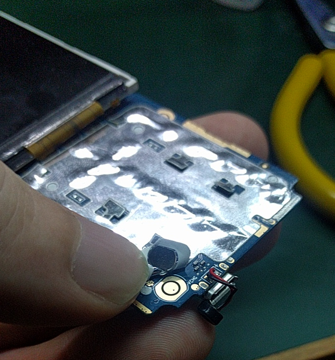
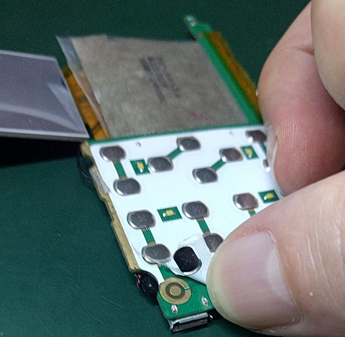
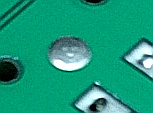
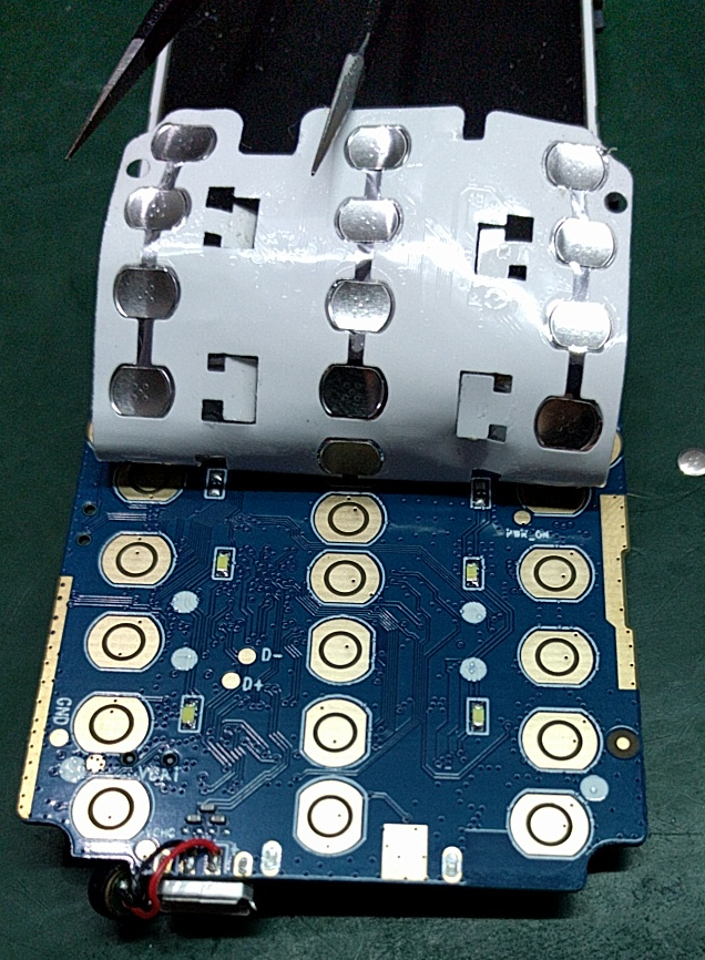
In both cases, the keypad is made using a PCB with exposed traces used as the contacts. Metal domes are used for the buttons themselves, and everything is kept in alignment with an adhesive-backed sheet.
Overview of Keypad Designs and Components
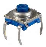
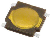
Tactile Switches
![Common Tactile Switch With Frame and Plastic Button]()
![Simple Tactile Switch]()
Tactile switches are typically small momentary-on switches. In keypad applications they are usually sealed, surface mount, and low profile. Some versions have a small frame and plastic button, while others are basically just a metal dome adhered to a set of contacts.If you are designing a high volume product with a keypad, tactile switches actually aren’t that common due to the extra cost relative to the next few options. But for lower volumes they are often used since they are durable, come in known actuation forces and heights, and easy to work with.
Separated Switches
Most higher volume applications use a separate system where the circuit traces are directly bridged by a contact. Often the contact is more or less integrated into mechanical keypad. All of the phones we’ve torn apart use this style of switch.
Contacts
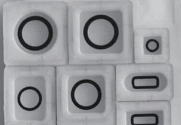
Printed Contacts
Printed contacts are cheap and have a short design life. One example of printed contacts would be a silicone keypad that is silkscreened on one side with conductive ink. The ink is usually located on bumps on the underside of the keypad that align with the contacts on the circuit. If you’ve ever had a remote control with buttons that stopped working well, it probably used printed contacts.
![Rubber Keypad with Conductive Printing]()
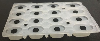
Carbon Pills
Carbon pills are typically made by insert molding them into a silicone compression mold. They have a long design life and are often found in things with a squishy keypad like home phones.
![Keypad with Carbon Pill Contacts]()
![Carbon Pill]()
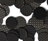
Dome Contacts
Dome contacts are a simple metal dome that gets positioned over the circuit to be bridged. They are often mounted on a sheet that holds them in position. Dome contacts are often used in cell phone keypads due to their compact size, long design life, and snap feel.
![Dome Contact]()
![]()
Substrate Materials
Substrates can be copper traces on a PCB as seen in the image above, or screen printed carbon on a plastic film.
Capacitive Switches
Capacitive keypads have been showing up more often in designs, and operate in a fundamentally different way than a normal conduction based switch. Actuation life for these is theoretically infinite, but they need a relatively large spacing to avoid triggering neighbor buttons and they give no force feedback. Typical applications for these are things like building access panels.
![Capacitive PCB Keypad]()
-
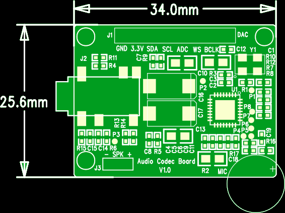
WM8750BL Audio Codec Dev board
08/03/2018 at 11:42 • 0 commentsWe wanted to publish the dev board we made for the WM8750BL audio codec IC.
Design files: 20180702 - audio codec board
Datasheet: WM8750BL_v4.1-1131666.pdfOverview (from the datasheet)
The WM8750BL is a low power, high quality stereo CODEC designed for portable digital audio applications.
The device integrates complete interfaces to stereo or mono microphones and a stereo headphone. External component requirements are drastically reduced as no separate microphone or headphone amplifiers are required. Advanced on-chip digital signal processing performs graphic equaliser, 3-D sound enhancement and automatic level control for the microphone or line input.
Features:
- Stereo / Mono Microphone Interface
- 400mW Speaker Driver (mono)
- Headphone Driver
- Digital Graphic Equaliser
- Audio sample rates: 8, 11.025, 16, 22.05, 24, 32, 44.1, 48, 88.2, 96kHz
- 5x5x0.9mm QFN package
- 1.8-3.3V Supply
The design is in PADS. Everything is there to fabricate it yourself. BOM, gerbers, PDF schematic + PADS schematic and layout.
Currently the audio quality is not very good. There's a good chance that's due to the digital and analog ground planes not being separated.
Pinout:
Pin 1: GND
Pin 2: VCC
Pin 3: SDA
Pin 4: SCL
Pin 5: ADCDAT
Pin 6: WS
Pin 7: BCLK
Pin 8: DACDAT![WM8750BL Breakout Board]()
WM8750BL Breakout Board -
Audio Codecs?
07/25/2018 at 12:01 • 0 commentsA: it's a file format
B: it's an encryption method
C: it's a format converter
D: it's a little wizard that lives in 3.5mm holesThe answer is actually all of the above, depending on the situation. In all cases it COdes and DECodes audio from one format to another. Sometimes so that the bandwidth/storage size is small but the sound quality is high. Other times it's to convert from a format electronics can understand (1's and 0's) to one our ears can (analog waves).
Software Codecs
In software, an audio codec is associated with the familiar MP3, AAC, OGG file extensions that store compressed audio on a hard drive or flash card, or stream it to/from a remote location. This type of codec often concerns itself with compression, saving storage space or bandwidth. The codec is typically a software library, and different codecs optimize for different levels of fidelity, compression, and computational complexity.
Hardware Codecs
A hardware codec is typically an IC that handles converting analog audio between an analog waveform and a digital signal. Sampling rate and bit depth control the signal fidelity, and usually the signal is not compressed at this stage (though it can be). The digital output of a hardware codec is usually a hardware bus like I2S, I2C, SPI, or AC-Link.
We tested a few different codecs and ended up with a system that looks like this:

WiPhone Audio Codec Block Diagram Chips we tested:
ES8316 from Everest Semiconductor:
Bought this on a pre-made dev board and never got it to reply to us. We think the little wizard died.
ES8316
WM8731 from Wolfson Microelectronics:
Also on a pre-made dev board. This one works, but doesn't have a driver for an external speaker.

WM8731 WM8750BL, also from Wolfson:
We had to make a custom PCB to try this one. It's more complex to control (lots of registers), but has mic in, headphone out, and speaker driver, which completely solves our analog sound requirements. Currently it's running on a separate dev board. There are some noise issues that are most likely related to not separating digital and analog ground planes, but it seems to be functioning well otherwise.

WM8750BL
-
Making a call
07/24/2018 at 14:10 • 0 commentsWe successfully called an Android phone. Most of the features we want to unclude are either fairly straightforward or a proof of concept exists in another project. Calling, however, is a pretty big chunk of the functionality that seems to be unique to this project, and our number one goal at the beginning is to prove it can work without big issues.
ESP32 WiPhone
The WiPhone project is an open source mobile IP phone. WiPhone is intended to be hackable, modular, cheap, and open, while remaining usable.