 Fernando Zablah
Setup
The first thing you need to do is go to the Ubidots for Education websiteand create an account. You can sign in directly if you already have a Twitter, Github, Google or Facebook account.

When you have already created your account you will have access to your token, bu clicking on your username at the top right corner and clicking on API Credentials. Save your token, as we are going to use later on.

Ubidots Dashboard

Token key censored, because I dont want strangers to control my home lights randomly
Jason App
The app can be downloaded from the Play Store, it is available in english and spanish.
Copy your Ubidots token into the app, by tapping the settings tab, pasting it in the Ubidots key field and tap the save button.

Settings tab
_cduYWnHhvr.jpeg?auto=compress%2Cformat&w=680&h=510&fit=max)
Ubidots Key Field
_T1rBzAgKJr.jpeg?auto=compress%2Cformat&w=680&h=510&fit=max)
Saved Key in Jason
Now we need to configure a device, go to the devices tab, and tap the add button. Enter a name, preferably the name of the area where the lights are, so you can say "Turn on the kitchen lights". On the ESP32 I/O Pin choose "5", which is going to be the NodeMCU (internal ESP8266) pin connected to the relay. And tap save.
Making the Hardware
Safety First

In this project we are working with mains voltage (A/C voltage) which is dangerous if you don't know what you're doing, be very careful. NEVER touch ANY part of the circuit or work with it if it is connected to the wall power. If you don't know what you are doing, stop right here or get some help from professionals.
I am only posting this educational tutorial and I am by no means responsible for any injuries or damage you may cause.
Schematics

Schematic designed in Eagle CAD
- Power the NodeMCU by connecting VIN to VCC (5V) and GND pin to GND.
- Connect D8 to one end of the switch and to a 2.2K Ohm resistorconected to GND.
- Connect the other end of the switch to 3.3V as the NodeMCU can only handle that voltage in its I/O Pins.
- D1 to 2.2k Ohm resistor to the base of the NPN transistor
- Negative DC of the relay to the colector of the transistor.
- Transistor emitter to GND.
- PositiveDC of the relay to 5V.
- Negative of light bulb to one AC pin of the relay.
- Positive of bulb to AC Live (AC Positive).
- OtherAC pin of relay to Neutral (AC Negative).
NOTE: VCC 5V is going to be supplied from an usb cable connected to a simple phone transformer charger.
Breadboard
_vvTgCj6VlN.jpeg?auto=compress%2Cformat&w=680&h=510&fit=max)
Breadboard without external components (AC, switch and USB power supply)

Breadboard without external components (AC, switch and USB power supply)

Breadboard without external components (AC, switch and USB power supply)
The switch can be a simple toggle switch or a wall switch, it just needs to detect if the user changes its state so we can still control the lights with a normal switch.

Wall Switch Front
_dyvvk58ycq.jpeg?auto=compress%2Cformat&w=680&h=510&fit=max)
Back of switch
The switch that I used has double throw, we only need one, so I connected its pin 1 to 3V of the NodeMCU and pin 2 of switch to NodeMCU pin D8.
_k5ToKxqRMr.jpeg?auto=compress%2Cformat&w=680&h=510&fit=max)
Switch connected to breadboard using jumpers
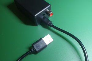
The power supply is going to be a phone wall charger of 5V with a stripped usb cable.
_EChhLVAVuR.jpeg?auto=compress%2Cformat&w=680&h=510&fit=max)
Power connection with jumpers and alligators
By controlling the ground connection with the relay we can control the AC status of the light bulb.

AC light bulb connections (Neutral to relay1, relay2 to negative of light bulb, live to positive of lightbulb)
_uGuSZaE24t.jpeg?auto=compress%2Cformat&w=680&h=510&fit=max)
Alligators comming from the light bulb to relay
Code
Before you use the source code, you need to download some libraries:
- Arduino core for ESP8266 (Read the "Installing with Boards Manager" step)
 Iulian
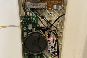
 Christoph Winkler
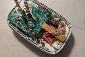
 Gigawatts
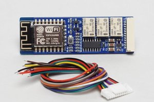
 DM
DM