Close
0%
0%

Z80-MBC2: a 4 ICs homebrew Z80 computer

Homemade 8MHz Z80 SBC, 128kB banked RAM, RTC, SD (HD emulation), Basic and Forth interpreter, CP/M 2.2 and 3, UCSD Pascal, Fuzix and more...

Similar projects worth following
The Z80-MBC2 is an easy to build Z80 SBC (Single Board Computer).It is the "evolution" of the Z80-MBC (https://hackaday.io/project/19000), with a SD as "disk emulator" and with a 128KB banked RAM for CP/M 3 (but it can run CP/M 2.2, QP/M 2.71, UCSD Pascal, Collapse OS and Fuzix too).

It has an optional on board 16x GPIO expander, and uses common cheap add-on modules for the SD and the RTC options. It has an "Arduino heart" using an Atmega32A as EEPROM and "universal" I/O emulator (so a "legacy" EPROM programmer is not needed).

It is a complete development "ecosystem", and using the iLoad boot mode it is possible cross-compile, load and execute on the target an Assembler or C program (using the SDCC compiler) with a single command (like in the Arduino IDE).

* NOTE TO THE READER *: Due to a text size limitation of the Hackaday. io site a few chapters have been moved to "Log files". In this case you have just to click on the link of the chapter's title to open a new tab and read it.
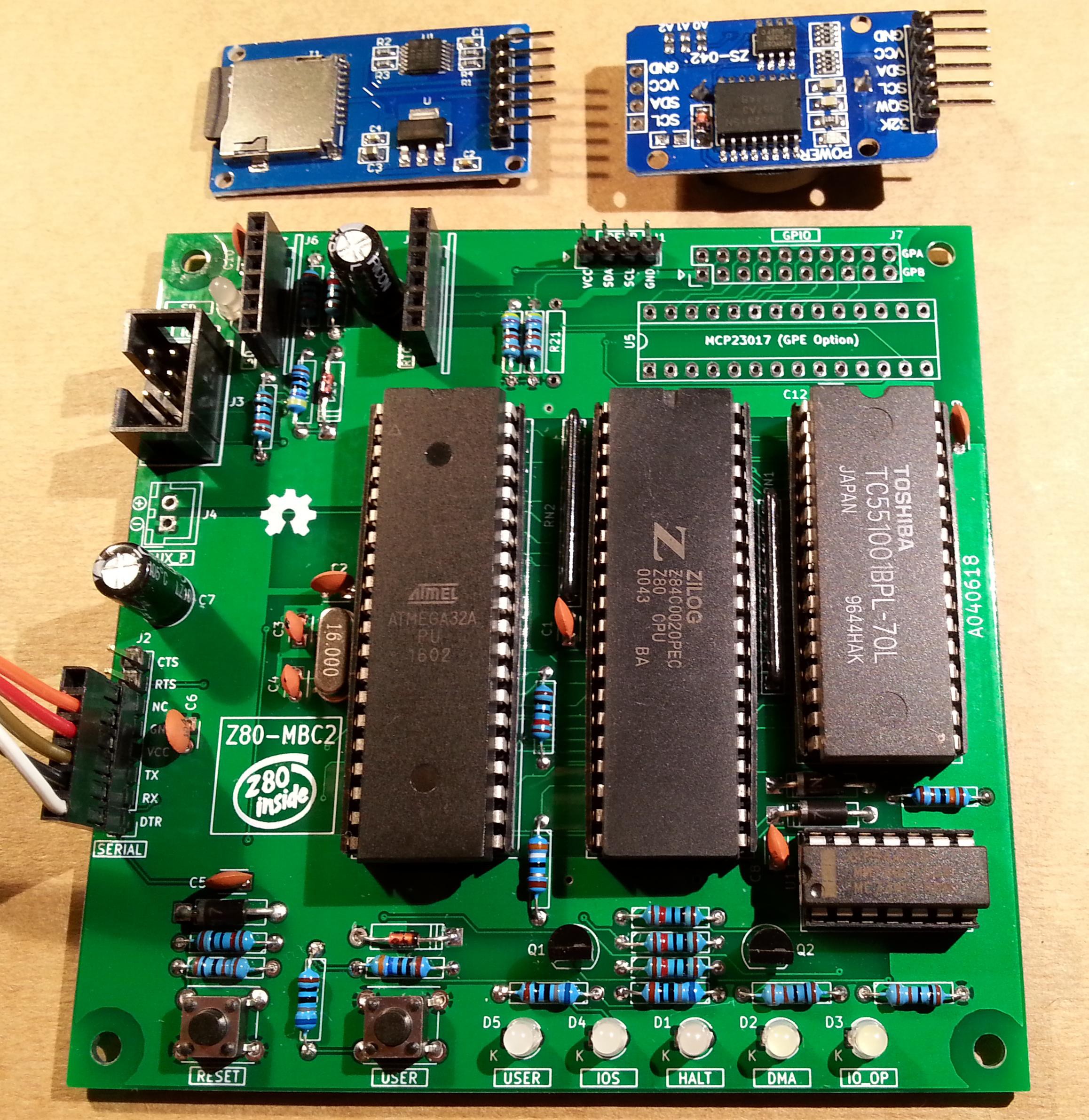
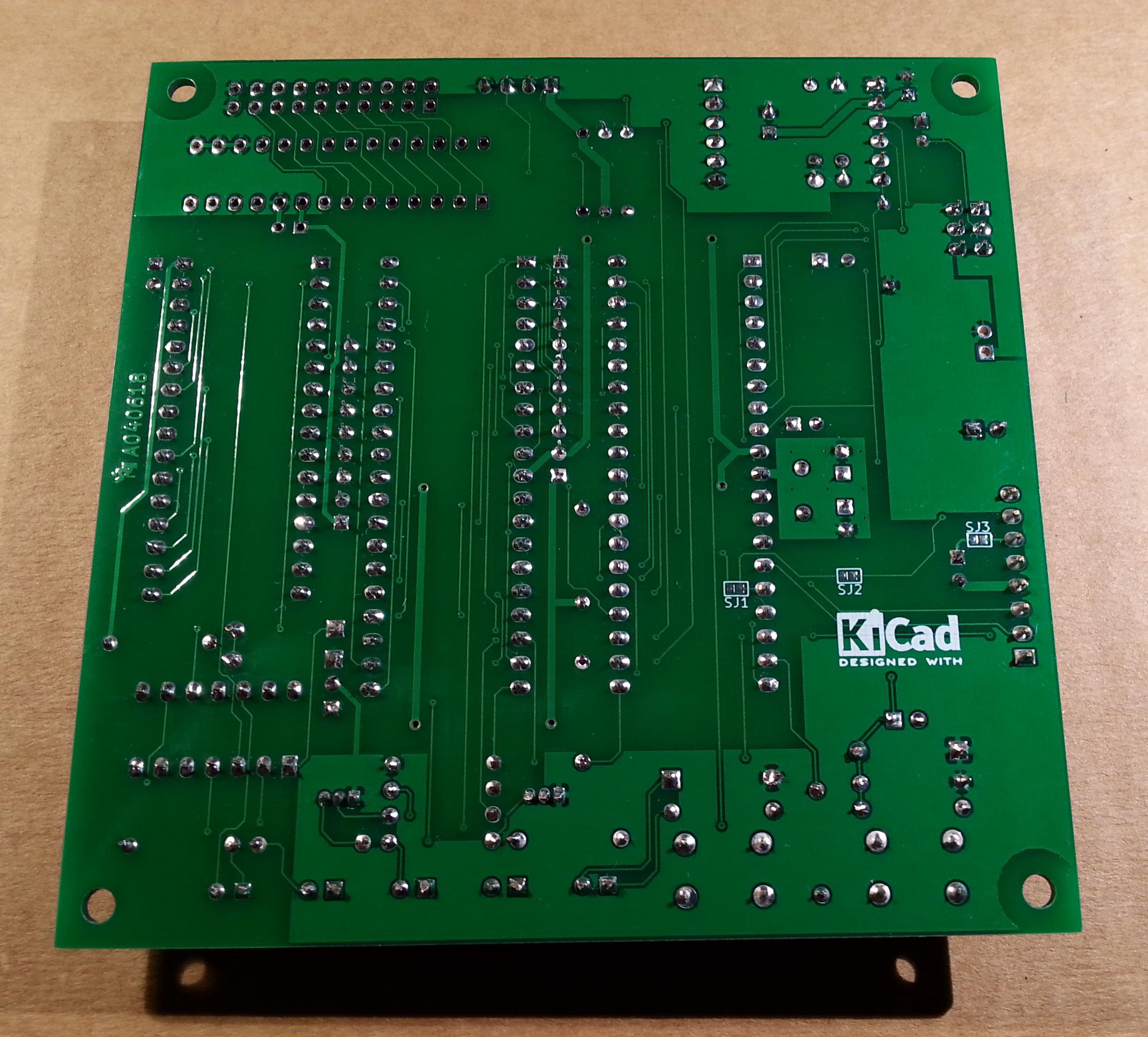
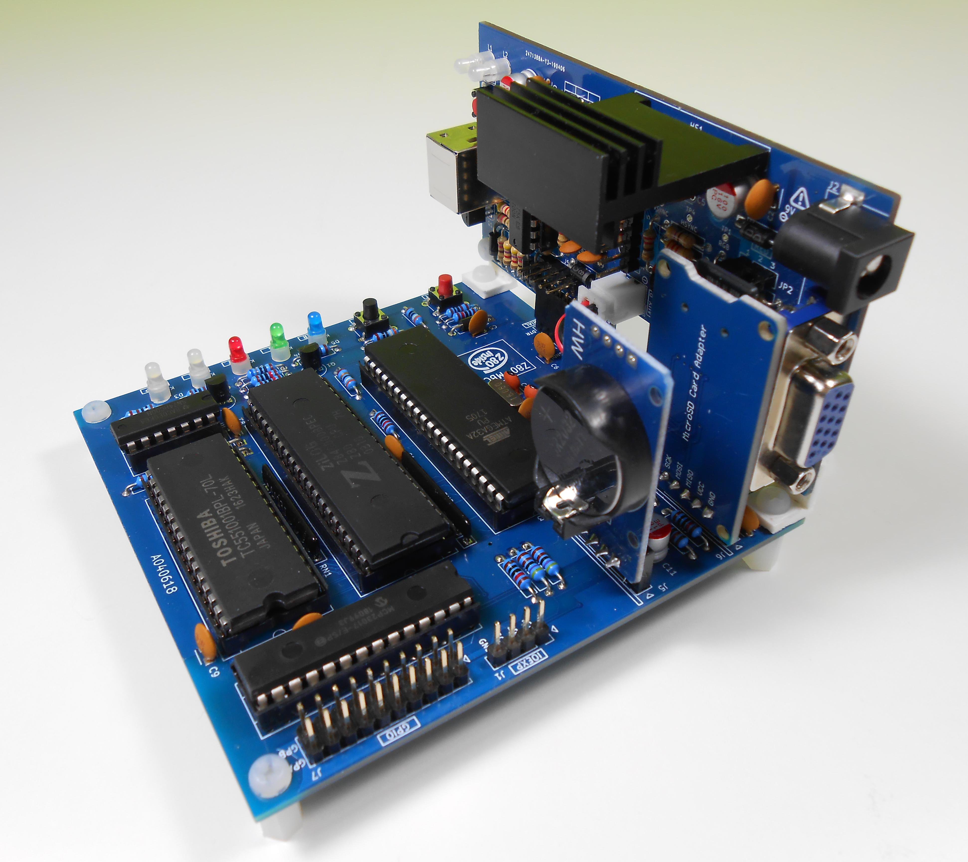
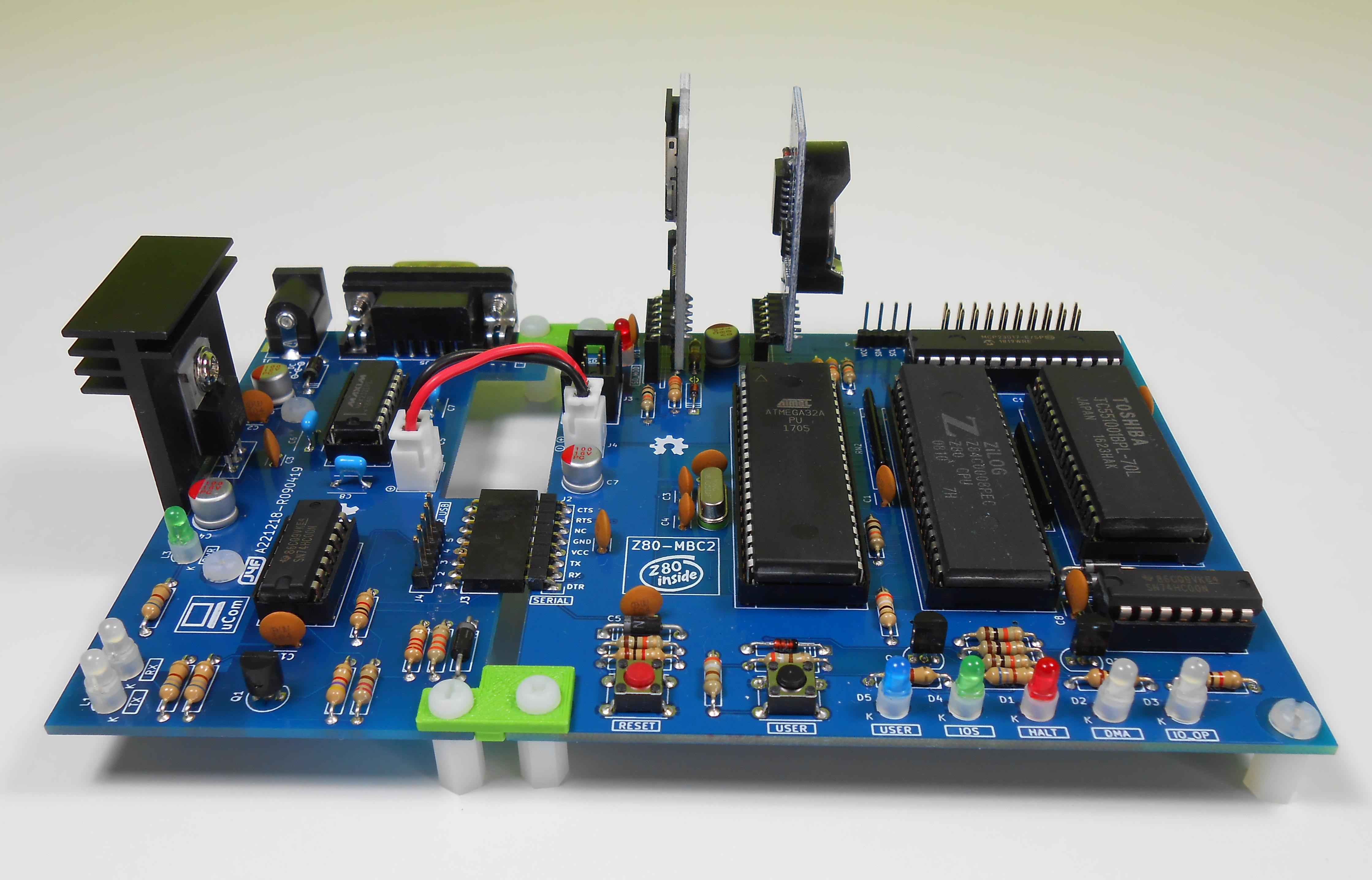

* * HARDWARE OVERVIEW * *

The needed ICs for the "base system" are:

  • Z80 CPU CMOS (Z84C00) 8Mhz or greater
  • Atmega32A
  • TC551001-70 (128kB RAM)
  • 74HC00

If you want the 16x GPIO expansion (GPE option) add a MCP23017 too.

The schematic and the BOM are attached in the Files section. The MCU Atmega32A is used as universal I/O subsystem, as Eeprom, and as reset and 4/8MHz clock generator for the Z80 CPU.
Inside the Atmega32A it is flashed an Arduino bootloader taken from here, and it is possible to use the Board Manager of the Arduino IDE to "import" it.

Flash the Arduino bootloader at first (with the method you prefer), next you can upload the IOS "sketch" (the I/O Subsystem that interacts with the Z80 bus and "virtualizes" the EEPROM and all the peripherals seen by the Z80 CPU) using Arduino IDE.

You can use the on board ICSP port J3 (also called ISP port) to write the bootloader, but remember to disconnect any other connector when using it. Also both SD and RTC modules (if present) must be removed from the board when the ICSP port is in use.

As clock source for the Z80 CPU it is used the 16MHz Atmega32A oscillator, so the "external 16MHZ osc." bootloader variant must be chosen when flashing the bootloader from the Arduino IDE!.

The 74HC00 is used as RS flipflop to stop the Z80 CPU during I/O operation, giving the needed time to the Atmega32A to interact with the Z80 bus, and as part of the MMU.

Note that only the CMOS version of the Z80 CPU can be used here. This because only CMOS version, under given condition that are respected in this schematic, has logical levels compatibles with Atmega32A and 74HC00.


NOTES ABOUT THE COMPONENTS

You should use a  Z80 CMOS speed grade of at least 8MHz for full speed, but setting the clock speed at 4MHz you can use a 4MHz Z80 CMOS version too (or you can try to overclock it at 8MHz...). The 74HC00 can be substituted with a 74HCT00 if you already have one. The RAM chip TC551001-70 can be substituted with any suitable 128kB SRAM).

Please note that the USER led  * must * be blue or white (or pink... I've some pink leds that seems to have a Vf like blue one. May be I'll do a board with them...) just to be sure that V(forward) is >= 2.7V (otherwise the USER key may not work as expected).

The J4 connector (AUX_P) is used as auxiliary power connector when an add-on board (uCom or uTerm) is connected.

The three solder jumpers (SJ1-3) on the bottom side are not currently supported and must  be left opened (as stated in the schematic).


THE GPE OPTION (GPIO CONNECTOR)

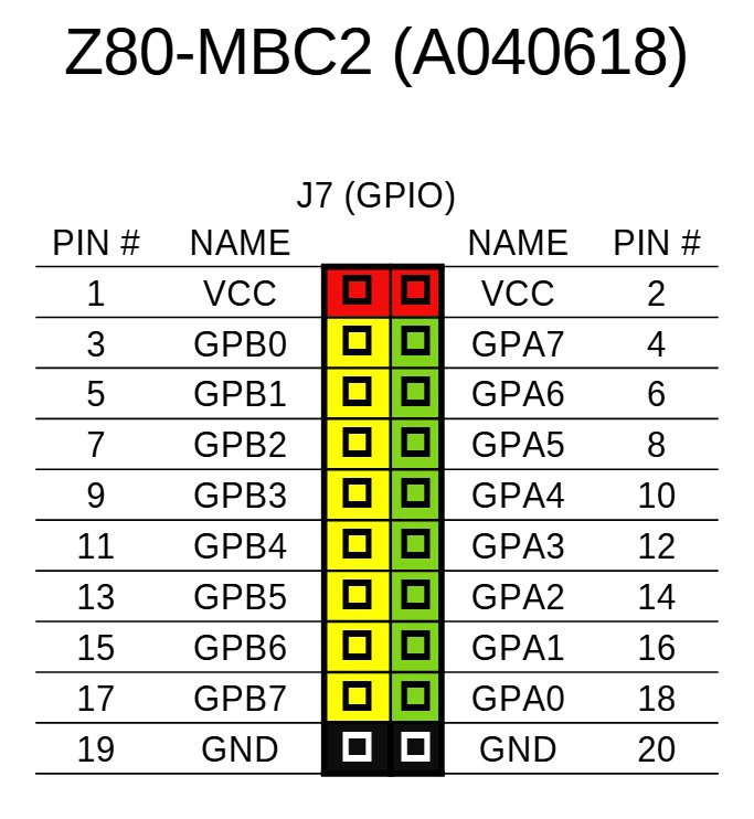
It is possible to choose to populate on the PCB a GPIO port expander (U5) to add 16 bidirectional GPIO pins. The GPE option (see the schematic) can be used with the SPP Adapter board (see the paragraph: SPP (STANDARD PARALLEL PORT) ADAPTER BOARD).

The pinout of the GPIO (J7) connector is:

THE SERIAL PORT

The  SERIAL port (J2, see schematic) can be connected with a TTL-RS232 adapter, or with a serial-USB adapter.
I've used a serial-USB adapter that acts also as power source for the Z80-MBC, and has the DTR signal for the "autoreset" driven from the Arduino IDE. For a terminal that has a serial TTL port no adapter is needed.

Of course to upload a "sketch" from Arduino IDE you need to use a serial-USB adapter connected to the SERIAL port.

Note that the RTS and CTS pins of the SERIAL port are not currently supported and must be left not connected (as the NC pin!).

The 3V3 pin of the serial-USB adapter must be left disconnected  (if present).

You should use those Serial-USB adapters that have the DTR pin on the connector. It is suggested to have also the CTS/RTS signals available for future upgrades.

Please note that all the pin...

Read more »

Z80-MBC2 User Manual - D081023-R280424.pdf

Z80-MBC2 User Manual

Adobe Portable Document Format - 11.66 MB - 04/28/2024 at 15:52

Preview

SD-S220718-R290823-v2.zip

The content of the microSD needed to run CP/M 2.2, CP/M 3.0, QP/M 2.71, UCSD Pascal, Collapse OS and Fuzix with IOS S220718-R290823 (More info in the Changelog.txt file inside)

Zip Archive - 5.81 MB - 10/06/2023 at 10:40

Download

S220718-R290823_IOS-Z80-MBC2.zip

The sketch for the IOS (with the needed libraries). Unzip into a folder and open the .ino file (with Arduino IDE). IOS must be uploaded into the Atmega32A flash. Adds support for Fuzix OS and the SPP Adapter board (more info in the changelog inside the .ino file).

Zip Archive - 43.75 kB - 09/24/2023 at 11:59

Download

S220718-R290823_IOS-Z80-MBC2.ino.with_bootloader_atmega32_16000000L.hex

The sketch for the IOS in executable format (.HEX) with the bootloader. This executable file is intended for use with a programmer as the Atmel Ice or AVRISPmkII or others (Fuse bits: High Byte 0xD6, Low Byte 0xAF, Lock Byte 0xCF)

x-hex - 59.90 kB - 09/24/2023 at 12:04

Download

SPP Adapter board - A240721-R270921.zip

All the documentation needed to build the SSP (Standard Parallel Port) Adapter board (A240721-R270921) including schematic, PCB assembling guide, Gerber files for PCB production. PCB is 55mm x 60mm 2-layers.

Zip Archive - 747.10 kB - 09/24/2023 at 15:10

Download

View all 13 files

  • 1 × See the file "A040618 BOM v2.ods" in the FILES section.

  • * * ​USING THE TASM CROSS ASSEMBLER * *

    Just4Fun10/09/2023 at 14:07 0 comments

    * * USING THE TASM CROSS ASSEMBLER * *

    The TASM cross assembler (Windows CLI application) can be used for various CPU. It can be downloaded from here. The on-line manual is here.

    Using the TASM cross assembler it is possible setup a toolchain to program the Z80-MBC2, doing all the development on a PC and uploading the code with the serial port and then executing it on the target Z80-MBC2 with iLoad.

    After the download of the TASM zip file, unzip it into your working directory (it is the folder where your assembler source files are stored) and to assemble an user source give the command:

    tasm -s -h -c -g0 -80  <Your_source.asm> out.hex

    It will be created the out.hex file (Intel-hex formatted executable file).

    Now you can upload and execute out.hex using the iLoad boot mode of the Z80-MBC2.

    Remember that iLoad will take the first address of the Intel-Hex stream as the starting address of the program, and after the loading will jump to it.

    At this point you can follow the same steps to create an automated toolchain described in the paragraph "SDCC: SETTING UP AN AUTOMATED TOOLCHAIN (WINDOWS)".


    TASM: USING AUTOBOOT

    If you want create a binary file to use with the Autoboot boot mode you can generate it with the command:

    tasm -s -h -c -g3 -80   <Your_source.asm> out.bin

    It will be created a flat binary file out.bin. Then rename out.bin as autoboot.bin and copy it into the root of the SD used by the Z80-MBC2.

  • * * ​USING THE SDCC CROSS COMPILER * *

    Just4Fun10/05/2023 at 13:27 0 comments

    * * USING THE SDCC CROSS COMPILER * *

    Using the SDCC (Small Device C Compiler) cross-compiler it is possible setup a toolchain to program the Z80-MBC2 with the C language, doing all the development on a PC and uploading the code with the serial port and then executing it on the target Z80-MBC2 with iLoad

    SDCC can be found here: https://sdcc.sourceforge.net/.

    After installing it, SDCC needs to be in some way instructed about how to deal with the specific HW of the Z80-MBC2.

    For this reason in the SD image, inside the \SDCC folder, there are two support files: S190818-R011023_crt0.s and S290923_Z80-MBC2.c.

    All the steps needed to configure the toolchain are explained below (we will assume a Windows operating system here, but the steps are similar for Linux):


    STEP 1:

    Copy the two support files S190818-R011023_crt0.s and S290923_Z80-MBC2.c from the SD image (\SDCC folder) to your working directory (it is the folder where your C source files are stored) and compile the first file with the command (from your working directory):

    sdasz80 -plosgff -o S190818-R011023_crt0.s

    It will be created the S190818-R011023_crt0.rel file.


    STEP 2:

    Now it's time to compile the second support file (S290923_Z80-MBC2.c). Here things are a little more complex because this file can be compiled in two different ways which differ depending on whether interrupts are enabled or not.

    The  need to have interrupts enabled or not depends on whether your user program uses them or not.

    To enable the interrupts support compile with the command (from your working directory):

    sdcc -c -mz80 -DZ80MBC2IRQ S290923_Z80-MBC2.c

    Instead to disable the interrupts support compile with (from your working directory):

    sdcc -c -mz80 S290923_Z80-MBC2.c

    It will be created the S290923_Z80-MBC2.rel file.


    STEP 3:

    iLoad uses the first address as starting address for the execution, so the executable file (Intel-Hex formatted) must be in ascending address order. This is not guaranteed by SDCC, so you need to use the srec_cat utility to sort the file. You can download this utility from here: https://srecord.sourceforge.net/  and then you have to copy the srec_cat.exe file into your working directory.


    All done!

    To compile your source file the command is (from your working directory):

    sdcc -mz80 --no-std-crt0 S190818-R011023_crt0.rel <your_source.c> S290923_Z80-MBC2.rel -o temp.hex

    It will be created the temp.hex file (Intel-hex formatted executable file).

    Now to sort the file give the command (from your working directory):

    srec_cat -disable-sequence-warnings temp.hex -Intel -o out.hex -Intel

    This will create the sorted file ready to be loaded with iLoad: out.hex.

    Now you can upload and execute out.hex using the iLoad boot mode of the Z80-MBC2.


    SDCC: SETTING UP AN AUTOMATED TOOLCHAIN (WINDOWS)

    To create an automated toolchain you need another "ingredient", a terminal emulator supporting scripts. Here we will use Tera Term. You can download Tera Term from here: https://ttssh2.osdn.jp/index.html.en.

    After installing Tera Term, from the SD image inside the \SDCC folder, copy into the working directory the following batch files: SDC.BAT and L.BAT.

    Before using the L.BAT batch file you have to adapt two parameters according with the configuration of your PC. 

    Go at line 18 and verify the path where Tera Term (ttermpro.exe) is installed, and at line 19 the number of the COM port used to connect the Z80-MBC2 to your PC.

    You need also to copy the Tera Term script LoadZ80.ttl from the /SDCC folder (inside the SD image) to the directory where Tera Term (ttermpro.exe) is installed, and adapt the parameter at line 15 with the complete path of your working directory in your system.

    Now to compile your_source.c file give the command (from your working directory):

    SDC your_source.c

    and to upload and execute it on the Z80-MBC2 (from your working directory):

    L

    Remember to close the Tera Term window...

    Read more »

View all 2 project logs

Enjoy this project?

Share

Discussions

Cyril V. wrote 08/30/2018 at 00:16 point

I just got my PCBs, they look really good (the solder mask is black).

I got couple to spare. I think selling 2 for $5 plus shipping, PM if interested.

  Are you sure? yes | no

villaromba wrote 08/28/2018 at 13:38 point

The message you get - is that after selecting it or does it just default to that?  OR Do you get full menu if you hold user key dow, then hold reset for a moment - release it and then release user key? If so can you select anything at all from keyboard?

  Are you sure? yes | no

Peabody1929 wrote 08/28/2018 at 19:21 point

After pressing just reset I get:

Z80-MBC2 - A040618
IOS-LITE - I/O Subsystem - S220618

IOS: Z80 clock set at 4MHz

IOS: Loading boot program... Done
IOS: Z80 is running from now


After pressing reset and user and release I get:

Z80-MBC2 - A040618
IOS-LITE - I/O Subsystem - S220618

IOS: Z80 clock set at 4MHz

IOS: Select boot mode or system parameters:

 0: No change (->1)
 1: Basic
 2: Forth
 3: iLoad
 4: Change Z80 clock speed (4/8MHz)

Enter your choice >

After pressing "1" at the prompt I get:

Enter your choice >1  Ok
DEBUG: BootImageSize = 7603
DEBUG: BootStrAddr = 0
IOS: Loading boot program... Done
IOS: Z80 is running from now

  Are you sure? yes | no

Just4Fun wrote 08/28/2018 at 20:46 point

Which method have you followed to flash the bootloader?

  Are you sure? yes | no

Peabody1929 wrote 08/27/2018 at 18:30 point

I finished building my board.  It starts up, outputs messages to the serial monitor but seems to stop after the message: 

"IOS: Z80 is running from now".  

The Z80 clock is set at 4MHz

The boot mode is 1: Basic.

What should I do next to debug the issue?  

  Are you sure? yes | no

Just4Fun wrote 08/27/2018 at 19:49 point

Which method have you followed to flash the bootloader?

  Are you sure? yes | no

Peabody1929 wrote 08/31/2018 at 02:54 point

I have tried two methods of flashing the bootloader.  Each time used a different ATmega 32 part.  Both times the USB interface was a USBTinyISP V2.0.  First time it was connected via a 10 pin cable to a ATmega32 dev board with a 40 pin ZIF, a 10 pin socket and all the pins brought out to headers.  The second time was using a 6 pin cable connected to the ISP connector on the MBC2 board.  In the Arduino IDE v1.8.5 selected the programmer as USBTinyISP (MIghty Core) and click Burn Bootloader.  There were no error messages and the flash was successful.

Unfortunately this made no difference in behavior.

One difference is that I am using a Z84C00020PEC.  This is a 20MHz Z80.  Is there a possibility of a narrow clock pulse glitch that a 8MHz part would never see?

Finally, I think the ATmega32 is operating correctly.  I plugged in a MCP23017 and a new message appeared: "IOS: Found GPE Option".

  Are you sure? yes | no

Just4Fun wrote 08/31/2018 at 07:31 point

I'm using the same Z80 (Z84C00020PEC) on Z80-MBCs and Z80-MBC2s without problems...

And the method you use to flash the bootloader seems correct to me (I use the USBasp, but the USBTinyISP should be ok because you are using the Arduino IDE "facility" to burn the bootloader, so should be not possible to have fuse bits configuration errors because they are managed by the IDE...).

Try to change a different Atmega32A, just to be sure that your part is not faulty.

After that it seems that the problem can be the CPU or the SRAM, because you arrive at the point when the program should be loaded into SRAM and the Z80 starts to execute it.

  Are you sure? yes | no

Peabody1929 wrote 09/01/2018 at 01:02 point

IT WORKS!!!!  I replaced every chip except the SRAM.  Following your suggestion, I replaced the SRAM.  The board now works perfectly; BASIC comes up and runs.   I am a happy camper.  Thank you for the help!

Tom

  Are you sure? yes | no

Just4Fun wrote 09/01/2018 at 07:47 point

Great! Can you tell me the exact part name  of the faulty SRAM?

BTW: Thinking to add a SRAM test....

  Are you sure? yes | no

Peabody1929 wrote 09/01/2018 at 18:32 point

The faulty SRAM part number is: HM628128ALP-7  The replacement part is: HM628128LP-12.  The replacement part is an older generation and slower part.

If you like, I can send you the failing part by mail.

P.S.  I have some HM628128BLP-7 parts as well.  Perhaps in the next build I will give these a try.

  Are you sure? yes | no

Just4Fun wrote 09/03/2018 at 09:40 point

Thanks, but it is enough if you could just keep it. So if I have the time to write a memory test it is possible to use the faulty SRAM for testing...

BTW: may be that this can interest you: https://twitter.com/Just4Fun_J4Fun/status/1036289202265247745 :)

  Are you sure? yes | no

Julian wrote 08/26/2018 at 20:24 point

Thinking of using this design as a basis for experimentation -- do you know if it's likely to run OK on breadboard, or is the PCB essential?

  Are you sure? yes | no

Just4Fun wrote 08/27/2018 at 15:44 point

Yes it can be done. Just the quartz oscillator could be "critical" on the breadboard, but if you use the internal oscillator (8MHz) you shouldn't find any problem.

You can give a look to the previous Z80-MBC on breadboard too (https://hackaday.io/project/19000-a-4-4ics-z80-homemade-computer-on-breadboard).

  Are you sure? yes | no

villaromba wrote 08/11/2018 at 07:51 point

Built up my board yesterday - no output!! until I realised I had clock fusebits inverted!! Reprogrammed AVR (TL866) and then it worked immediately, pleased all hardware/soldering was 100%!!. Put my AVR on a ZIF, just fits nicely. RTC should be here over weekend. I already have a Pololu SD so hoping that will be ok when ready to fit. Thanks again J4F for another excellent design and look forward to where it might develop.

  Are you sure? yes | no

Just4Fun wrote 08/11/2018 at 08:02 point

Thanks!

I think this may interest you... :) : https://twitter.com/Just4Fun_J4Fun/status/1027158962242772992.

PS: Check carefully that the Pololu SD has the 3.3V regulator and level shifters on board, and how to connect it as it is different from that one I've used here.

  Are you sure? yes | no

villaromba wrote 08/11/2018 at 10:39 point

Great!!! - it works with the Pololu SD card, with level shifters (all I had) just needed to make small adapter to ensure pin compatibility. 

  Are you sure? yes | no

villaromba wrote 08/12/2018 at 15:42 point

What will be the longer term plan for CP/M files on the SD Card e.g will it be able to read files from Peter Schorns Z80 simulaior (https://schorn.ch/)  or Z80 pack (https://www.autometer.de/unix4fun/z80pack/)?  OR ???

  Are you sure? yes | no

Just4Fun wrote 08/12/2018 at 16:34 point

The first link is interesting as i didn't know anything about it. (the second is well known).

About the SD,  I'll use "disk files" each equivalent to a disk of 512 tracks of 32 sectors. A sector is 512 bytes large, as the SD physical sector. So any SW that can "understand" this can read/write files on it.

E. G. using cpmtools with the correct parameters will work (I hope...) :)

I've to manage a "deblocking" algorithm for CP/M2.2, because it can use natively only 128 bytes sectors (CP/M 3 can use 512 bytes sectors natively, as far I know...), and this will take "some" time...

  Are you sure? yes | no

Just4Fun wrote 08/05/2018 at 11:57 point

For those interested I've set up a twitter account to follow the "day by day" developments (and others things too)...: https://twitter.com/Just4Fun_J4Fun

  Are you sure? yes | no

Norihiro Kumagai wrote 08/05/2018 at 07:23 point

I have one comment, some N-MOS CPU also work well, at least, NEC upd780-1 works well on both Z80-MBC, and Z80-MBC2.  If someone have one or more N-MOS Z80, It might work on these boards.

  Are you sure? yes | no

Norihiro Kumagai wrote 08/05/2018 at 07:19 point

I built a PCB and see the BASIC prompt and run a Blink BASIC program.  Quite good.  Thank you very much. If you are interested in it, please refer my blog https://dip40.wordpress.com/  or my tweet (@tendai22plus).

  Are you sure? yes | no

Just4Fun wrote 08/05/2018 at 09:27 point

You have a very good blog. It's really a pleasure read it!

  Are you sure? yes | no

Just4Fun wrote 08/02/2018 at 17:02 point

HI all, and thanks for your comments!

Here IOS booting from SD: https://farm2.staticflickr.com/1793/43090760674_723f2eb475_o.png

Now starting to play with CP/M 2.2...

  Are you sure? yes | no

Mark Jungwirth wrote 07/31/2018 at 17:05 point

I just ordered 5 PCBs from https://www.pcbway.com/project/shareproject/Z80_MBC2__4ICs_homemade_Z80_computer.html

Is anyone planning a component order that others could tag along on?

Awesome work, J4F!!!

  Are you sure? yes | no

john wrote 07/31/2018 at 19:28 point

Hey Mark - I've got the parts from the original board that I'm planning to reuse, but  if you've got an extra board you'd be willing to part with, I'd be willing to buy one from you.

  Are you sure? yes | no

Mark Jungwirth wrote 07/31/2018 at 20:01 point

John, not a problem.  I only paid for ePacket delivery so it might be a couple of weeks.  My cost is $3 and I should be able to send USPS first class for less than $1.

  Are you sure? yes | no

Jeff Davis wrote 09/05/2018 at 06:51 point

I'm going to do a big parts order, if you haven't ordered yours yet. I also have bunch of parts in boxes I'll pull from and use, can send you whatever I have spare. I probably have a lot spare.

  Are you sure? yes | no

john wrote 07/28/2018 at 20:52 point

Great job!!! Again!

  Are you sure? yes | no

villaromba wrote 07/28/2018 at 19:51 point

Ordered pcb from EasyEDA. Looking forward to start building in a few weeks. It will be good to have the SD Card this time. Be so much easier to load up!!!

  Are you sure? yes | no

Peabody1929 wrote 07/29/2018 at 04:01 point

Could you share how you uploaded the gerbers to EasyEDA?  I get "Bad File Format".

  Are you sure? yes | no

villaromba wrote 07/29/2018 at 08:28 point

When I ordered (got transferred to JLCPCB) it asks for Gerber files - so I just uploaded the zip file from this site, kindly provided by Just4Fun. All went through ok without any problems. So maybe you should download zip file again and try a new upload to EasyEDA in case one or the other corrupted.

  Are you sure? yes | no

nemfield wrote 07/28/2018 at 12:16 point

Excellent work. There is elegance in simplicity , and you nailed it. I'll be ordering boards asap. 

  Are you sure? yes | no

Norihiro Kumagai wrote 07/28/2018 at 02:37 point

I ordered 10 PCBs with your garber data to fusionPCB.  I am quite looking forward to receiving them to start soldering.  Thank you for your kindly preparing.

  Are you sure? yes | no

Just4Fun wrote 07/28/2018 at 06:26 point

Thanks! Happy soldering... :-)

  Are you sure? yes | no

Jose Manuel Arenas wrote 07/27/2018 at 18:44 point

Very nice project. I love it.

  Are you sure? yes | no

Just4Fun wrote 07/27/2018 at 19:22 point

Thanks!

  Are you sure? yes | no

Does this project spark your interest?

Become a member to follow this project and never miss any updates