Theory of operation:
The miniSolar is designed to take in power from a 2-3 watt solar panel, charge a small lithium battery, and charge a device. Since USB devices tend to draw a constant current, the battery buffer is required to supplement the solar power when it's insufficient to charge the device by itself. This has the additional benefit of allowing the solar panel operate at full efficiency to charge the battery when the load is low.
A microcontroller is used to run the converter with Maximum Power Point Tracking (MPPT). It also contains logic that can enable or disable the USB output, preserving the battery and allowing intermittent operation when the solar input is lower than the demanded load.
The intended mechanical configuration is to build a "pocket", with the solar panel as one side, the electronics at the bottom, and space inside for a phone or other device. This way the miniSolar doubles as a phone protector.
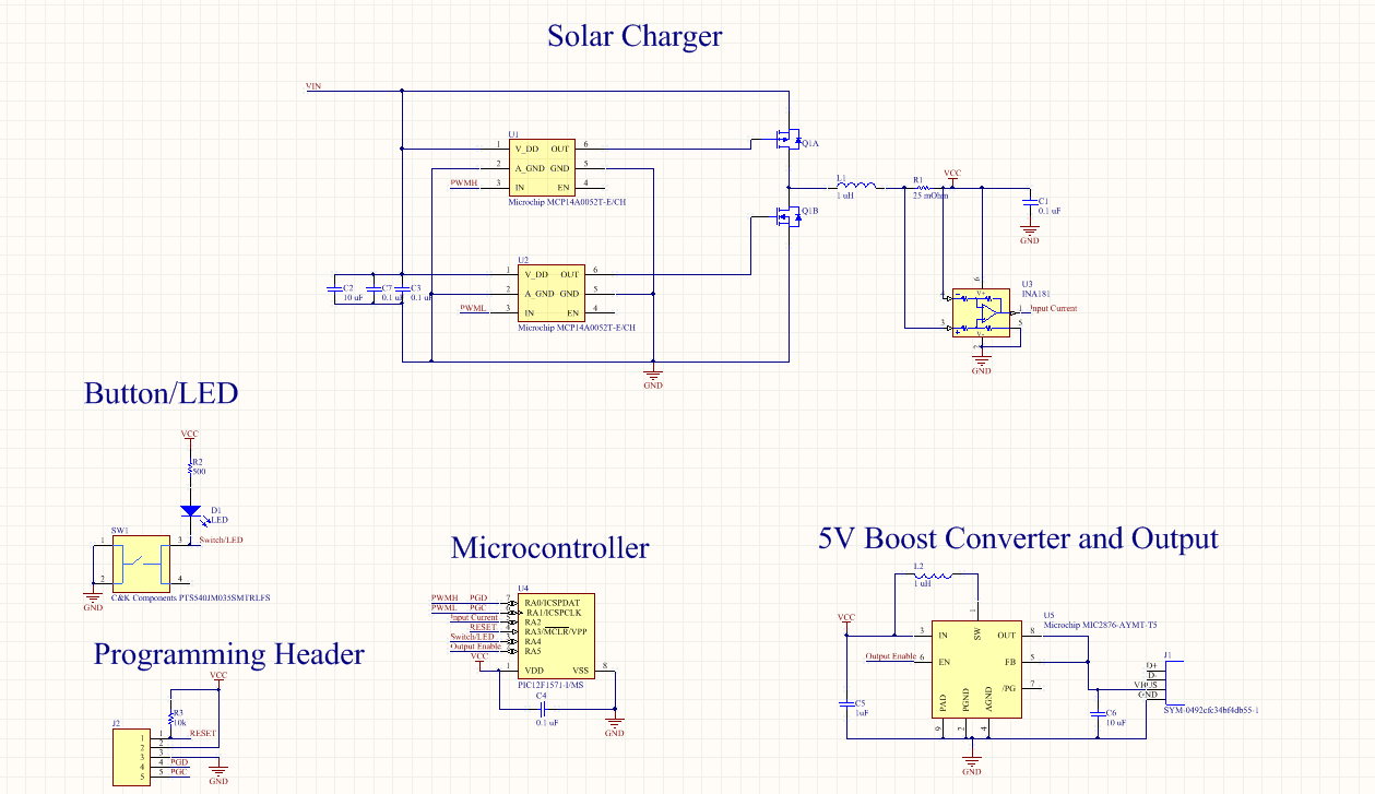
Circuit Design:
At 21 components, this is definitely one of my simpler designs.
This circuit contains:
- A PIC12 microcontroller, with 8 pins. This little guy is pushed to its limit, with some pins getting multiple uses!
- A programming header for the PIC
- A button and LED. Since I'm short on pins, these guys have to share, with the side effect that pushing the button will turn on the LED. The LED is to double as a make-shift flashlight.
- A 5V boost converter IC. In the spirit of "keep it simple", I let an IC do the work of generating 5 V from the battery.
- A custom synchronous buck converter. This is easily the trickiest part. I intend to implement MPPT, so measuring the current from the converter is a must. Due to the low voltages/powers involved, a boot-strap high-side NFET driver was deemed infeasible. Therefore, a PFET is used for the high-side gate, sacrificing low on-resistance for simpler and more efficient gate drivers.
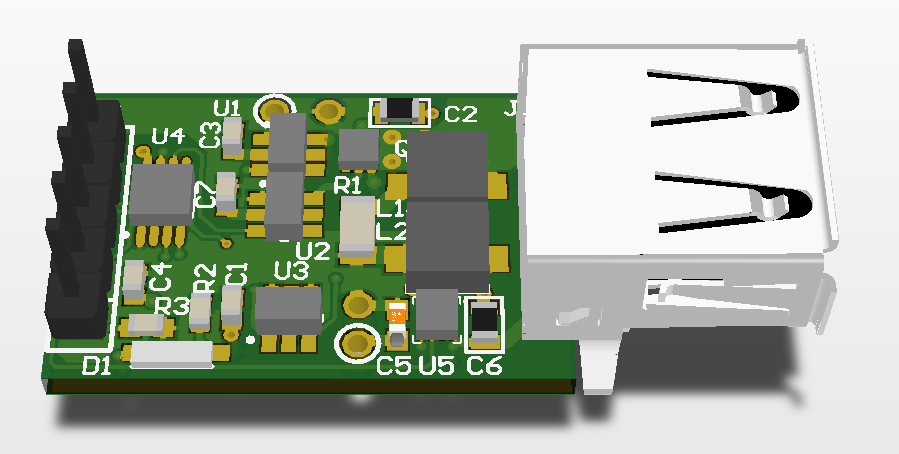
PCB Design
I designed the circuit and PCB in Altium CircuitMaker, my hobby tool of choice. I hold Altium as the gold standard of user interface, and once you've gotten used to it it's hard to use anything else.
The first prototype is just slightly over the One Square Inch requirements at 1.1 inch, which helps the USB port have more mechanical support. I cut it down a touch to fit the rules of the competition, and now the dimensions are 1.000 by 0.665 inches.
This is a two layer board with all the components on one side (except the button, which is on the back so that it's reachable). This circuit has a job to do, so no frills or fancy art, yet CircuitMaker renders it beautifully.
This CircuitMaker project can be accessed at https://workspace.circuitmaker.com/Projects/Details/Peter-Thompson-3/Simple-Solar-Charger
Next Steps
OSH Park just notified me that the boards are back from the fab! In a few days, I'll be able to build this up and test it out. I have a bit of code to write and an enclosure to draw up as well.
Discussions
Become a Hackaday.io Member
Create an account to leave a comment. Already have an account? Log In.