Why use an EFM8 MCU
The great thing about the EFM8 line from Silicon Labs is that they’re very inexpensive. A look at Mouser will show that the EFM8BB10F2G in QFN20 is the lowest cost MCU on the market in singles and in-quantity for the average engineer and maker. It is very hard to beat the EFM8BB10F2G with 16 GPIOS, built in configurable 12bit ADC, 4 16-bit timers, comparators, UART, SPI, 2kB of program space, 256 bytes of ram, and on-chip debugging. Also, the EFM8 line is very easy to get working as it needs very little support hardware. And for a few cents more, you can get even more ram and program space.
Prerequisites for the EFM8
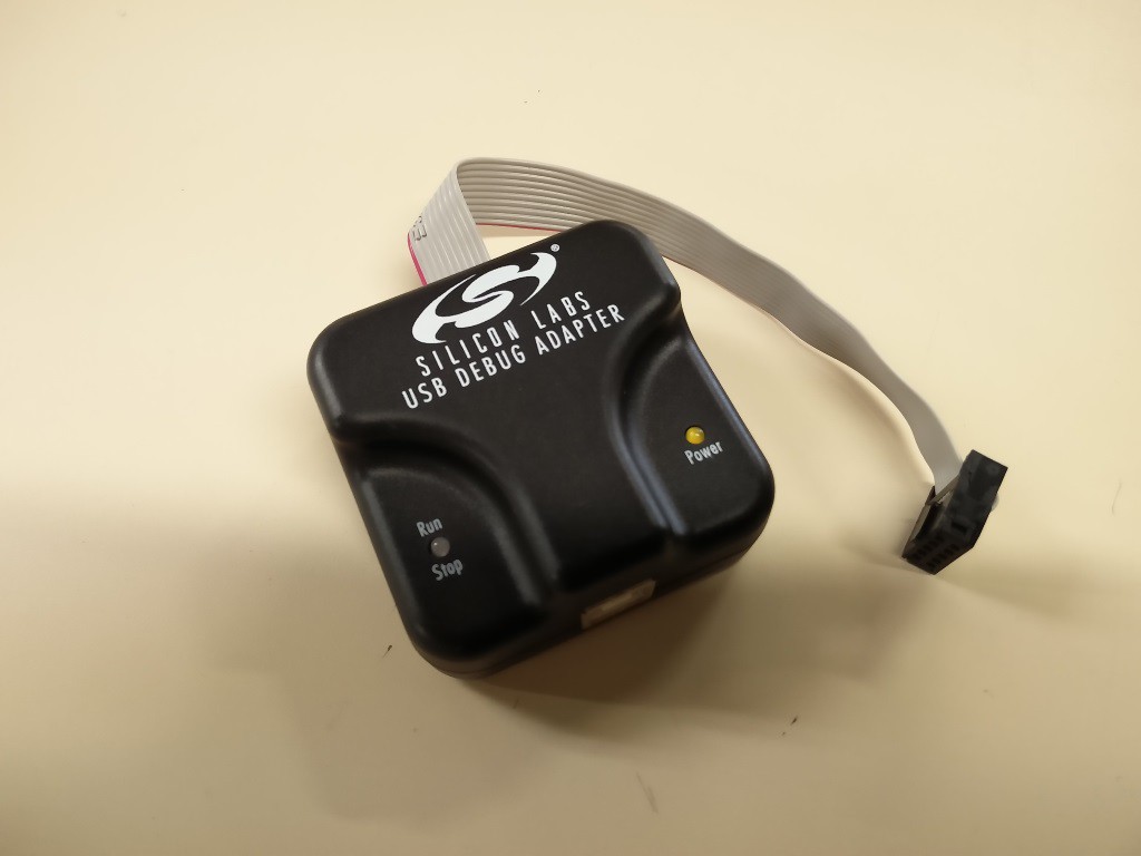
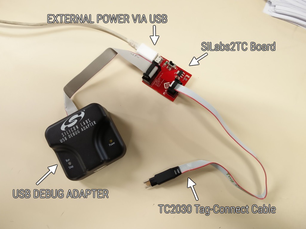
To program the EFM8 chips you will need a USB Debug Adapter for C8051 MCUS from Silicon Labs (See Figure 1). Mouser also stocks this adapter for $35 (at the time of this article). Since I am a fan of Tag-Connect cables, I will be using the SiLabs2TC board. Figure 2 shows how the SiLabs2TC board works. This board connects the USB Debug Adapter and an external power source to a Tag-Connect TC2030 cable. I will be designing the EFM8 example board with the SiLabs2TC board in mind. There is a factory bootloader but we will cover that at another time.
Example board for the EFM8
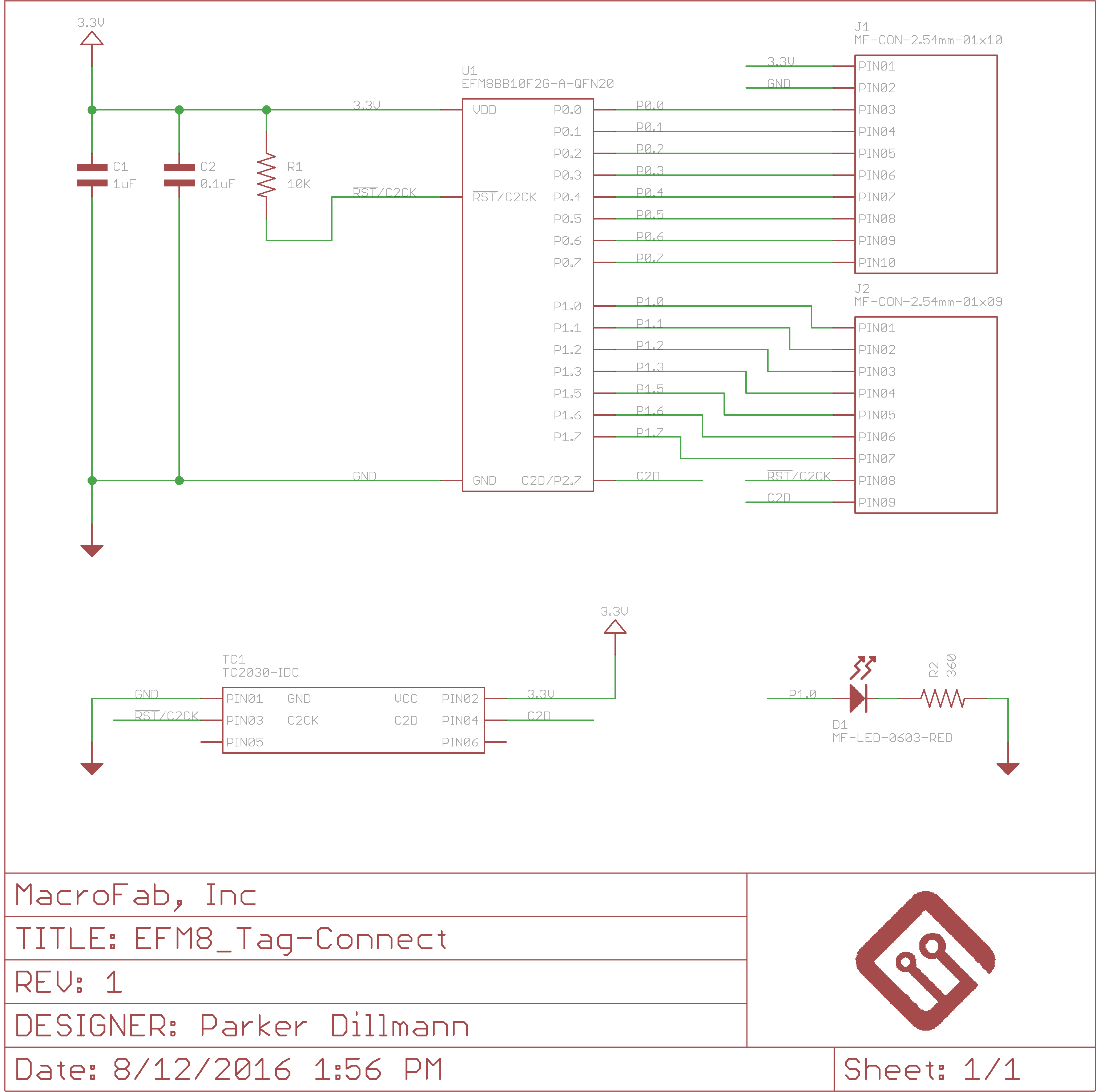
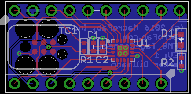
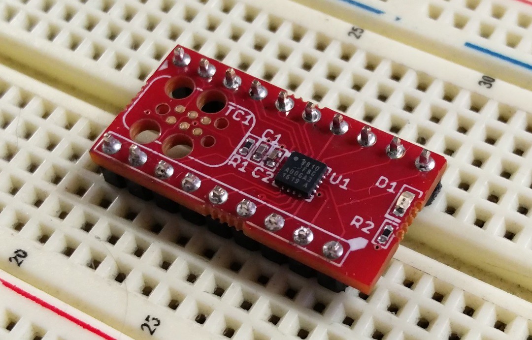
Most EFM8 MCUs just need two bypass capacitors of 1μF and 0.1μF and a 10K ohm pull-up on the reset line to get it working. The internal oscillator clocks at 24.5 MHz with a ±2% accuracy which is fine for most applications. For the board, I decided to go as minimalistic as possible. The board has just 1 extra LED and resistor to provide an on-board debug LED. Figure 3 and Figure 4 show the schematic and board layout for the example board.
Using the EFM8_Tag-Connect example board
Whats next?
That will conclude the basics of getting an EFM8 based MCU project working hardware-wise. The next article in the series will be on how to use Silicon Labs Simplicity Studio to get the built on LED on the EFM8_Tag-Connect example board to blink.
 Parker

 Saimon
 arief ibrahim adha
 Jon Thomasson
 Jeremy g.
Sounds like fun! The rules state that "All parts have to be sourced from Mouser [...]". What counts as parts in the project? Say, just as an example, that I want to build a Rube Goldberg machine that includes, among other stuff, a Commodore 64, ropes, pulleys, a bucket of water, LEDs and a hot dog. Is this idea disqualified as only the LEDs are available at Mouser?