This page describes a prototype board for the Atmel Mega644 or Mega32 (PDIP) MCU. It includes a power supply, crystal clock, and generous bypass capacitors. A six-pin header allows flash memory programming from an STK500 or AVRISPmkII. All port pins are brought out to a single row of vias on 0.1 inch centers. A single 34 connection, SIP header plug could be used to attach ths row to another board or to a solderless breadboard. All 32 port pins, plus Vcc, and ground, are available. A separate interface is provided for serial communication.
Board Version 12 for 2012
The board layouts are shown below. The design for next revision (v13-2013): main board, usb board, serial board.
The ExpressPCB design files above require a free software download to modify or to order directly from expressPCB.
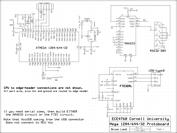
Note that the schematic includes both the serial and USB interfaces, but you would never use more than one at a time.
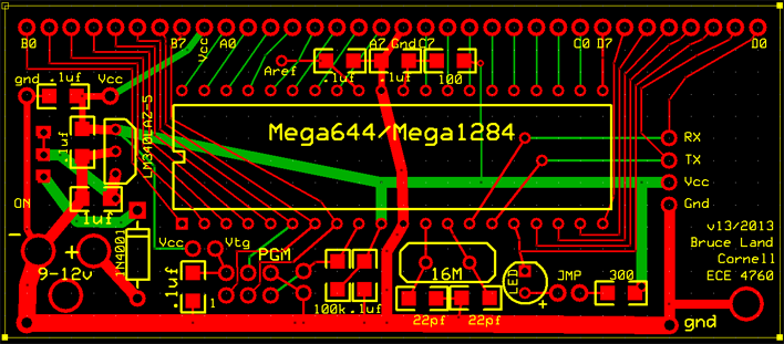
The main board.
The four-pin header to the right of the board matches either the serial or USB board below (and in the future a radio board).
The board is 0.3 inches shorter than the last model because header pins
for Aref and VccUSB were deleted along with the solder pads for the
TSSOP USB chip.
Instructions for building the board are below.

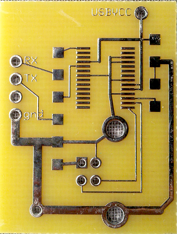
The USB and serial boards.
Build ONE of these ONLY IF you need serial communication. Instructions for building the boards are below.
Note that VccUSB is brought out to a pin on the board, but DOES NOT connect to Vcc on the main board.
When using the serial-USB connection:
- You must turn off the microcontroller, then:
- Plug in the usb cable. The PC should recognize a USB serial connection.
- Then: turn on the microcontroller.
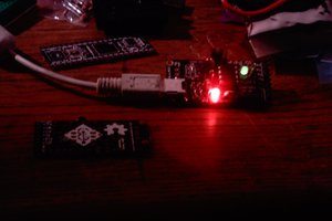
The populated boards showing the headers (on the bottom) which attach the boards to the main cpu board.
A top view of the boards is below.

Version 12 Construction suggestions:
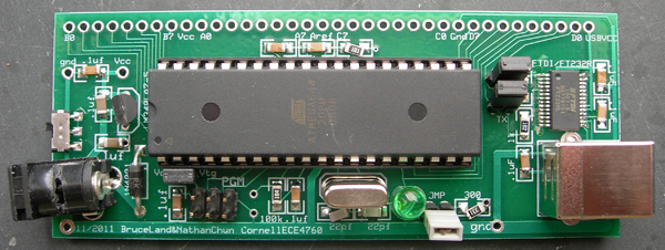
Study the photo below before you build. There are more photos of very similar
(but older) boards near the end of the page.
Generally mount the thinnest components first because the tall components
get in the way of soldering flat components.
- Solder all capacitors and resistors on the board.
See Hints and Tips for prototyping with Surface Mount Devices. Also good is SMT101.
Note that there is one 1.0 uf capacitor (below the regulator) and two 22pf capacitors below the crystal. The rest are 0.1 uf. - Add the headers for TX, RX, LED, Vcc-Vtg, and programming.
For the progamming header, use one two-row header, not two single-row headers. - Add the regulator, power switch and power plug and diode.
- If you are going to hardwire a battery to the board, then don't mount the power plug.
- You could add a remote power switch, rather than mount one on the board.
- The power switch should lay flat, it should not be on edge (see photos).
- Test the power supply before you go any further! Vcc should be 5 volts +/-0.05 volts.
Note that this board (unlike the STK500) requires 9-12 volts, DC, with positive on the power connector center pin.
This year's version puts a 1N40001 diode between the positive power input and the switch. The diode ensures that the system is not destroyed by reverse polarity (but it does not work). - Add the MCU socket.
Always use a socket for the MCU. - Add the 16 MHz (or 20 MHz) crystal.
- You can add an (optional) reset button by connecting a normally-open pushbutton
between the two small vias to the right of the programming header.
When you close the pushbutton, you short the RESET pin to ground. - I strongly suggest adding the LED and jumper for debugging. Toggling
port pin D.2 will flash the LED to let you know that the MCU is running.
- For a Mega644 with serial or USB adaptor, this GCC program (and uart.c and uart.h) will test the system by blinking the LED, sending numbers to the terminal and accepting single keystrokes from the terminal.
- For the Mega644, with just the LED is on the board, then this ...
 Bruce Land


 WingTechCorner
 Parker
 Ethan Durrant
Hey Bruce! Man oh man, this is fantastic, I just bought the development board from MCUdude for the ATmega1284 chip, but this actually may be the solution I've been looking for. I need all these components to fit to 1 small enclosure so it can connect to the CCD detector inside my spectrometer.