Kris Winer
-
New Product Brief
12/01/2020 at 00:04 • 0 commentsUSFS Modules and carrier boards are now available at Tindie.
![]()
-
MAX32660 Motion Coprocessor - MMC5983MA Low Noise Magnetometer Results
08/11/2020 at 23:51 • 4 commentsUpdate
We have been moving forward with commercial sales of the MAX32660 motion coprocessor on Tindie. We are working closely with our initial users to address the remaining "kinks" in the product that inevitably come to light when real people start using something to solve real problems. Many Thanks to our early adopters!
After resolving some initial issues, it is clear that the basic proposition of the motion coprocessor is holding up:
- Superior performance from advanced sensor calibration done under controlled conditions and stored in the EEPROM
- On-board dynamic hard iron correction to maintain calibration validity once deployed in the field
Having said this, the question always remains: Can we reasonably do even better? One thing we wondered about was the magnetometer. Even with appropriate low-pass filtering it seems a bit noisy... So we suspected that heading accuracy and stability could improve further with a better magnetometer. Moreover, our current choice doesn't support a wide-enough operating temperature range for automotive applications. This second point is not a serious limitation at the moment. However, as part of a previous project, the notion of a motion coprocessor for automotive use was discussed. We determined that all of the necessary components were available in AEC-Q100-qualified versions except for a compatible magnetometer.
Kris periodically searches commercially available MEMS magnetometers for potential candidates. He recently identified the MMC5983MA from MEMSIC as a possible option. It boasts 18-bit resolution and AEC-Q100 qualification with a 400kHz-capable I2C interface. The current MAX32660 motion coprocessor product uses the LIS2MDL magnetometer offered by ST Micro. This particular triaxial magnetoresistive magnetometer responds over a full scale range of +/-50G at 16-bit resolution. The operating temperature range is -45 to +80C. The typical RMS noise level we measure for this magnetometer is ~0.35uT on each axis. The resulting RMS heading noise is ~0.1deg under static heading conditions. The MMC5983MA is also a triaxial magnetoresistive sensor, has a full scale range of +/-8G at 18-bit resolution and can operate between -40 and 105C. The nominal RMS noise is estimated to be 0.04uT for each channel.
MMC5983MA Testing and Results
From the perspective of specifications, the MMC5983MA does look attractive. It does cover a much smaller full scale range but +/-8G should be adequate as the geomagnetic field is ~0.5G. This means that the MMC5983MA can tolerate a hard iron offset up to ~7G without saturating, which should be adequate for the vast majority of applications. We did find the advertised reduction RMS noise and 18-bit resolution to be compelling, despite the nearly 2x increase in price compared to the LIS2MDL.
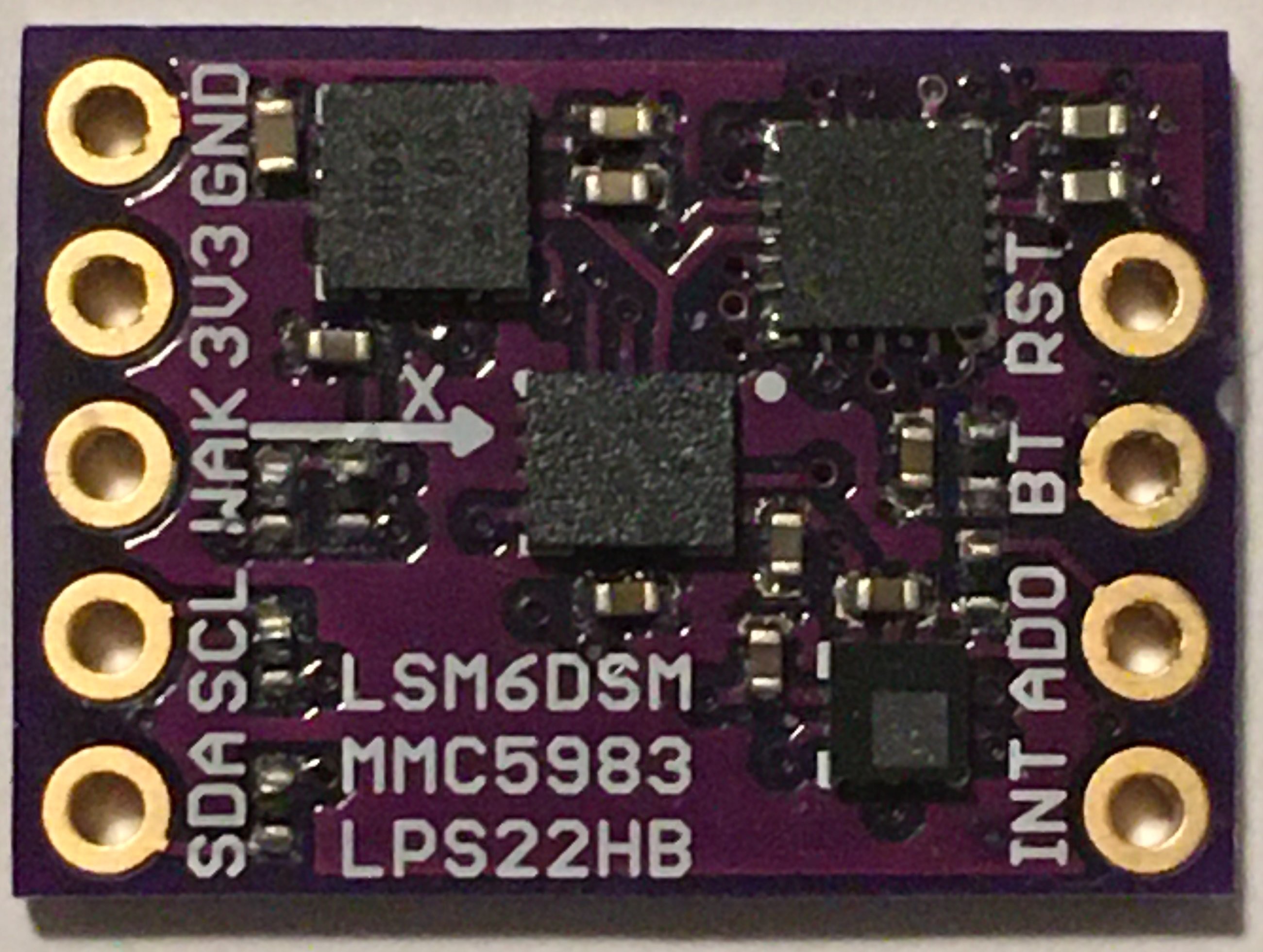
In order to satisfy our curiosity, Kris designed a prototype version of the MAX32660 motion coprocessor using the LSM6DSM accel/gyro, MMC5983MA magnetometer and LPS22HB baro:
![]()
And I wrote a version of the firmware to support the MMC5983MA. This chip has a few quirks regarding the data ready interrupt but it does deliver high quality data at 100Hz without disrupting data collection from the other sensors on the MAX32660's master I2C bus.
The initial data sets from this variant of the MAX32660 motion coprocessor verifies the noise improvement promised in the MMC5983MA datasheet. The magnetometer's RMS noise level ranged from 0.02 to 0.03uT across the three axes, just about 10x better than the results observed for the LIS2MDL. This improvement in magnetometer noise resulted in an RMS heading noise level of 0.015deg under static heading conditions. This is about a 7x improvement over the current LIS2MDL version.
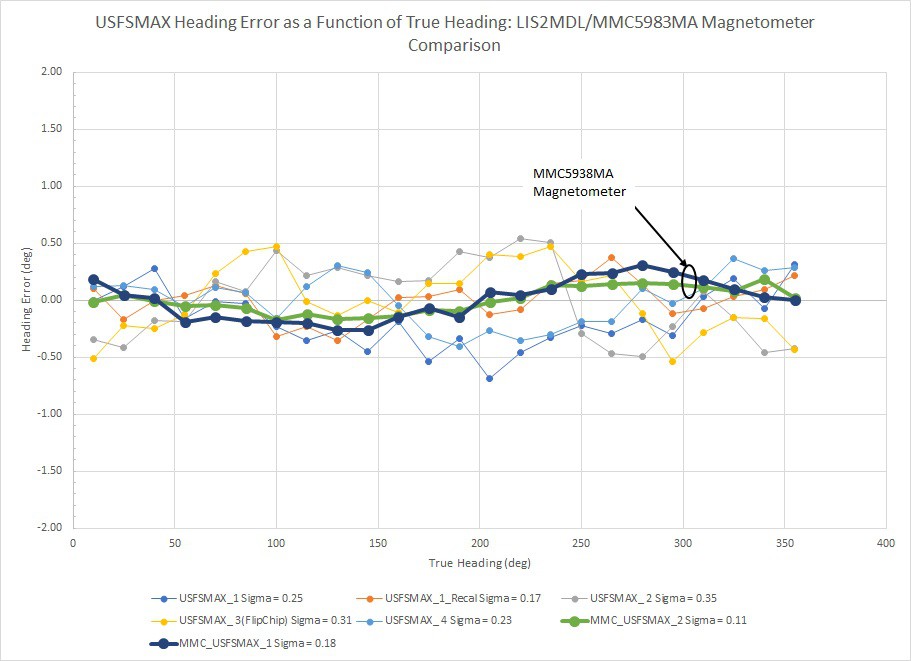
Finally, we wanted to see if the MMC5983MA's reduced noise and improved precision would translate into better RMS heading error. Kris built two MMC5983MA-based prototype units and I subjected them to the same bench calibrations and precision goniometer characterization described in earlier project log entries. The plot below shows heading accuracy as a function of true heading as shown in a previous project log entry:
![]()
The same LIS2MDL-based results are shown as in the earlier project log entry and the additional data from the two MMC5983MA-based prototype units are plotted simultaneously and highlighted for clarity. The results from the MMC5983MA-based units are excellent (0.11 and 0.18deg RMS heading accuracy) and show significantly less sample-to-sample noise around the compass dial.
Discussion
The higher performance of the MMC5983MA magnetometer does indeed translate into tangible improvement of the heading estimate, as we suspected. The noise level of the magnetic field component measurements is actually slightly better than advertised (~0.025uT vs. 0.04uT specified in the datasheet). But not only does this translate into a lower noise level of the heading estimate, we also see improved RMS heading accuracy. It is difficult to determine the magnitude of this improvement from a sample size of two but I would make an initial guess of ~50%. It also appears that the accuracy of the MMC5983MA magnetometer is sufficiently better as to justify the 18-bit resolution that the sensor supports. This all highlights a fundamental truth: Sensor fusion algorithms can give you the best estimate of which the sensors are capable... but no better. If you need improved results, that starts with the quality and stability of the sensors and the accuracy of their calibration. There is no amount of math that can fix poor quality data...
At this point in time we do not have clear plans to bring out a MMC5983MA-based MAX32660 motion coprocessor as a separate product. It is not clear what the level of interest is to move from ~0.35deg RMS heading error down to ~0.2deg... Especially in light of the ~2x higher component cost of the MMC5983MA. However, if you see an application where the higher performance or AEC-Q100 qualification would be justified, please don't hesitate to leave a comment...
-
Unit-to-Unit Variation and On-Board Residual Hard Iron Error Correction
12/20/2019 at 00:44 • 1 commentUnit-to-Unit Heading Accuracy Variation
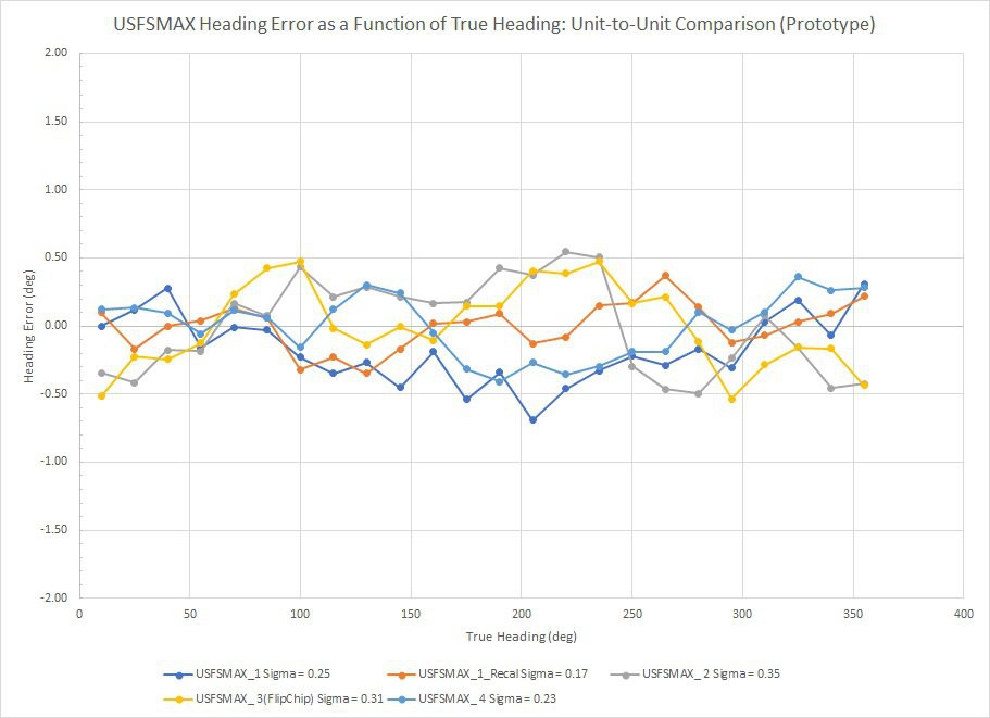
In my last log entry I mentioned the need to characterize the unit-to-unit variation of heading accuracy among professionally manufactured MAX32660 motion co-processor boards. We are still waiting for delivery of our initial production runs, so in the mean time I decided to characterize the four prototype units I had on-hand. I used the same precision goniometer, calibration method and experimental procedures described in my previous log entry. The plot below shows heading error as a function of heading.
Results from a total of four units are included in this plot with two data sets from "Unit 1" representing two different trials of the calibration method. The RMS heading error ranged between 0.17 and 0.35 degrees. If anything we would expect professionally manufactured units to have more precise location/alignment of the MEMS sensor chips on the circuit board than these hand-built prototypes. So if placement of the accel/gyro and magnetometer chips effects post-calibration heading accuracy, we might potentially see less unit-to-unit heading accuracy variation on production units than what I have measured here. However, the nature of the 24-point tumble calibration described earlier should robustly correct accel/gyro/mag misalignment. So I would expect these results to be a representative sample of the MAX3260 motion co-processor's heading accuracy capability. I will perform similar measurements on a sample from our first run of production units when they arrive early in 2020.
![]()
On-Board Real-Time Hard Iron Error Correction
Throughout the slate of heading error characterizations I have performed, I noticed that heading error performance degrades slightly when the magnetic environment differs from the exact calibration conditions. This effect is not gross but is more like degrading from ~0.26 to ~1 degree RMS heading accuracy. This illustrates a typical complaint regarding IMU calibration: The stellar results generated during calibration on the test bench are seldom translated to the real performance in the field. Analysis of the heading error plots showed that the additional error is hard-iron-like in that it has a period of 360 degrees. This means the magnetometer response surface is still spherical but is displaced from the origin.
The heading error results shown above indicate that the suite of MEMS sensors we are using (LSM6DSM and LIS2MDL) are stable enough to deliver ~0.26 degree RMS heading accuracy... So degrading to ~1 degree by incidental changes in the IMU's local environment should be correctable, especially since the additional error takes the form of a hard iron offset (the easiest to estimate and correct). The MotionCal (Freescale) magnetic calibration algorithm embedded in the MAX32660 is quite capable of dealing with this additional incidental hard iron error but it is too computationally intensive to run in parallel with the main AHRS fusion filter in real time.
Instead of just saying, "Oh well, such is life..." I decided to investigate the possibility of a simple, computationally efficient method of fitting a sphere to the locus of run-time (Mx, My, Mz) data points and extract estimates of the residual hard iron offsets. I found this reference which presents a practical embodiment of a method for geometrically fitting the "best sphere" through a 3D ensemble of data points. Upon examination, I particularly liked this method because 1) It is analytic and does not need to be solved iteratively and 2) Adding data to the point ensemble to be fitted only results in using more memory without increasing the computational load on co-processor MCU. The center point and radius of the best-fit sphere are calculated from a set of running sums that are cubic in X and Y. Executing a spherical fit after adding a new (Mx, My, Mz) data point consists of:
- Calculating the necessary cubic and quadratic terms from the Mx, My, Mz data
- Adding new terms to the running cubic, quadratic and linear term sums
- Using the running sums to calculate the new center point and radius estimates by simple algebraic manipulations
So the total computational load is fairly light and is the same for the first and Nth data points.
I tested the efficacy of this approach by:
- Programming the analytic sphere-fitting method on the host MCU
- Subtracting the sphere-fit center point coordinates from each (Mx, My, Mz) data point
- Programming a duplicate AHRS fusion filter on the host MCU to reproduce the Euler angles with the hard-iron-corrected (Mx, My, Mz) data
Using this method I can generate the USFS max heading solution under the influence of a stray hard iron field and simultaneously simulate the sphere-fit-corrected version. Initial tests showed that the real-time sphere fit method is quite capable of neutralizing incidental hard iron effects. To prove the point, I purposely attached a small rare-earth magnet to the USFSMAX calibration/test fixture to impose a gross hard iron offset and then:
- Tumbled the test fixture briefly in three-space to populate sphere fit arrays with valid data and generate the hard iron corrections in-situ
- Characterized the heading-dependent heading error curves for the corrected and uncorrected cases simultaneously
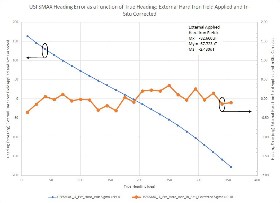
![]()
The applied hard iron offsets estimated from the spherical fit were Mx = 82.660uT, My = -67.723uT and Mz = -2.430uT. These components are actually quite large, as the geomagnetic field is nominally ~50uT. The blue curve (Left-hand axis) shows the heading error of the uncorrected USFSMAX motion co-processor AHRS solution under the influence of the applied hard iron offsets. The hard iron interference is so bad that the indicated heading is nearly constant, only ranging between 141.5 and 167.1 degrees in a full 360 degree rotation. The corresponding RMS heading error was 99.4 degrees. The bold orange curve (Right-hand axis) shows the simulated corrected AHRS solution generated simultaneously on the host MCU. The RMS heading accuracy recovered to 0.18 degrees, essentially identical to the immediate post-calibration value.
I believe this is an important result. This real-time, in-situ method of fitting a sphere to the (Mx, My, Mz) data ensemble allows us to neutralize the degradation in heading accuracy performance that often occurs between calibration on the test bench and deployment out in the field. My next step will be to program this analytic sphere fitting method and associated infrastructure into the USFSMAX standard firmware. There will be a significant amount of experimentation required to learn how to best manage/filter which points are included into the sphere-fitting (Mx, My, Mz) data ensemble... And when to clear the data buffers and start over. But these initial results show there is a straightforward path to follow.
-
MAX32660 Motion Coprocessor - Initial Results
11/27/2019 at 00:29 • 5 commentsSensor Calibration and Performance Testing
Calibration
Many people seem to think that good orientation estimation results are primarily due to some "Special sauce" contained in the sensor fusion algorithm. In fact, few consider there to be any significant differences between the various MEMS sensor products offered by different manufacturers. The reality of it is that there is no such thing as an algorithm that can correct poor quality accelerometer, gyroscope and magnetometer data to give excellent orientation estimation results. We have shown that once the non-ideal behavior of the accelerometers and magnetometers have been neutralized through effective sensor calibration, any effect of the particular fusion algorithm on orientation estimation accuracy is secondary. Consequently, in the development of the MAX32660 motion co-processor I focused on making firmware infrastructure that can:
- Perform sophisticated sensor calibrations using embedded routines and store the results in the co-processor
- Reduce run-time implementation of the various sensor calibrations to simple, calculationally efficient forms
The need to embed complicated calibration functions and perform a significant volume of additional floating point calculations figured prominently into the selection of the MAX32660 for an advanced motion co-processor; it has a lot of memory and floating point processor power in a small package.
A short discussion of what constitutes effective accelerometer and magnetometer calibration would be helpful at this point. We will consider the magnetometers first. For a perfectly calibrated three-axis magnetometer, the Mx, My, Mz response surface is a perfect sphere centered at the origin. "Hard iron" errors occur when there is a static magnetic field in the magnetometer's reference frame that displaces the response surface from the origin by a constant vector. "Soft iron" errors result from magnetic flux divergence and are manifested as the response surface being distorted from a sphere to an ellipsoid. Both types of error can be corrected by fitting an ellipsoidal surface to uncorrected 3D magnetometer data and then transforming back to a sphere with no offset vector. Freescale Semiconductor (now NXP) published a good C library to fit the uncorrected magnetometer data and generate both soft and hard iron calibration corrections. This library is included in the "MotionCal" application distributed by Paul Stoffregen of PJRC. I started with the code in Paul Stoffregen's GitHub repository and re-cast Freescale's solver for embedding into the motion co-processor. This works quite well and consistently results in residual fit errors of <= 1.5%.
Effective accelerometer calibration is also essential to achieve accurate estimates for heading, as well as pitch and roll. There are numerous methods for correcting accelerometer imperfections including:
- Bias (zero-point offset)
- Scale error
- Non-orthonormality of the x, y, z sense axes
Of all the potential accelerometer calibration techniques in the literature, the "Tumble" method seemed the most suitable for the purposes at hand. By collecting raw ax, ay, az data in a number of orthogonal orientations, the accelerometer errors listed above can be quantified and calibration corrections accurately estimated.
The final category of sensor non-ideality that needs to be addressed is relative rotation between magnetometer and the accelerometer (inertial) sense axes. This turns out to be important because the pitch and roll angle estimates are derived from the 3D accelerometer data. Pitch and roll are used to resolve the 3D magnetometer components from the sensor reference (body) frame into the horizontal plane of the world reference frame for heading estimation. This is true for quaternion-based fusion filters as well as explicit direction cosine rotation-matrix-based projections of the magnetic field vector. Fundamentally, relative rotation of the inertial and magnetometer sense axes corrupts the "Tilt compensation" of the magnetometer, increasing the heading-dependent heading error.
I did a fairly extensive review of the literature and determined that there was a simple version of the accelerometer tumble calibration method presented in this reference. Specifically, the accelerometer calibration is performed by enclosing the sensor board in a fixture with six orthonormal surfaces and collecting data with the normal vector of each face parallel to gravity. The essential outcome of this method is that the correction offsets and 3x3 correction matrix effectively align the inertial axes parallel to the face normal vectors of the calibration fixture. By extending the technique to 24 positions, it is possible to simultaneously align the magnetometer sense axes to the calibration fixture face normal vectors as well... Effectively aligning the magnetometer and inertial sense axes to each other.
Weighing all of these factors carefully, the sensor calibration strategy I selected to program into the MAX32660 motion co-processor includes:
- Gyroscope bias estimation (startup, board at rest in any orientation)
- Subtract biases from each data point at run time
- Embedded Freescale ellipsoidal magnetometer calibration (manually rotate board randomly in 3-space)
- Collect raw magnetometer data during calibration
- Subtract biases from and apply 3x3 correction matrix to each magnetometer 3D data point at run time
- Enhanced 24-point "Tumble" calibration (align board using orthonormal calibration fixture)
- Apply ellipsoidal calibration corrections to 3D magnetometer data during calibration data collection
- Collect raw accelerometer data during calibration
- Apply magnetometer offsets and 3x3 correction matrix "On top of" the ellipsoidal calibration corrections at run time
- Subtract biases from and apply 3x3 correction matrix to each accelerometer data point at run time
Performance Testing
I measured heading accuracy using a precision three-axis goniometer to accurately align the motion co-processor board and provide the "Ground truth" orientation. The specific instruments and fixtures I built for the 24-point tumble calibration and motion co-processor characterization will be the subject of an upcoming Hackaday project.
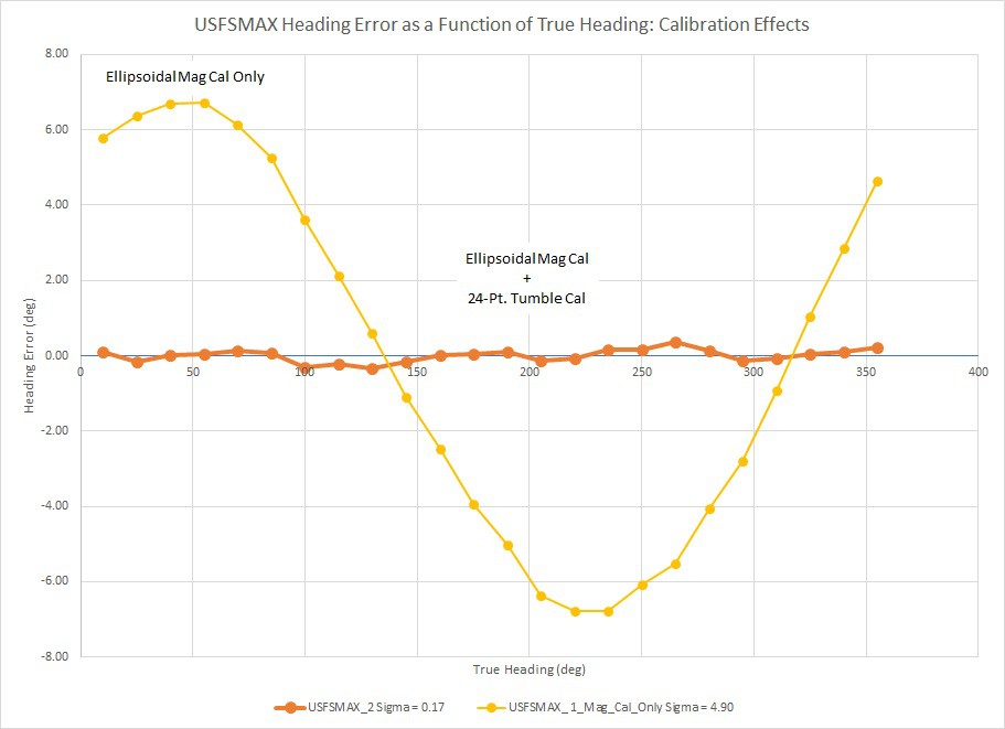
Initially, I aligned the motion co-processor board level to the goniometer stage using a precision spirit level and measured heading accuracy at pitch = roll = 0deg (level attitude). The figure below shows the individual effect of the ellipsoidal magnetometer calibration on heading error and the overall effect when followed by the 24-point tumble calibration. The deviation of the indicated heading from the actual heading (imposed by the goniometer) is plotted as a function of the actual heading. The heading error curve for the "Ellipsoidal Mag Cal Only" case is strikingly sinusoidal with a period of 360deg. This is characteristic of uncompensated hard iron error, magnetometer tilt correction error or both.
![]()
Since the ellipsoidal magnetometer calibration is effective at removing hard iron biases and uncalibrated accelerometers will certainly induce pitch and roll estimation errors, tilt correction error is much more likely. Application of the 24-point tumble calibration after the ellipsoidal calibration (bold curve) totally neutralizes the residual sinusoidal heading error. This strongly suggests that indeed the +/- ~6deg sinusoidal heading error is due to erroneous tilt correction from relative rotation between the magnetic sense and inertial axes. The 24-point tumble calibration effectively aligns the magnetometer and accelerometer responses and the 360deg-period heading error goes away.
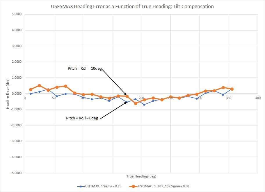
To further verify this assertion, I imposed tilts of pitch = roll = 10deg and re-measured the heading error.
![]()
We typically use the root-mean-square (RMS) of the heading error as a figure of merit for comparing various attitude estimation solutions. In this case, the RMS heading error at level attitude is 0.25deg. After imposing a resolved tilt of ~14.4deg (bold curve), the RMS heading error was 0.3deg, basically unchanged. So not only does the 24-point tumble calibration address the large residual sinusoidal error at level attitude, the results hold up at a significant tilt. From this I conclude that the calibration regimen programmed into the MAX32660 motion co-processor effectively addresses hard iron error, soft iron error and magnetometer tilt compensation.
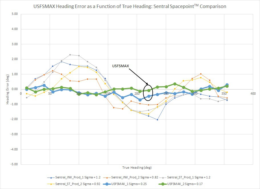
Finally, I performed the full calibration regimen (from "scratch") on a MAX32660 motion co-processor board and measured the heading error twice at level attitude. The results (bold curves) are plotted with those from four different production USFS motion co-processor boards using the EM7180 "Sentral" sensor fusion hub.
![]()
All measurements were conducted under identical conditions using the same three-axis goniometer instrument. The RMS heading error for the USFSMAX motion co-processor was 0.17 - 0.25deg while the Sentral ranged between 0.92 and 1.2deg. It is also interesting to note that the Sentral heading error is sinusoidal in nature with a period of 180deg. This is characteristic of uncompensated soft iron error. Based upon these results, I conclude that the Sentral's heading accuracy is limited by the on-board dynamic calibration algorithm's ability to compensate soft iron effects... And that my calibration methods addresses this weakness.
The results presented in this log are based upon hand-built prototype boards. Kris is in the process of having a small production run of the MAX32660 motion co-processor boards made at a professional manufacturer. When these are complete, my next step will be to randomly select a sample of units and repeat the same calibrate-and-measure procedure to estimate baseline unit-to-unit variation of the heading accuracy...
-
Final Hardware Design
11/19/2019 at 01:01 • 0 commentsNovember 18, 2019
As Greg mentioned in his log, we are making good progress on the motion co-processor firmware. We are also getting ready for pilot production of the hardware next month and are considering options for the 0.5 x 0.7 in. product board.
The baseline is the same design we have been using for testing, more or less.
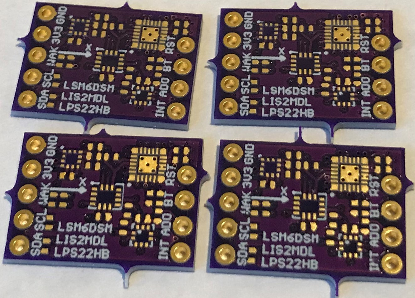
![]()
Baseline MAX32660 motion co-processor design pcbs from OSH Park
This design uses the 0.4-mm-pitch, 3 mm x 3 mm MAX32660GTG+ TQFN-24 package (without bootloader) and the LSM6DSM, LIS2MDL, and LPS22HB (10 DoF) sensor suite. We have dropped the 32.768 kHz crystal, since this is only needed if the MAX32660 RTC is required, which it is not in this application. We have also added a bypass capacitor to nRST that eliminates spurious device resets (good practice in any case). We have added 10K pulldowns to the formerly SWD port, one for an I2C address pin and one to put the MAX 32660 into boot mode, which returns these two pins to an SWD port for reprogramming.
The advantage of this design is the inexpensive manufacturing using OSH Park design rules (for 4-layer pcbs). This makes it possible for anyone to easily customize this open-source design for their applications as well as reduce the per-board cost of manufacturing. The disadvantage is the "large" size of the MAX32660 package. This makes it necessary (for this board size) to drop one of the plated through holes, which will complicate mounting onto popular development boards like the Teensy or Dragonfly but should pose no problem for breadboard use.
The alternative design uses the 0.35-mm-pitch, 1.6 mm x 1.6 mm MAX32660GWE+ WLP-16 "flip chip" package (without bootloader).
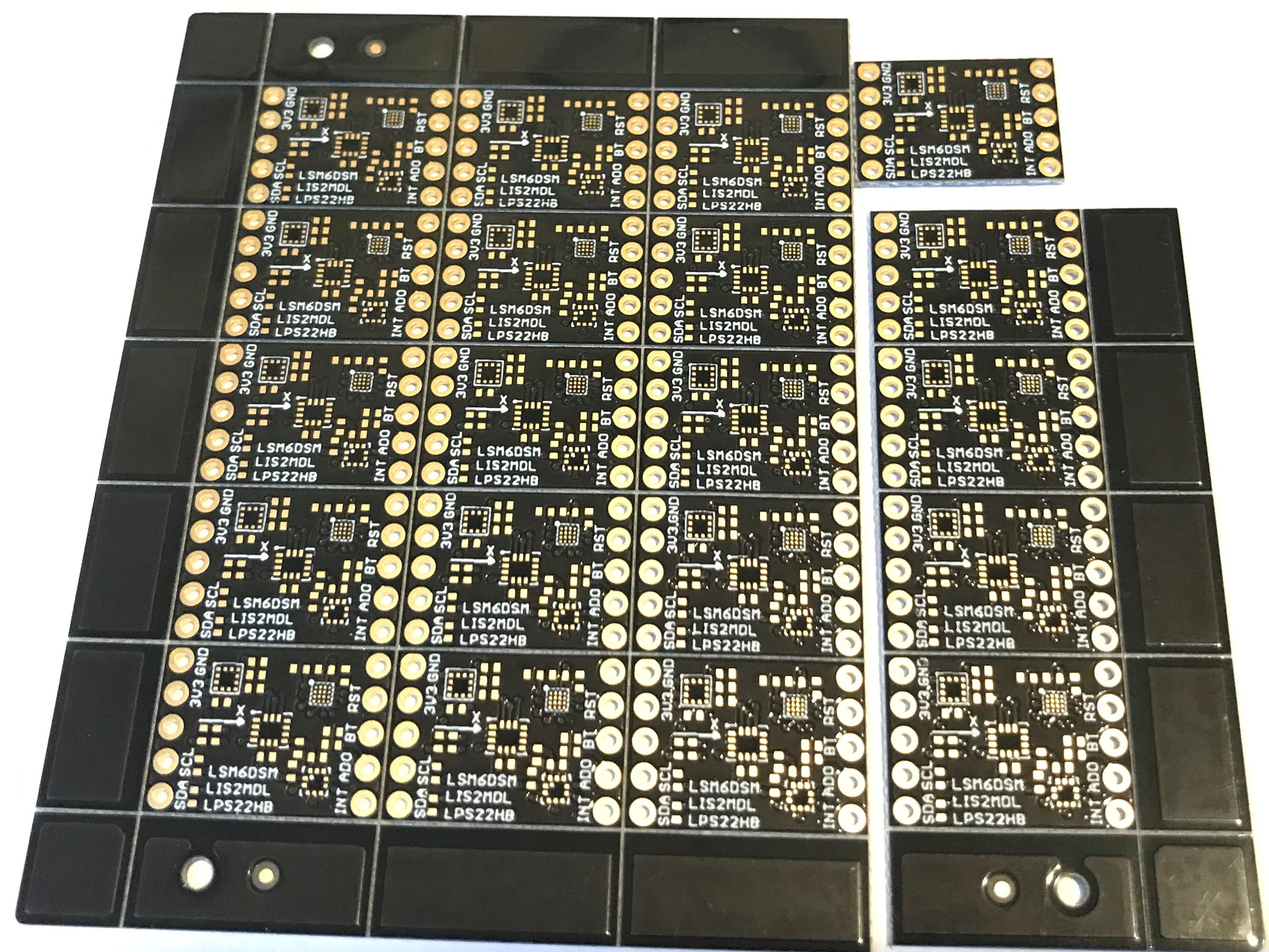
![]()
Twenty-board panel from Sunking Circuits.
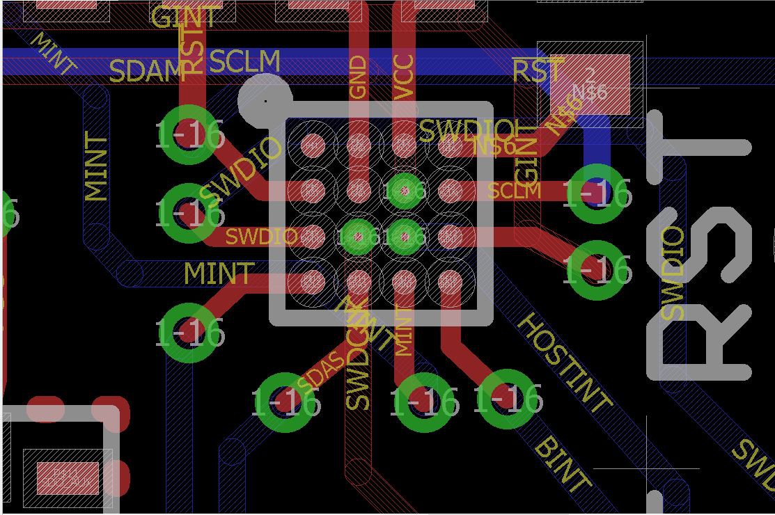
All 16 of the pins are required for the design including the four internal pins; one is connected to GND and three are connected to SDAM, SWCLK, and host INT. I used EAGLE CAD to design this version and had to violate OSH Park design rules in order to place 3 mil vias onto these three internal pins:
![]()
This would never work since the via annuli are too close together. This is an especially difficult part to design with since the pitch is 0.35 mm and the pads are 0.18 mm in diameter, both 10-15% smaller than most other WLCSPs I have dealt with, including the EM7180. Fortunately, I found a cooperative fab house (Sunking Circuits Electronic LTD) who took the design and modified it to conform to their via-in-pad process:
![]()
Board layout of the pin pads after rework by Sunking.
According to Sunking "there will be solder mask covering the three rings of the resin plugged vias, the yellow parts will be the exposed pads, their final diameter will be 0.18 mm with a tolerance of +/- 20%."
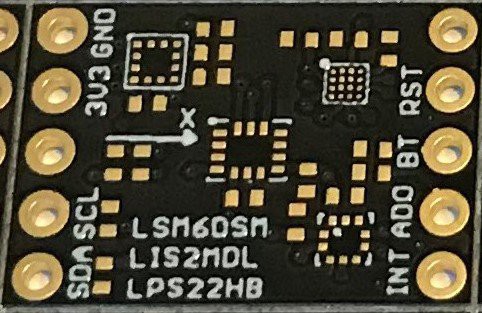
The first batch had to be scrapped because of some kind of debris in the production process, but I just received the second "good" batch which passed their internal testing and look marvelous:
![]()
Close up of the second design option.
The cost was ~$16 per board for 20 of them delivered including the $200 NRE for setup on every new pcb design, high by OSH Park standards but not prohibitive. And certainly much cheaper than I could have had this work done locally in Silicon Valley. This means that if I produce 100 of these at Sunking the pcb cost would likely be about ~$5 per board instead of the ~$1 per board the baseline design might cost.
So this extra cost and the added complexity of the production are definitely a disadvantage. The advantage is that we get back the missing PTH at the board corner, and maybe a cleaner design. Not sure it is worth it. But this was a useful learning experience in that there are many 0.4-mm-pitch WLSCP devices that I would like to be able to use that are now within range of my design abilities and pocketbook.
The next challenge is assembling one or two of these boards and testing them for function. We'll post some comparative testing results in a future log soon.
I am sure we will go to pilot production with the baseline, and I might have 100 of the WLCSP design made just for the fun of it. I expect these MAX32660 motion co-processor boards, which we are calling the USFS-MAX (Ultimate Sensor Fusion Solution) to be for sale on Tindie in January.
Update: Just placed the order for the 100 unit pilot production of the baseline design, which should be delivered for testing by the end of December. Assuming the boards work as expected, these will go on sale at Tindie in January.
-
MAX32660 Motion Co-processor Firmware Development Challenges
11/17/2019 at 02:33 • 3 commentsWell, it has been a long while since any log entries have been posted for this project... That is not because Kris and I haven't been working on it but because there have been some serious software development challenges to overcome. It is one thing to try out some of the simple I2C loop-back examples in Maxim's software development kit (SDK) or blink an LED but it is a fundamentally harder task to make the MAX32660's peripherals perform to the level required by a high-speed asynchronous sensor fusion engine.
I'm happy to report that the "show-stopper" software infrastructure problems preventing a robust, high-performance motion co-processor implementation on the MAX32660 have been solved. We have demonstrated reliable operation and excellent attitude estimation results from MAX32660-based parts. I plan to open a new project to document general motion co-processor calibration/characterization instrumentation and procedures soon. Results from the MAX32660 motion co-processor will figure prominently into this effort. The remainder of this log entry will be an overview of the firmware development challenges and what it took to overcome them.
When I set out to write motion co-processor firmware for this micro-controller, I already had almost all of the necessary algorithmic and calibration "pieces" in-hand and successfully implemented on other micro-controllers. This should be the hard part, right? Not so fast... There are some other basic pieces of "data plumbing" that are absolutely essential to make a motion co-processor work on any micro-controller:
- An EEPROM emulator to store co-processor configuration information and sensor calibration data for retrieval at startup
- An asynchronous I2C master bus; sensor data ready (DRDY) interrupts initiate an I2C data read transaction from the appropriate sensor with a completion callback to the main sensor fusion loop
- An asynchronous I2C slave bus; the host micro-controller (connected to the MAX32660) must be able to query the co-processor for data and receive a prompt response without significantly delaying the main sensor fusion loop
- Rising-edge-interrupt-capable GPIO pins to handle sensor DRDY interrupts.
After an initial assessment of Maxim's SDK, it became clear that only the rising-edge interrupt capability would be straightforward. I addressed the other three items in this order:
- EEPROM emulator
- Asynchronous I2C master bus
- Asynchronous I2C slave bus
I should say that if any one of these capabilities could not be successfully implemented on the MAX32660, completion of the project would not be worthwhile. The final product would simply not be competitive. Before I proceed much further, I want to acknowledge the fact that I was very lucky to have an excellent teacher/mentor along the way. Thomas Roell is truly a master at micro-controller application programming interface (API) development and he shared his expertise with me generously. Without his inputs and help along the way it would have certainly been much, much harder to bring the project along this far.
EEPROM Emulator
An EEPROM capability is crucial for a motion co-processor. The basic proposition here is that we are using economical MEMS sensors as the inputs into the fusion/attitude estimation algorithm. No matter what, there is no algorithm that compensates for bad sensor data... So good sensor calibration is a prerequisite to achieve an accurate attitude estimate. Since MEMS sensors can significantly depart from ideal behavior, effective calibration may require more involved procedures performed under controlled conditions. The calibration procedures generate parametric corrections that are applied at run-time. If the sensor calibration procedure(s) are impractical to do each time at startup, the sensor correction parameters need to be available in non-volatile memory (NVM).
The basic idea behind an EEPROM emulator is that part of the micro-controller's flash memory is set up to mimic a writable ROM without the user having to do any of the hard work of following the flash memory's rules for locking, unlocking, reading, writing and erasure. Furthermore, the EEPROM emulator manages usage of the underlying flash memory to prevent premature wear-out of any individual flash memory bits. It turned out to be fairly easy to develop an EEPROM emulator for the MAX32660... Largely because Thomas Roell had already written a good EEPROM emulator for the STM32L4, another Cortex M4F micro-controller. The basic emulator algorithm was copied from the STM32L4 and only the MAX32660-specific flash read/write/erase/lock/unlock commands needed to be updated.
Asynchronous I2C Master Bus
I took a long look at the I2C master bus asynchronous API supplied in the MAX32660 API and realized that the way it was written had a serious flaw: It only does a single read or write unit transaction per function call. However, an I2C master read is actually two unit transactions: 1) Write the data register address from the master to the sensor, 2) Read data bytes from the sensor (starting at the data register address just written) to the master. The problem here is that the data callback from the first instance of the async I2C transfer function (to write the starting data register byte) has to call the same async transfer function again to read the data bytes from the sensor. Why is this a problem? Unless you are very careful:
- The bus is released in between the sensor data register write and the sensor data read, killing the read transaction
- Multiple instances of the async I2C transfer function may be left open, causing concurrence issues and/or the stack running out of memory space
After a great deal of User's Guide spelunking and logic analyzer experimentation, I re-wrote the I2C API so that both master read and master write transactions can be done with a single call of the I2C async transfer function and no recursion. This was accomplished by making all cases in the transfer function fully driven by I2C controller hardware interrupts.
Fixing the async I2C master bus API was a big step forward but there was still another huge problem to be solved: concurrent I2C transactions (because there are multiple sensors on the MAX32660's master bus). Fortunately, Thomas Roell already mapped out a good solution for this on other Cortex M4F micro-controllers:
- Write void-type wrapper functions for the I2C data read functions associated with each sensor
- Declare pointer variables for each sensor data read wrapper function
- Declare a Boolean status variable to indicate when the master I2C bus is busy
- Make a read function pointer ring buffer; every time there is a sensor DRDY interrupt, enqueue the appropriate data read function pointer into the ring buffer
- Service the read function pointer ring buffer regularly; if the I2C master bus isn't busy with a transaction, set up the next sensor data read transaction to be executed by the Cortex "PendSV" handler
After working through the actual coding of this method, the results were gratifying. It is possible to asynchronously burst-read the accelerometer, gyroscope, magnetometer and barometer data without causing any significant timing fluctuation of the main co-processor loop. This solution runs robustly at I2C clock speeds up to 1MHz and should be readily expandable to include auxiliary sensors in the future. The current LPS22HB baro sensor doesn't work at 3.4MHz I2C clock speed... But there seems to be no fundamental reason why the I2C master bus can't run at 3.4MHz so long as all of the sensors on the bus can support the higher clock speed.
Asynchronous I2C Slave Bus
The slave bus turned out to be a larger challenge than anticipated but for very different reasons than the I2C master bus. Again, the async slave bus API included in Maxim's SDK is implemented as a transfer function that is called for each unit I2C transaction. This is just like the original master bus API... It turns out that it is a poor approach for an I2C slave bus. Despite this shortcoming I tried to make Maxim's I2C slave bus API work anyway. I was successful but only for 100kHz I2C clock frequency. At higher clock speeds the slave bus would freeze within a few transactions. The logic analyzer showed that during a master read:
- The host successfully writes the data register address and the MAX32660 would acknowledge (ACK) this byte
- However, the MAX32660's I2C controller hardware ACKs the data register byte while the main processor prepares the data to be read by the master. These are independent parallel processes
- So there is a race condition here; if the MAX32660's processor is late preparing the data to transfer, the data register byte ACK is missed while the master read transfer is being set up... And no data is loaded into the slave bus transmit buffer
- When this happens, the MAX32660 transmits no data to the host micro-controller while the host stretches the I2C clock indefinitely
When the I2C slave bus clock was running at 100kHz, there was enough time to prepare the data and set up the master read transfer before the MAX32660's I2C controller ACK'd the data register byte coming from the master. At 400kHz clock speed, not so much... This was a disappointing outcome because a 100kHz I2C slave bus can't deliver sensor and orientation estimate data to the host micro-controller at the desired 1kHz update frequency; the I2C transfer time overhead is too great.
The solution was a complete re-write of the I2C async slave API:
- There is only one function call to set up the MAX32660's I2C slave bus peripheral controller
- All slave bus transactions are driven by peripheral controller hardware interrupts
- A single interrupt service request (ISR) handler manages all of the peripheral controller interrupts
- The race condition described above is eliminated by delaying the ACK to the data register byte until the MAX32660 is ready to supply the necessary data for the master read transaction
This approach has yielded far superior results. The slave bus runs robustly at 1MHz clock speeds. The data transfer rates to the host micro-controller are more than sufficient to support 1kHz accelerometer, gyroscope and attitude estimation update frequencies...
-
Some Power Measurements
08/25/2018 at 01:15 • 5 commentsAugust 24, 2018
First some housekeeping. I learned from Maxim that there was a typo in their data sheet (since corrected) and that the MAX32660 roadmap only includes three device packages: the 1.6 mm x 1.6 mm WLCSP-16, the 4 mm x 4 mm TQFN-20, and the 3 mm x 3 mm TQFN-24 that we are using in our prototype development. No 1.6 mm x 1.6 mm TQFN-16 package :< We will have to make do with the 3 mm x 3 mm version or bite the bullet and go for more expensive fab methods (or zGlue) and use the WLCSP for minimal size. For the moment we will stick with the 3 mm x 3 mm TQFN-24 IC since it is easy to assemble and has lots of pins for firmware development work.
I have heard that a revision to this TQFN-20 package is due in a month or so that corrects/improves the silicon. Still trying to find out more details but the changes should include improvements in power usage. That is what I want to discuss now.
I finally (with Maxim's help) figured out the low power sector of the MAX32660 and have started doing some preliminary power testing. The low power scheme is a bit different from the STM32L4. There are three core voltages that can be selected which are equivalent to setting the high-speed clock to 96 MHz (OVR= 1.1 V, default), 48 MHz (OVR = 1.0 V), or 24 MHz (OVR = 0.9 V). The actual voltage is an allowed range and lowering this range effectively selects a lower clock speed. Then, for each range the clock can be further divided by 2^N where N can range from 0 to 7. It sounds complicated but in fact it is straightforward to select amongst these limited choices and the effect on average power usage can be quite large. For example, with a simple blink program at 96MHz (OVR = 1.1 V) default the MAX32660 uses 11.1 mA (when the led is off but MCU active). At the lowest core voltage setting (OVR = 0.9 V, 24 MHz) the blink program uses 5.1 mA when using low power sleep mode between RTC alarm interrupts. Let me explain this...
The way most programs we will be using work is to configure everything at the start of the program (like setup in Arduino) and then run a forever loop where all actions are interrupt driven (sensor data ready interrupts, timer interrupts, RTC alarm interrupts, etc). This is so when an interrupt is not being serviced, the MCU can sleep in a low-power state.
So for the simple blink program, we set the RTC alarm to trigger an interrupt every two seconds. The interrupt wakes the MAX32660, it takes some action (turns the led on or turns the led off) and then goes back into SLEEP mode. The program uses 11.1 mA at 96 MHz without invoking SLEEP mode between interrupts and 9.6 mA when SLEEPing between interrupts. The average power drops to 5.1 mA when running at 24 MHz with SLEEP between interrupts. This demonstrates the benefit of the SLEEP scheme as well as selecting the clock speed appropriate to the task, and it just makes common sense to take advantage of these features as a general strategy.
The wake up time from SLEEP mode is very fast (a few us). There is also a DEEPSLEEP mode with a somewhat longer wakeup time (~1 ms), and using this instead of SLEEP at 24 MHz (OVR = 0.9 V) drops the average power down to 175 uA. About 6 uA of this is just due to the sensors in power down mode on the custom board. This (~169 uA) sounds like an impressive power savings and it is much lower than 5.1 mA, but the data sheet says we should be at ~4 uA. So some more fine tuning is required like turning off peripherals that aren't needed (like SWD) and making sure all GPIOs not being specifically used are tri-stated, etc. to get the power as low as possible.
Also, the pending silicon revision should reduce this 1 ms wake up time considerably. Still lots of work to do to get the power sector under control. The goal is 1 mA or less when running the motion co-processor in its normal mode, meaning accel and gyro at 208 Hz, mag at 100 Hz, and barometer at 10 Hz with quaternions at the rate of the gyro.
The EM7180 uses ~300 uA on average and the ST sensors 650 uA under these conditions so we want to be able to run the MAX32660 with this same level of power usage and still produce high-accuracy absolute orientation estimates (<1 degree rms heading error). Of course, the MAX32660 can run at much faster fusion rates than the EM7180, but it needs to be able to run at the same or lower average power usage. This is the twin challenge that we expect our continuing development efforts to meet.
Preliminary testing using SLEEP mode between interrupts shows the MAX32660 plus ST sensors at the above conditions with the Madgwick fusion algorithm uses about 4.3 mA at 24 MHz (OVR = 0.9 V). Until the silicon revision, it is not clear it is advisable or even possible to run at such sample rates with a 1 ms delay (wake up time) between active and DEEPSLEEP modes. Edit: did it anyway, got DEEPSLEEP to work with the ST sensors and measure 3.3 mA average current at 24 MHz, so better but a lot more work to do...
So we are far from our power usage goal, but these are still early days...what fun!
-
First Successful Programming of MAX32660
08/14/2018 at 01:29 • 7 commentsAugust 13, 2018
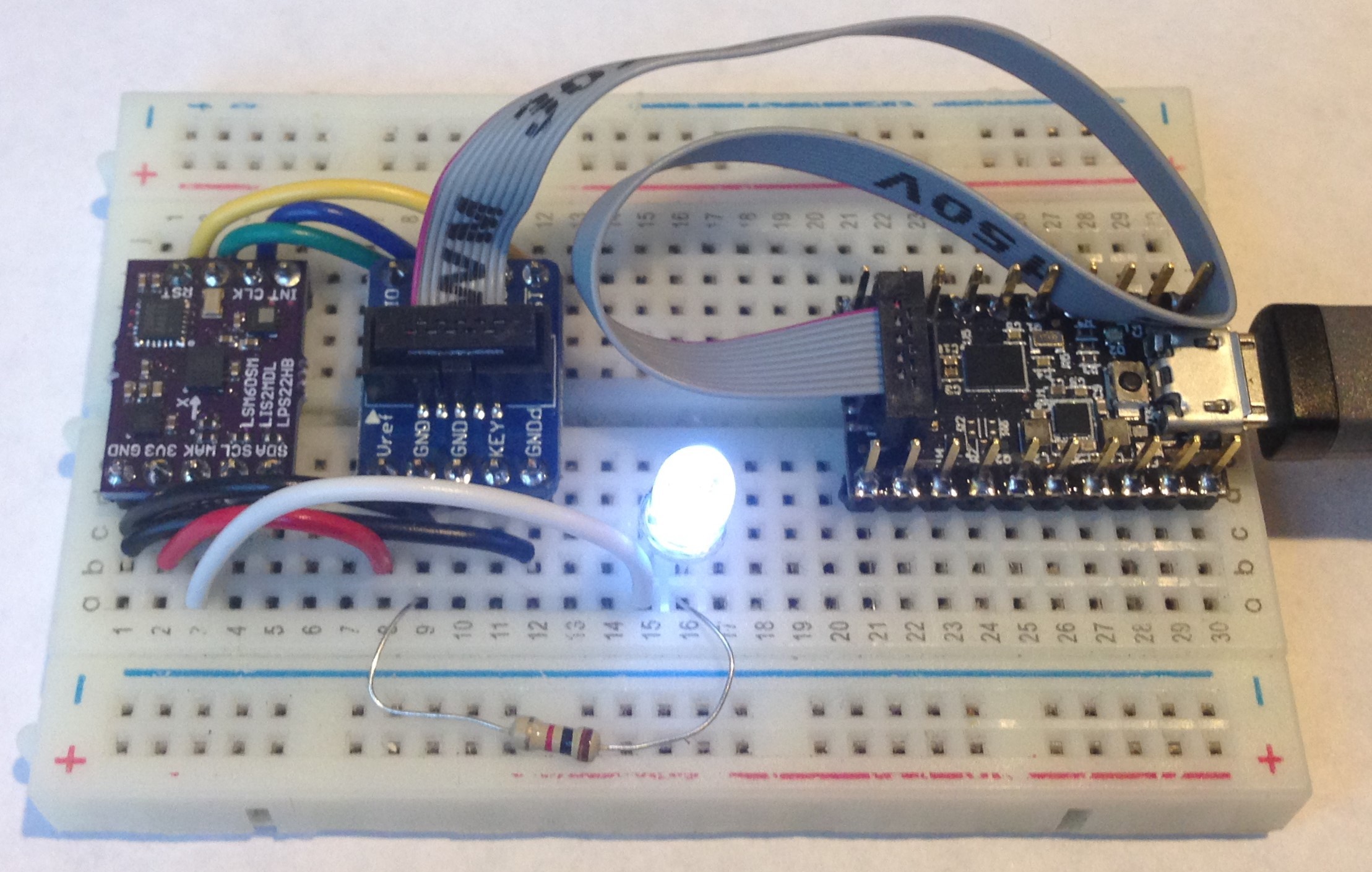
As soon as we tried to program our custom MAX32660 motion co-processor board we knew we had a problem. The MAX32625 PICO DAP debugger which came with the MAX32660 evaluation kit and the MAX32625 PICO debugger we bought separately both interface with the MAX32660 target via a 2 x 5 SWD 0.05-inch connector, which of course, we didn't put on our tiny 0.7-inch x 0.5 inch breakout board; no room! We did expose SWDIO and SWDCLK as well as nRST on the breakout board edges. That is, we expected to have to use the SWD port to program our breakout. We just didn't think it would be so hard to do so.
First we tried to use the edge pins on the MAX32625 debugger which are supposed to connect to SWD and nRST, etc but we couldn't make this work. Not sure why. Programming via the SWD connector did work on the evaluation board so we ordered some SWD cable breakout boards from Adafruit (faster than making our own), which allowed access to all of the SWD signals from the 0.05 inch cable. And...success! Simply connecting SWDIO, SWDCLK, GND, nRST, and VREF to 3V3 and we were able to program the custom board MAX32660 to toggle one of the GPIOs we exposed as WAKE on our breakout. The toggled GPIO then actuates an led and voila:
![]()
Here we have GND_detect also connected but we subsequently learned this is not needed.
Yes, it is a little clunky but for prototype hardware and firmware development this works just fine. In the end-user application, once programmed with firmware the breakout doesn't need to be programmed again. The breakout will communicate with the host MCU via I2C in use. So in reality for the final product we don't need SWD and nRST exposed to the user; and it is a shame to waste valuable board edge just for one-time programming. So we will likely expose the SWDIO/SWDCLK, and nRST along with GND and 3V3 as a 2 x 3 test pad pattern on the back of the board that can be programmed at the fab using a pogo pin connector.
This was the last technical hurdle to overcome for proof of concept. Now we will continue our firmware development and, in a few days, test the board as a motion co-processor to an STM32L4 host MCU. Very exciting!
MAX32660 Motion Co-Processor
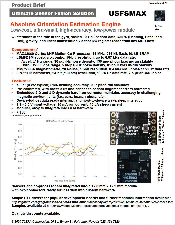
Super-small, ultra-low-power 96 MHz Cortex M4F co-processor manages sensors and processes data allowing the MCU host attend to other things.