Below is the setup code for the A to D converter. The subroutine sets up port A’s inputs RA0 and RA1 for analog and leaves the rest as digital pins. The subroutine also sets the A to D module to allow each input to be individually sampled.

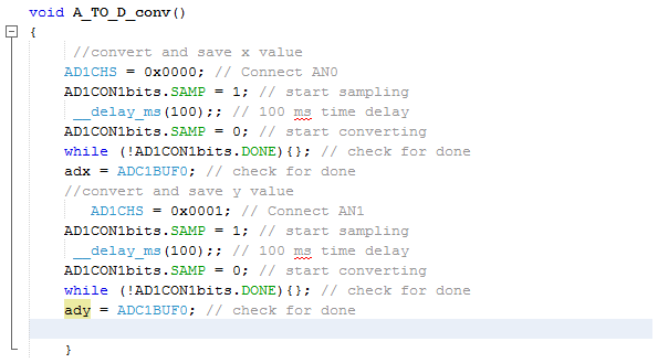
Below is the subroutine to sample and store the analog values for the two potentiometers. The subroutine consists of two sections, one for each potentiometer. The subroutine first sets the address of the input, starts sampling, waits 100ms and starts the conversion. After the conversion is done, all 10 bits of the value is saved in a register which will be used to build a string to send to the robot being controlled.

 Dennis
Discussions
Become a Hackaday.io Member
Create an account to leave a comment. Already have an account? Log In.