-
1Download Arduino IDE
Before starting with building anything you should make sure your computer can communicate with the Adalogger M0 board and that you can flash sketches to it. This should reduce frustration later. Start by installing the Arduino IDE.
-
2Install Arduino boards files to let the Arduino IDE flash the Adalogger M0
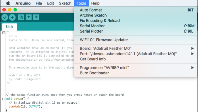
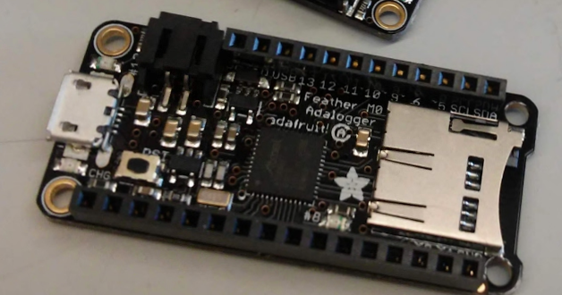
The Adafruit M0 Adalogger board is not natively supported by the Arduino IDE. Follow instructions here to install support for this board in the Arduino IDE. After completing these steps make sure you can flash the example sketch "Blink" to the Adalogger board before continuing. To do this, open the Blink example in File>Examples>Basic>Blink.
"Double-click" the small physical button on the Adalogger board to put it in bootloader mode, set Board to "Adafruit Feather M0" and port to the correct COM port and click upload (the right arrow at the top of the Arduino IDE). You should see "Upload complete" in the bottom feedback window and the red LED on the board should blink once per second.
Congratulations, you have configured your Arduino IDE and uploaded a sketch to the Adalogger!
-
3Install relevant libraries
The Sipper device requires the following libraries:
#include <Adafruit_SSD1306.h>
#include <Wire.h>
#include <RTCZero.h>
#include <SPI.h>
#include <SdFat.h>
#include <Adafruit_GFX.h>
#include <TimeLib.h> //include the Arduino Time library
#include <stdio.h>  // include the C++ standard IO library
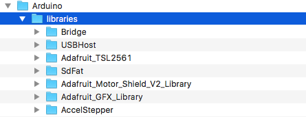
These are available for download as a single zip file from the files area, or you can search for them online. Download the zip file and extract into your Arduino/libraries directory. When you're done it should look something like this:
If this doesn't work, or you'd prefer to install libraries a different way there are instructions here for how to manually add libraries.
-
4Download PIR sketch and compile it in the Arduino IDE
Download and unzip the the Sipper code (also in the files area) to where ever you like to keep Arduino sketches (for me it's: /Documents/Arduino).
Open the code in the Arduino IDE, you should see several tabs across the top. You can check the code out but you don't need to edit anything!
Plug an Adalogger M0 into your computer with a microUSB cable, select the "Adafruit Feather M0" board in Tools>Board, set the correct port in Tools>Port, and finally click the little right-facing arrow in the top left to flash the code to the Adalogger M0.
This will take ~30 seconds, you should see "Upload complete" at the bottom of the IDE if it works correctly. If you see a lot of red error text go back through these instructions and make sure you have the boards and libraries installed correctly.
Nothing will happen on the Adalogger M0 because we haven't built the rest of the electronics yet, but a successful upload confirms that you have all libraries installed correctly and your computer is ready to flash sippers! Congratulations, this is the most common place people run into errors, so if this step works the rest will be easy!
-
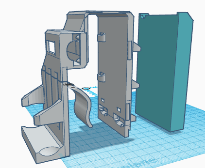
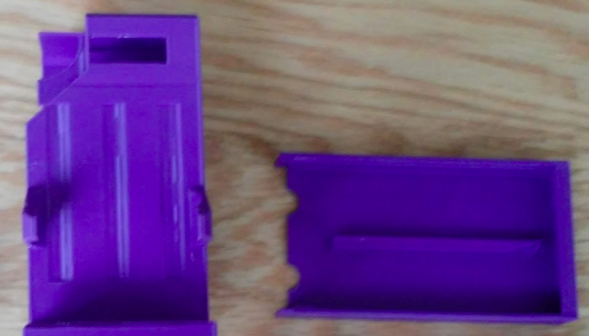
53D print the two 3D parts
-
6Prepare syringes
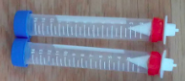
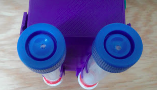
Pull plunger out of 2 syringes and discard. Cut the bottom off the syringes with a razor blade (see photo). Epoxy a valve into the bottom and let dry fully. Drill a small hole in the plastic top. Fill with water and check for leaks.
-
7Put together 2 photo-interrupters
Solder the PI into the Sparkfun breakout board, solder on a 1K resistor (the board says to use a 220Ohm resistor but we found 1K doesn't impair the function of the PI and consumes less power, leading to longer battery life for the device), and solder on the 3 pin JST connector. Be careful with the orientation of the connector, it's important! Plug the wire into this 3 pin jack.
-
8Solder male headers on OLED Feather wing
-
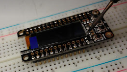
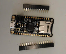
9Solder short female headers onto Adalogger
Solder female headers onto Adalogger board
-
10Solder Photointerrupter wires onto OLED wing
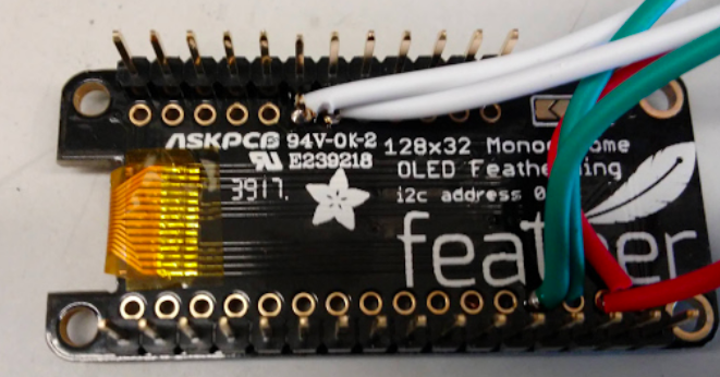
Attach both grounds to the GND pin (4th from right under the word "feather"), both power lines to the 3.3V pin (2nd from right under the word "feather"), and the two signal wires into pin 10 and 11 (6th and 7th from left above the "94V-0K-2" writing). It doesn't matter which is connected to which at this point, you can switch the position of the photointerrupters later.
*** Note, the Sparkfun wires are ~8" long, and we need them to be ~10". You can solder a short extension onto each lead, or purchase these: https://vetco.net/products/jst-ph-connector-male-female-pair-pre-wired-3-pin ***
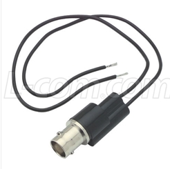
Optional: If you want to synchronize the interactions at each sipper with another piece of equipment, solder one BNC connector to GND (outer wire) and A1 (center wire), and the other between GND and A3. These will report beam breaks at the left and right sippers by pulling the BNC connection high. You can digitize these outputs with a fiber photometry or ephys system. See this log for video of this in action.
Automated mouse homecage two-bottle choice test v2
Version 2: A homecage-fitted apparatus for automated, photobeam-based detection of licks in a two-bottle choice task.
 Meaghan Creed




Discussions
Become a Hackaday.io Member
Create an account to leave a comment. Already have an account? Log In.