-
A simpler ALU (for the Kobold CPU)
04/13/2019 at 08:39 • 0 commentsFor my new project, the KOBOLD Retro TTL computer (that will be a full computer with minimal number of parts), I designed a simpler ALU. For 4 bits, it has only 4 IC's instead of 7. It can also shift right ! It can be found in this Kobold project log.
-
More about subtraction
01/01/2019 at 11:39 • 1 commentThe ALU has an ADD function, that can also be used for subtraction.
Suppose we want to subtract a number A from the number B. We can simply take "minus A" and add it to number B with the adder that we already have.
How do we get "minus A" ? In the 2-complement form that is mostly used, we can make a number negative by inverting all bits, and then add one to the result. But this would need an extra adder just for adding one ! There must be a better way....
To subtract, we can also add the inverted bits of A to B and add the extra one afterwards. But the ADD function has a carry input, When the carry input is high, one is added to the result. So for subtraction, all we have to do is to invert al bits of A, and add it to B while the carry input is high !
How does this work when two 4-bit ALU's are cascaded to form a 8-bit ALU ? Especially, how does the carry signal, that connects both 4-bit ALU's, behave ? As an example I will use two 8-bit numbers A and B, in groups of four bits.
A = 0000 0011  (decimal 3)
B = 0010 1001  (decimal 41)
A is bitwise inverted, producing minus A = 1111 1100
Adding the lowest four bits of minus A to the lowest 4 bits of B, and also adding one because the carry is high for subtracting, we get:
lowest 4 bits: 1100 + 1001 + 1 = 0110 (with Cout=1)
The sum of 1100 and 1001 does not fit in 4 bits, so an output carry is generated ! The output carry is high, and is connected to the carry-in of the next 4 bits. That is convenient, because we already saw that for subtraction, the input carry must be high.
So now the upper 4 bits are added, together with the carry:
upper 4 bits: 1111 + 0010 + 1 = 0010 (with Cout=1).
Total result 0010 0110 (decimal 38). So the result is correct for 41 - 3.
BORROW
In the previous example, the lower 4 bits of A represented the value 3 and the lower 4 bits of B represented the value 9. 3 can be subtracted from 9, there will be no borrow. What if A is bigger than B (for these 4 bits) ? For example:
A = 0000 0101  (decimal 5)
B = 0010 0010  (decimal 34)
Again, A is bitwise inverted, now giving 1111 1010. Adding the lowest 4 bits to the lowest for bits of B and adding one, gives:
lower 4 bits: 1010 + 0010 + 1 = 1101 (with Cout=0).
This time, no carry is generated ! This means, that a borrow has to take place. So now, the upper 4 bits are added without adding one:
upper 4 bits: 1111 + 0010 = 0001 (with Cout=1)
Total result 0001 1101 (decimal 29). The result is correct for 34 - 5.
I hope this will clarify how the subtraction function works !
-
Cascading two 4-bit ALU's
12/08/2018 at 19:00 • 1 commentOf course two ALU 's can be cascaded to get a byte-wide ALU.
But you can get a small gain for the adding speed, when the second nibble is slightly changed.
The following diagram shows the path that the carry signal takes through the adder. The numbers indicate the number of parts that the carry-in signals have to pass in worst case. It can be used to optimize the carry speed.
151 --> 8-input multiplexer for fast carry
153 --> 4-input multiplexer for "normal" carry calculation
86 --> XOR port that produces the final output.

As you see, when both nibbles are equal (left diagram), the output of bit 7 will be the slowest, even slower than the byte-carry output.
The diagram at the right shows that bit7 is now faster. Now bit 6 is the slowest output bit, with 4 delays at the input of its XOR gate.
-
A Relay ALU
11/05/2018 at 09:05 • 1 commentOn the pages of Dieter Mueller you can find a nice Relay ALU with 5 relays. However, this can be improved to the following:
Only 4 relays are used now. The improvement is based on drawing 2 of the carrry generation of the Fast carry circuit described in another log. If you do not want to use diodes, you can instead use a relay contact to disable the carry. Using relays with two contacts, a single relay can disable the carry for two bits.
EDIT oct 2019: I am very proud that this ALU design was used in the RR6 6-bit Reed Relay computer !
[EDIT. An even simpler relay ALU (3 SPDT relays) was designed and presented HERE ]
-
On the Frontpage
10/19/2018 at 06:29 • 0 commentsThis ALU project is on the Hackaday frontpage today, by Brian Cockfield: The math that makes computers go, built on a tiny PCB. Thanks, Brian !
-
Connection and function overview
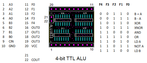
09/24/2018 at 07:50 • 0 commentsA simple overview of connections and functions was not yet given, so here it is:
-
ALU testing
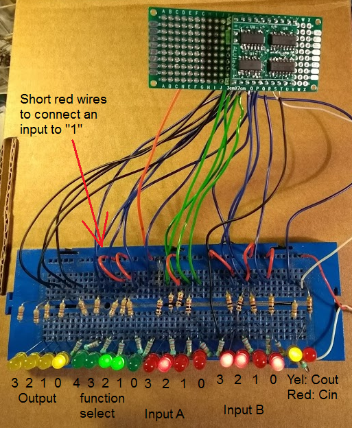
08/31/2018 at 17:08 • 0 commentsA simple test set-up was built to check the ALU. Here it is:
In the picture, the function "ADD" was selected (green LEDs), and the inputs were 0100 and 1101 (on the red LEDs). The output is 0001 (yellow LEDs), and a carry is generated (the yellow LED at the right side). Several functions and input combinations were checked and all were ok.
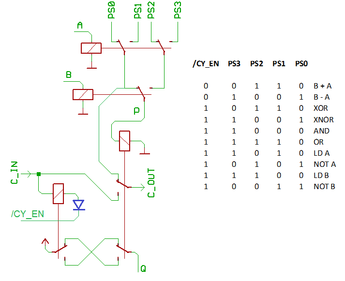
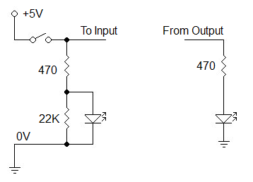
The outputs have LED's, and the inputs have a "switch" (and a LED to check operation of the switch), like this:
The switches are just small red wires on the breadboard that connect an input to "1". Note that the input LEDs have a 22K resistor to define a good "0" level when the switch is open. The red LEDs were very bright, their series resistors were changed to 1K. (This last schematic was drawn with the Klunky schematic editor, an easy-to-use editor for simple circuits, that runs in your browser.)
-
Assembled the ALU
08/30/2018 at 20:04 • 5 commentsYesterday evening the pcb's arrived... I did send the gerbers only 5 days ago to China.... Now here I have 10 pcb's for only 15 Euro, with free shipment... unbelievable....
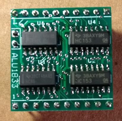
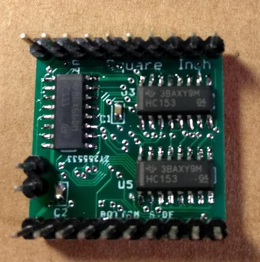
So I assembled one:
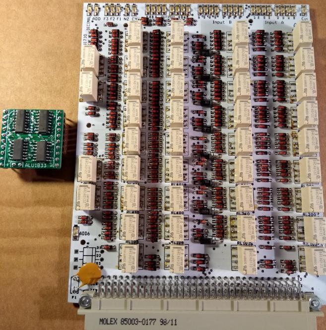
It is nice to see this 4-bit ALU next to the 8-bit relay-ALU from the RISC Relay CPU :
This is not completely fair, because the relay ALU has more functions:
- It is 8 bit wide instead of 4 bit
- It has input registers (latches in this case) for both 8-bit inputs A and B
- It can do addition for binary coded decimals, as well as for straight binary
- It can also do 7-segment encoding
But the Relay ALU can not do subtraction. It can subtract because the registers can deliver inverted bits.
The next step will be, to check or demonstrate the operation of the ALU. I will have to build a small demo setup.
-
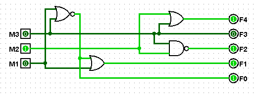
Only 3 control wires
08/24/2018 at 21:00 • 0 commentsI found a way to reduce the control to only 3 wires. It is an extension to the method described in the previous log. The NOT A function was dropped, this can also be done with XOR FF or XNOR 0.
Only four gates are needed. It is based on the observation that the combination M1 = 0 and M3 = 0 was not used. This combination is now detected by the leftmost NOR gate, and this sets the F0 control wire HIGH, and sets the F1 signal HIGH to create the SUB (B-A) and XNOR function.
The XNOR function can be used to check if two values are equal. The XNOR will result in a FF value in this case, and that can be detected by using a 74HC30 (8-input NAND gate, 14 pins). If XOR was used for compare, equality would result in a zero value, and to detect that we would need an 8-input OR gate, that does not exist in a single package (unless the big 74HC688 is used, 20 pins).
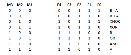
Here is the new function table, sorted according to the 3-bit control value.
The PCB's were ordered today, I hope to have them within 10 days.
-
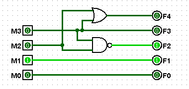
Reduce number of control wires
08/16/2018 at 19:33 • 0 commentsSomeone raised the question if the number of control wires could be reduced from 5 to 4.
Yes, this is possible with a simple external circuit with only 2 gates:
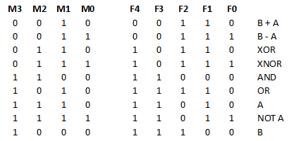
The new control wires are named M0 - M3. This is the new function table:
If one of these 9 functions is dropped, it would be possible to have only 3 control wires. But I don't think the conversion will be as simple as from 5 to 4.
But if the Exor-gates, that can invert the A lines, are removed, then also the M0/F0 control line can be removed, leaving only 3 control lines. The functions B - A, XNOR and NOT A will not be available in that case. But you can still invert a value by XOR'ing with 0xFF.