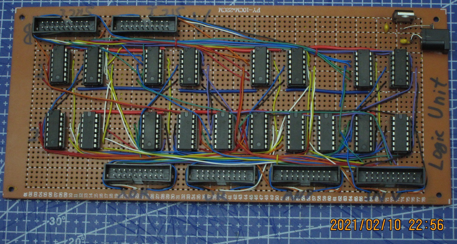
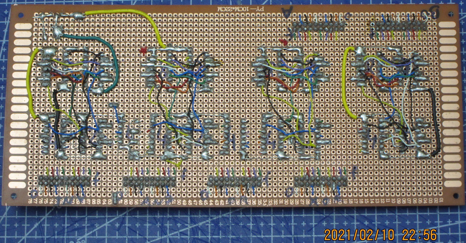
The Logic board for the main ALU is complete. It has two 16-pin inputs and four 16-pin outputs.
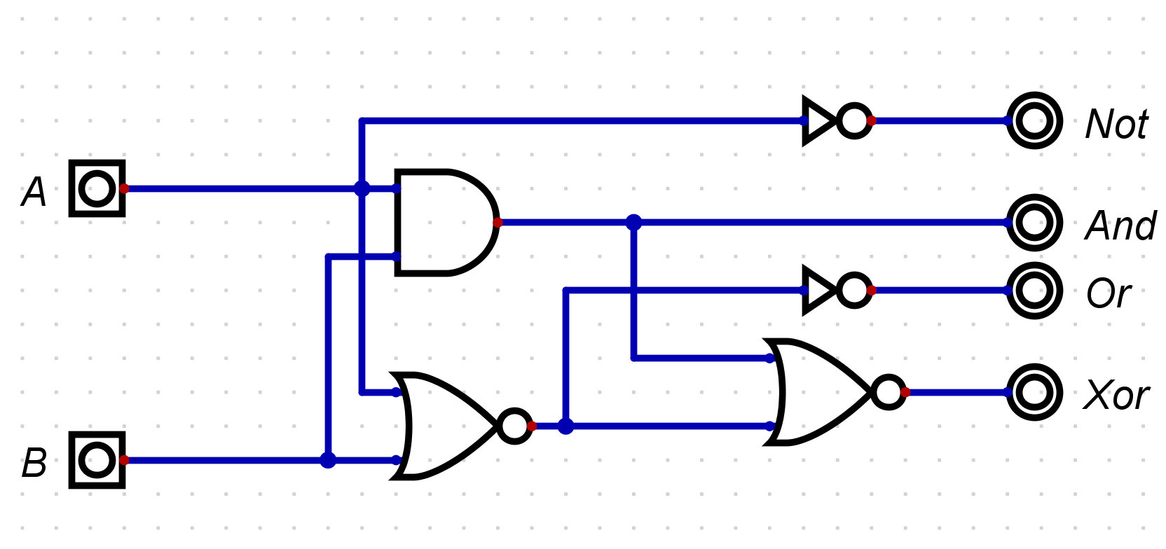
Following operations are performed by the board:
1: AND (A,B);
2: OR (A,B);
3: XOR (A,B);
4: NOT (A);
Inputs and outputs are going through 20-pin IDC connectors, with lines assigned as per following layout:

Ground and Vcc lines are used for powering passive control and indicator boards, for testing purposes. Otherwise these lines are non-functional.
Next are 5 small boards, 2 of them will connect the adder boards and add IDC connector to them, and 3 boards which will be a makeshift control panel to assess the functioning of big boards. The Vcc and Ground lines in connector layout are made specifically to support the little boards.
------------------------------------------------------------------------
This is how the Logic Operations board looks like:


Schematics:

 Pavel
Pavel
Discussions
Become a Hackaday.io Member
Create an account to leave a comment. Already have an account? Log In.