David Prutchi
-
Heading to Supercon and Testing Display Variants
11/02/2018 at 20:24 • 0 commentsWe are on the way to the Hackaday Superconference, and will be bringing the EmotiGlass prototypes. Please feel free to find us during the conference if you'd like to see one or try it out.
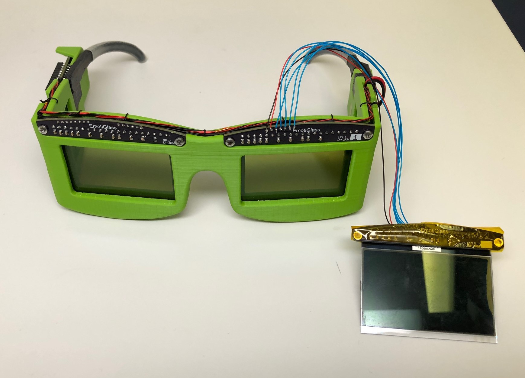
The front LCD displays use modules from the Electronic Assembly DOG series. This line is fairly unique in that the LCD displays and backlights are sold as separate modules, and can then be assembled in the combination suiting the application. For this project, the modular design allows us to easily use only the transparent display portion (with no backlight or reflector) without having to extract it from a complete module. The series we are using, the EA DOGM128x-6, offers the display module in 5 "technology" variants. After eliminating the reflective and colored variants, two options remain.
More details can be found in the datasheet here:
https://www.lcd-module.com/eng/pdf/grafik/dogm128e.pdfThe 'E' variant (DOGM128E-6) is a STN positive transmissive display. Because it is positive, when it is open (pixels off/power off) the display is completely clear. For this reason, we had selected this display to use initially. These displays do have a yellowish tint to them, but it is not noticeable after a few minutes. Because there is a small clear space between the pixels even when they are on (darkened), contrast is limited, and these displays don't block the light quite as well as we would like.
The 'S' variant (DOGM128S-6) is a FSTN negative transmissive display. When off or unpowered, it is dark.
![]()
After building the initial prototypes with the 'E' variant, we decided it would be worthwhile to test the 'S' variant. Initially, we attached an extra display to one of the prototypes and tested it in the clear and dark states. We found that the 'S' variant performs better in the dark state. We had some concern that the dark area between the pixels would be problematic in the clear state, but it's actually less noticeable than the tint from the 'E' variant. Because the 'S' variant works better overall, we changed the displays in one of the prototypes to use them.
This change also require the firmware to be changed to flip everything as the display is now negative. To allow only one firmware version to be maintained, we selected an unused microcontroller pin (A2) and tied it to ground on the prototype that has the 'S' displays. The firmware will be updated to apply the internal pullup to that pin and then check its state, at which point it will know which display variant is installed and can flip everything (or not) accordingly.
-
Complete EmotiGlass Project Whitepaper Uploaded
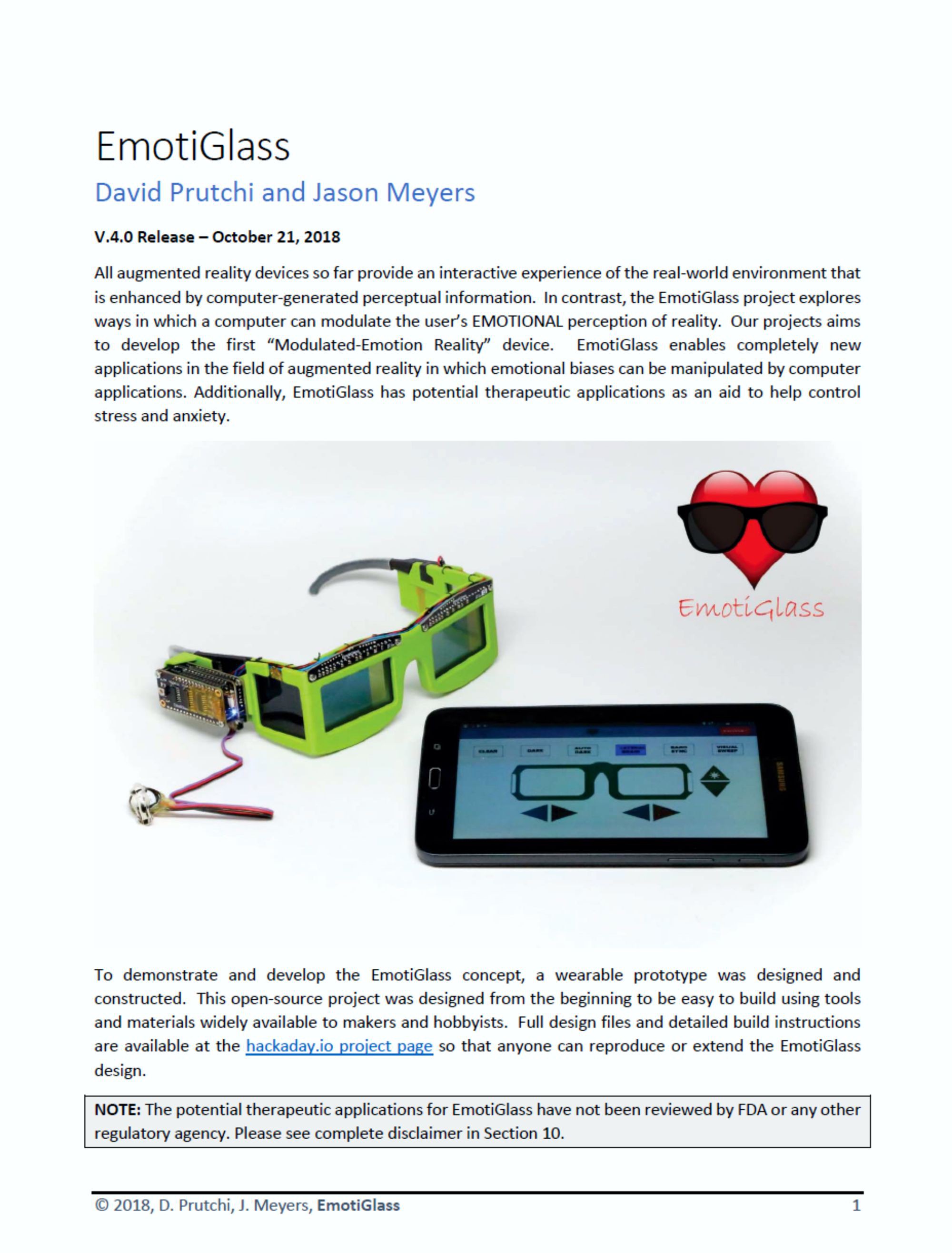
10/21/2018 at 13:10 • 0 commentsA complete writeup for the EmotiGlass Project was uploaded at: https://cdn.hackaday.io/files/1606156871752160/EmotiGlass%20-%20v4.1%20PUBLISHED%20-%20.pdf
This 63-page whitepaper contains a comprehensive description of the project's background, design, construction, and considerations for productizing.
![]()
-
Video, Assembly Instructions, and High-Res Photos Uploaded
10/19/2018 at 20:21 • 0 commentsWe uploaded to YouTube a 3 minute 33 second video showcasing EmotiGlass.
In addition, complete assembly instructions, updated BOM, schematic, firmware, and software were uploaded to the files section. High-resolution photographs of the EmotiGlass device are also uploaded to the files section.
We are now compiling everything into an easy-to-read whitepaper.
-
Second Prototype Completed and Build Instructions Uploaded
10/19/2018 at 19:46 • 0 comments![]() A second copy of the wearable prototype has been completed. The build for this prototype was documented and photographed so that we could provide easy to follow build instructions. The build instructions document has been uploaded.
A second copy of the wearable prototype has been completed. The build for this prototype was documented and photographed so that we could provide easy to follow build instructions. The build instructions document has been uploaded. -
Wearable Prototype Completed and Source Uploaded
10/17/2018 at 05:30 • 0 comments![]() We are very excited to post that the first wearable prototype of EmotiGlass is now complete. We have confirmed that the device powers on and accepts commands via bluetooth, and that all operating modes are functional.
We are very excited to post that the first wearable prototype of EmotiGlass is now complete. We have confirmed that the device powers on and accepts commands via bluetooth, and that all operating modes are functional.
After building this prototype, a few adjustments were made to the cad model to make assembly of additional prototypes easier. Updated stl's have been uploaded.
A few minor electrical issues were discovered during build. An error in software at Osh Park's fab had rotated a square pad 45 degrees shorting a data line to ground, which was fixed by xacto knife (Osh is also fabricating corrected PCBs). Also, the pinout for the DACs in the Right Side Dev PCB contained errors, which was corrected by cutting traces and greenwiring the relevant lines. The schematic and PCB files for the Right Side Dev board were updated to incorporate this correction and rev 1.2 was released (for this board only). Updated Schematics and Gerbers have been uploaded.
Electrical and mechanical source files have been uploaded. The mechanical design was done in Solidworks. The complete design is contained in an assembly file. The mechanical design has also been uploaded in parasolid and step formats to facilitate import into other CAD tools. The electrical design was done in Altium, and the project, schematic, PCB, and library files have all been uploaded. These files have also been exported to PCAD ASCII format to facilitate import into other ECAD tools. With this posting, source is now available for all portions of the design. Unless we discover any errors, this version of the electrical and mechanical source will remain static until we develop a rev 2 EmotiGlass design.
Lastly, a finalized Bill of Materials has been uploaded which now includes mechanical components, and the wiring info document has been updated. With these updates, all information needed to build an EmotiGlass prototype has now been uploaded.
Assembly of a second copy of the prototype is in progress. The assembly process is being documented and photographed at each step so that we can assemble detailed build instructions, which will be posted soon to supplement the design documentation and facilitate construction of a prototype by anyone interested. -
PCBs Received and Assembled
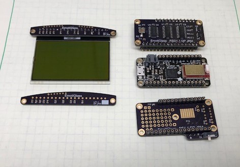
10/15/2018 at 03:58 • 0 comments![]()
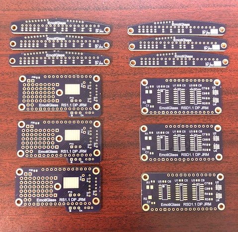
We received our PCBs from Osh Park and assembled 2 complete sets (one set, complete with the exception of one display, is shown above). Details about the build follow.---------- more ----------The first step after receiving the boards was to snap off the remaining route tabs and sand off the mouse bite protrusions. In some cases, this is necessary as the boards have only a little clearance around them in the frame. Where not critical, this goes a long way aesthetically. A few minutes with some 220 grit sandpaper is all it takes (note: observe proper precautions for working with fiberglass).
![]()
Next, I mounted the SMDs. All of the boards were designed to be easy to assemble with just an iron, but I reflowed the front and right side dev boards to save a little time. For those, I dispensed solder paste onto the pads with a syringe, then placed the components. A few minutes in the fancy toaster oven and they were ready for the next step. Because the right side boards only had one surface mount component each, I didn't bother with reflow and just popped those on with an iron.
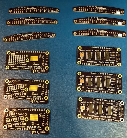
After reflow, I inspected all of the joints under the microscope and fixed any shorts or otherwise deficient joints. Next, the boards were cleaned.The
![]()
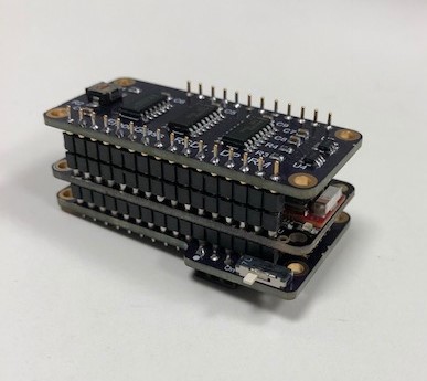
Lastly, all of the through hole components and the headers were installed. The final set is shown above; the PCB stack fully assembled is shown below.![]()
The next step is to test all of the boards and then assemble them onto a frame to make a complete prototype. -
Mechanical Design Complete
10/15/2018 at 03:32 • 0 comments![]()
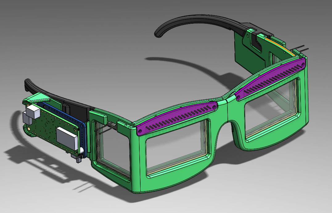
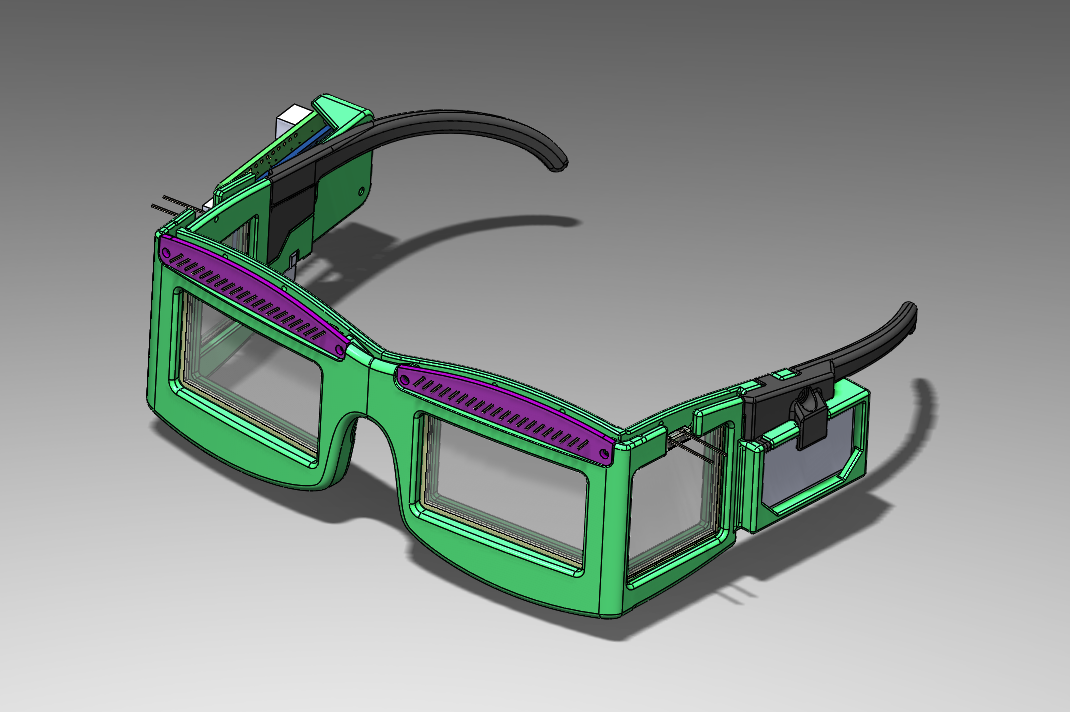
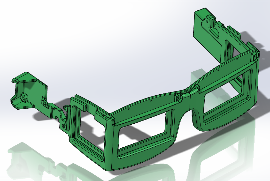
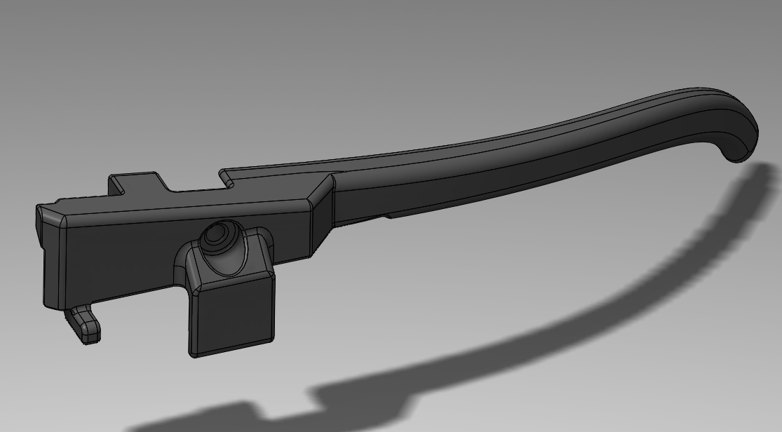
The CAD model for the EmotiGlass frame has been completed, and the printers are now busy making our prototype a reality. Provisions for mounting the PCB stack and LiPo battery were added to the previously printed frame design. The mounting arrangements for the side pieces were also changed to integrate with the mounting for the additional components. The side pieces were also updated with the feedback from the human fit test.
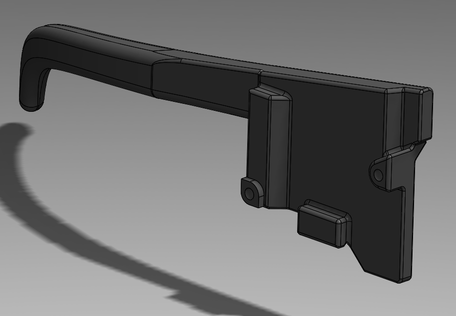
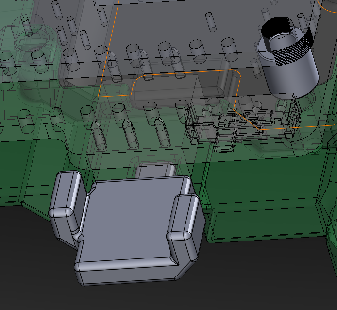
In addition to the 3 major frame pieces, 2 additional small parts were modeled. One is the key which will be glued onto the pulse sensor connector so that it cannot be inserted backwards, the other is just a spacer for the board stack (the mating distance is an odd size (~4.2mm) for which spacers are not available off the shelf.)
STL files for all parts have been uploaded. Screenshots below show the other side of the full assembly and individual views of the components.
---------- more ----------![]()
![]()
![]()
![]()
![]()
-
Mechanical Design Update – Human Fit Test
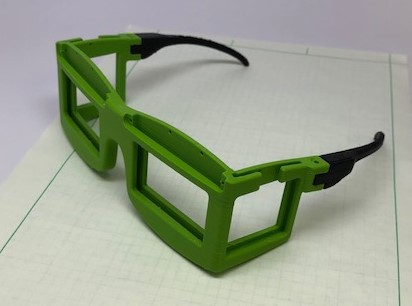
10/11/2018 at 23:42 • 0 comments![]()
While the previous test prints had determined the fit of the major components into the EmotiGlass frame, the equally important fit of the frame onto a human head had not yet been fully tested. Also, the exact position of the battery and electronics stack had yet to be finalized. To allow progress, an initial design for the side pieces (temporarily omitting mounting provisions for the electronics) was modeled and printed. This allowed the frame to be positioned on a human head and various aspects evaluated. The following conclusions were generated which will be implemented in the next few days:
-The placement of the displays is slightly below center of the eyes. This is desirable, as it allows for adjustability. I plan to design and 3d print spacers to clip onto the bridge (possibly, in more than one size) to allow the positioning to be easily adjusted to different noses.
-The shape of the arms works well but could be improved by extending them further back and down slightly.
-There appears to be space to mount the electronics stack and batteries directly between the side shutters and the ear, and elevating them as previously planned won’t be necessary. (these will be stood off slightly so that even if they do overlap with the ears they won’t interfere).
I'm hoping to complete the CAD model and 3d print the final frame in the next few days, which will be an exciting milestone. -
Wearable Prototype Schematics and PCB Layouts Finalized
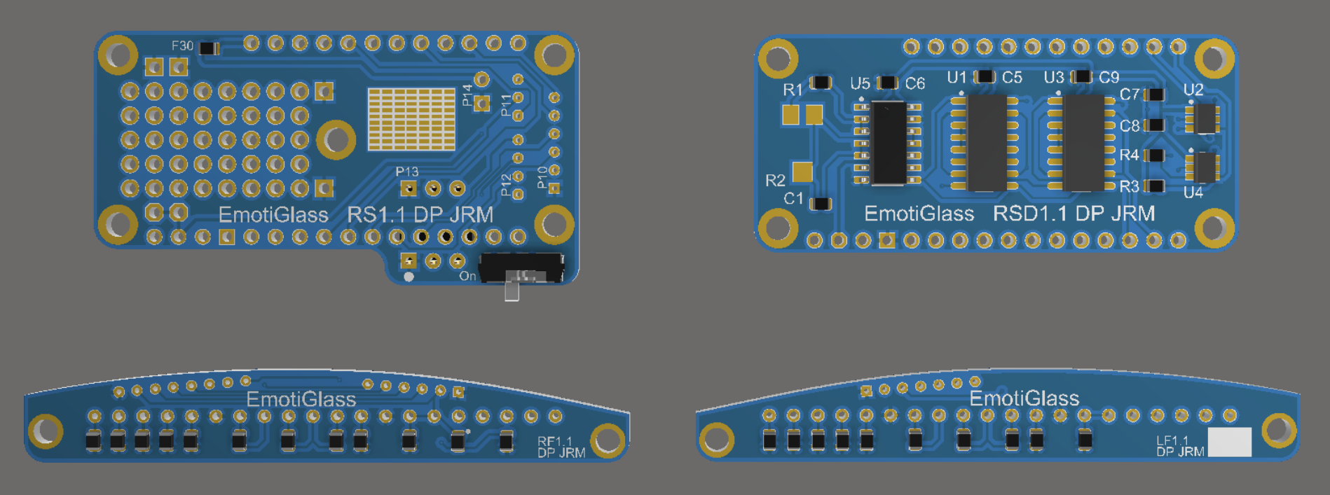
10/11/2018 at 23:04 • 0 comments![]()
We’ve been making a lot of exciting progress towards the completion of the wearable prototype design. The wearable prototype schematics have been finalized at revision 1.1, which has been uploaded. The only major change in this revision is the removal of the potentiometers used for control, as the GUI has advanced to the point where they have been deprecated.
The wearable prototype breaks the circuitry into 4 small PCBs:
The right side pcb mounts to the frame and provides a termination point for all of the wiring going to the other boards and to the components which don’t mount directly to a PCB (side shutters and battery). The feather plugs into this board, which contains a fuse on the battery input and a soft power switch. It also contains a socket for the pulse sensor to plug into, which was intentionally selected and oriented so that it will easily disconnect if the wire is accidentally pulled. The shape of this board was driven by the feather, so there was extra space which was filled with prototyping area to facilitate rework or feature addition in the future.
The right front and left front PCBs contain the capacitors needed for operating the LCD displays. The right side also contains the light sensor for the auto darkening function.
The right side dev PCB contains the hardware LCD drivers. These will be replaced by firmware, eventually, which is why they are on a separate PCB. This PCB will stack on top of the feather.
Layout of these 4 PCBs has been completed, and they have been submitted to OSH Park for manufacturing. The gerber zips and a draft of a pdf with layout prints and assembly annotations have been uploaded (this will be updated after we assemble our initial batch). We’ve selected the largest surface mount packages available for ICs (mostly SOIC’s) and are using 0603 passives (with plenty of space between them) so that the boards will be reasonable to assemble with only a basic soldering iron.
The boards are designed to be directly wired to each other. A number of interconnect options were considered, but this ended up being the simplest and lowest profile option. While it will be time consuming to assemble, this is acceptable for a few prototypes. 30 awg wire wrap wire will be used for most signals. Wire with Kynar or Teflon insulation is highly recommended. Power and ground will use something slightly larger, probably 26 awg. A draft of the wiring diagram has been uploaded (this will be updated with any changes we make during initial assembly).
Lastly, a draft BOM which contains only the electronic components has been uploaded. This will be updated to include the mechanical components shortly.
-
New EmotiGlass GUI Prototype Running
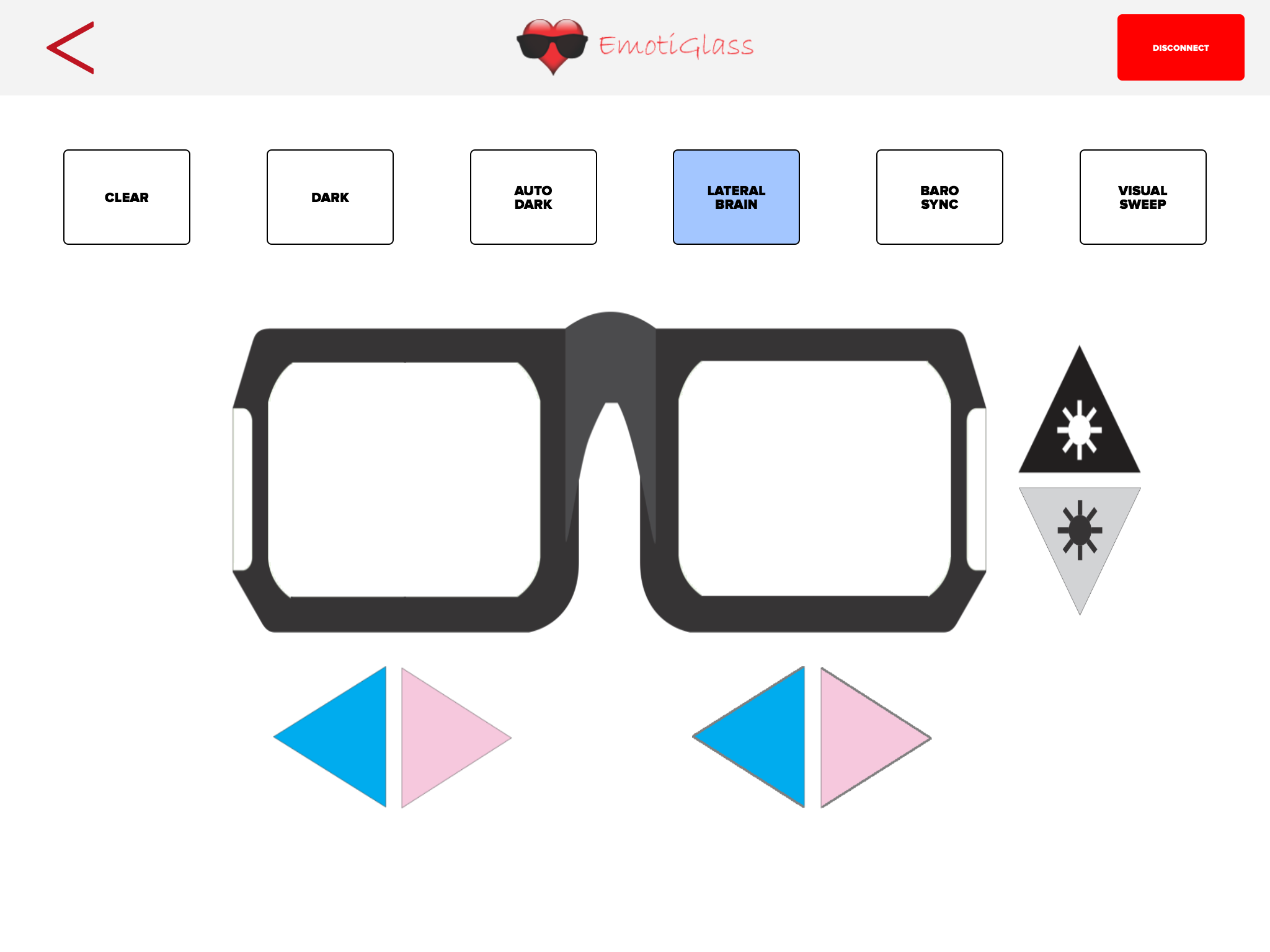
10/07/2018 at 13:54 • 0 commentsThanks to the great Greg Leonberg who knows how to code HTML/JavaScript, we now have a nice, intuitive GUI to control EmotiGlass via BLE. We are still cleaning the firmware and GUI. We'll post source as soon as we are done.
For now, this is a screen shot of the GUI running on the mini iPad under EvoThings:
![]()
EmotiGlass
A new device to change the user's emotional perception of reality.
 A second copy of the wearable prototype has been completed. The build for this prototype was documented and photographed so that we could provide easy to follow build instructions. The build instructions document has been uploaded.
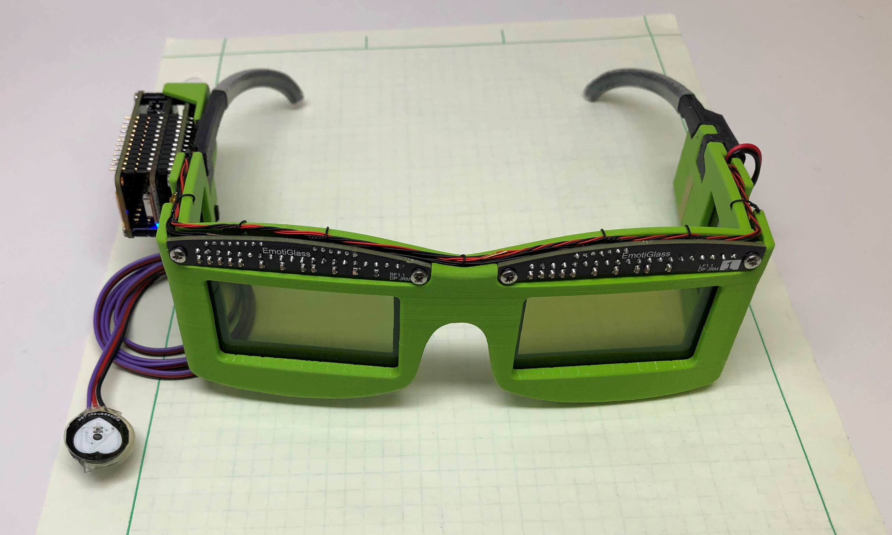 We are very excited to post that the first wearable prototype of EmotiGlass is now complete. We have confirmed that the device powers on and accepts commands via bluetooth, and that all operating modes are functional.