David Prutchi
-
Prototype GUI running under Evothings Studio
09/28/2018 at 01:43 • 0 commentsJust got a prototype BLE GUI for EmotiGlass running under Evothings Studio 2.2.1. The iOS Evothings player is CGTek 1.0.6.
![]()
-
Wearable Prototype Progress: First Print
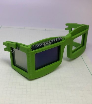
09/17/2018 at 23:09 • 0 commentsThe CAD model for the wearable prototype has progressed, and a first rev of the main frame piece has been printed. The frame is being designed with the front and 2 sides as separate parts. This allows the front piece which holds the glass LCD displays and shutters to be printed from a stiff plastic (PLA for now, but I may eventually switch to a CPE family material so I don't have to worry about leaving the print in a hot car), allowing it to provide the most protection possible to the glass. At the same time, the sides can be printed from a more flexible material from the Nylon family, which will allow the Emotiglass prototype to fit on heads of different sizes (hopefully) without being uncomfortable.
![]()
As soon as I completed the model for the front frame piece, I wanted to print it because I was expecting to need to make some adjustments to the fit. This part takes about 11 hours using a .4mm nozzle in an Ultimaker 2+. Sticking to this smaller sized nozzle makes it possible to remove the support material without too much hassle. After clearing the support and a few minutes of filing, I was able to test the fit of the components:
![]()
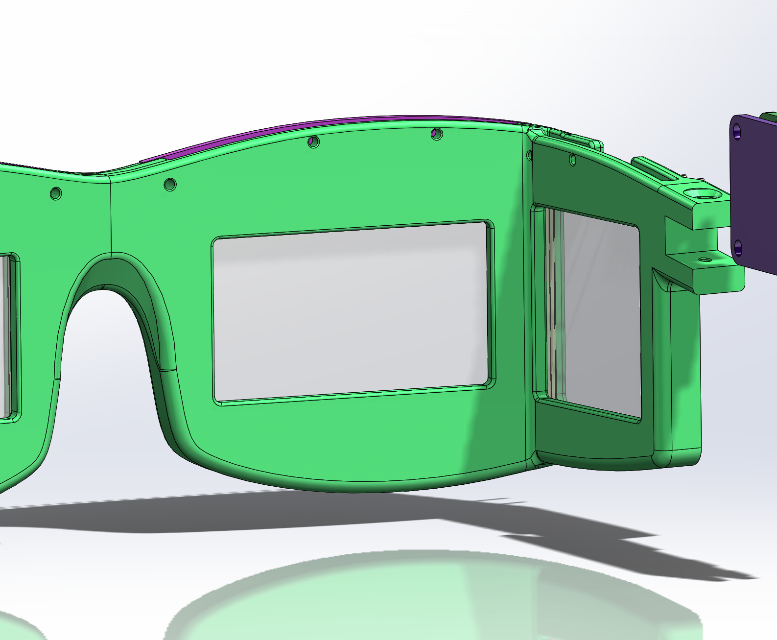
The fit on the display and shutter came out very well for a first test, needing adjustments of less than a millimeter. The fit on a face, on the other hand, wasn't as good. We tried holding the part on a few different faces, and concluded that the bridge needed to move down significantly. Additionally, I've flattened out the area above the bridge in the hopes that that may improve comport:
![]()
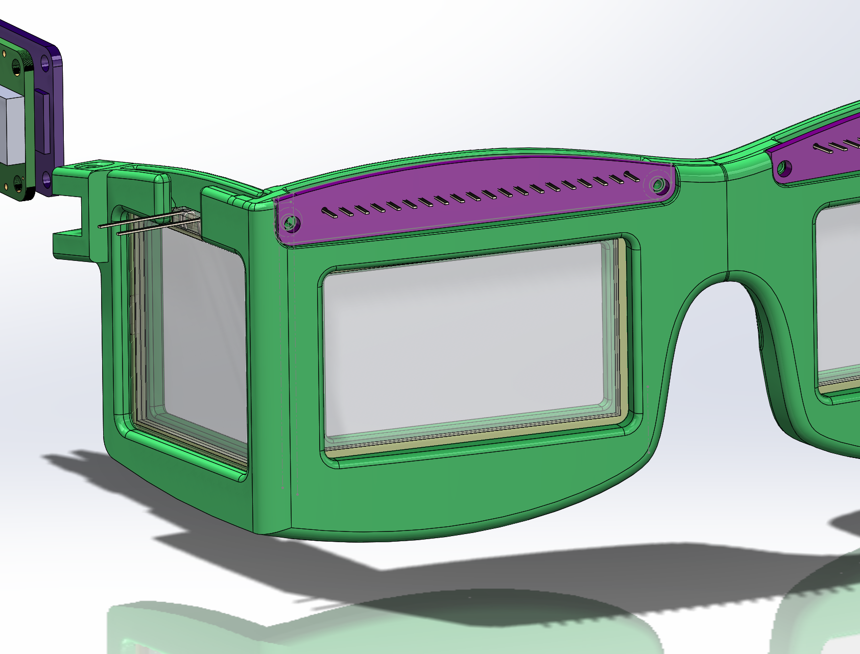
As the second rev prints, focus shifts back to the PCB layouts. The initial outlines are transferred from this model into Altium for PCB layout to see how everything fits. There is room to extend the PCBs downward somewhat, so they'll be adjusted as needed. The PCB shapes are shown in purple in the following image. 2 screws (not shown in the model) will secure the boards. The holes are sized to support either imperial or metric hardware - a #2x1/4" or M2x6. The holes are sized for standard (cheap) machine or sheet metal screws.![]()
With the front cad close to done, focus will shift back to the electronics. I'll swing back to the cad model and finish the sides after the boards are ordered. -
Wearable Prototype Schematics and Simplifying the Hardware Design
08/27/2018 at 06:18 • 0 commentsThe schematics for the wearable prototype have been uploaded, with each sheet corresponding to a small PCB with a portion of the EmotiGlass circuitry. Sheet 1 shows the right side PCB, which makes the connections between the Feather and the rest of the system. Sheets 2 and 3 are the front PCBs, which mount to the front LCD displays. They contain the support components necessary for the LCD Displays, connections for the side LCD shutters, and connections to other parts of the system. Sheet 4 shows the development PCB, which contains the control pots and hardware PWM circuitry. This board will be mounted on top of the feather, which is mounted on top of the right side PCB.
Currently, the side LCD shutters are driven by a dedicated hardware PWM circuit. DC will degrade the shutters over time, so they must be driven by a circuit with no net DC. A standard PWM peripheral is not able to do this, but it appears that the TCC modules (Timer/Counter for Control) in the Atmel SAMD21 processors (the ARM Cortex M0+ based microcontroller used by this feather) will be able to generate balanced PWM drive signals with no external circuitry. The firmware module for this will be written while we are waiting for PCBs to be manufactured.
The control pots are present primarily for convenience during prototyping. As development advances, their function will be replaced eventually by software. For this reason, the pots and the hardware PWM circuitry have been placed on a separate board. This board can be installed for initial work with the wearable prototype, and then removed once the firmware and software have advanced sufficiently.
The completed wearable prototype schematics allow work on the PCB layouts to proceed together with the mechanical design of the frame, which is currently partially complete.
-
Short videos of EmotiGlass breadboard prototype in operation
08/23/2018 at 21:00 • 0 commentsFollowing are three short videos showing the basic functionality of the EmotiGlass breadboard prototype.
We added some backlighting (using a strip of EL material) to show the way in which the device causes selective occlusion. The user's eyes would be on the side of the EL material looking at the scene through the liquid-crystal panels.
First is the breadboard operating in Baroreceptor-Synchronized Occlusion mode:
The pulse sensor is on Jason's finger. We can control the occlusion pattern as well as the timing of the occlusion versus the plethysmographic signal.
Next is the breadboard being controlled to produce a window for lateralized brain stimulation (we are showing functionality of controls, rather than actual occlusion that would be used for lateralized stimulation):
Lastly, the sunglasses mode (David casts a shadow on the light sensor):
-
Wearable Prototype Plan and Mechanical Design Start
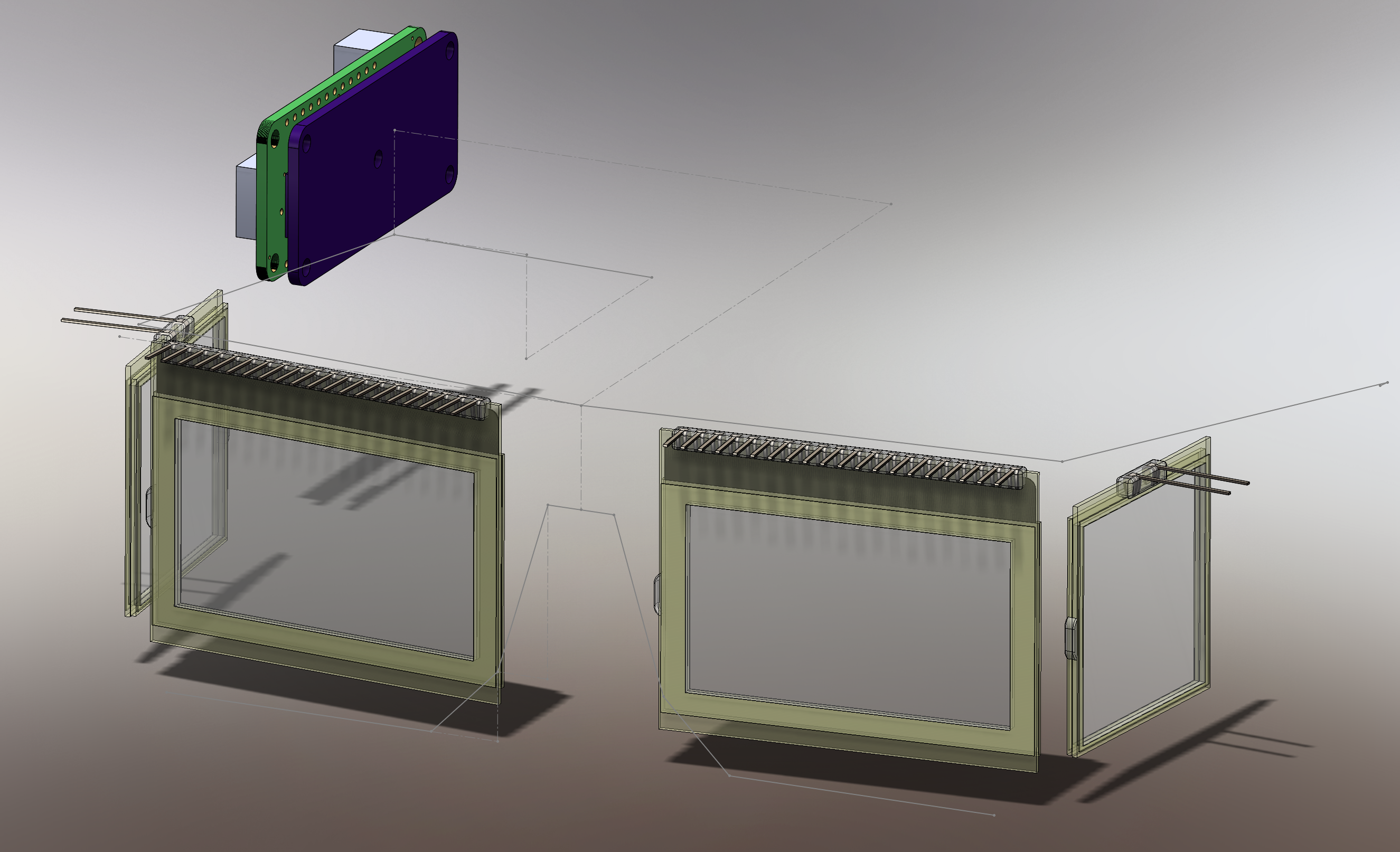
08/22/2018 at 22:58 • 0 commentsWith the breadboard operational, the next step is to develop a wearable prototype. Our plan is to 3D-print a frame with a shape similar to traditional glasses which will hold all of the components while being (reasonably) comfortable to wear. The LCD displays and shutters will fit into grooves in the frame which will capture them on 3 sides. The front LCD displays will each be mounted to a small PCB which will then attach to the frame with 2 screws, securing those displays in place. The side LCD shutters will be retained by a small bracket. A carrier PCB for the Feather PCB will be mounted above the right ear, and the battery will be mounted above the left ear.
Before modeling the frame, it was necessary to develop CAD models of the major components. The LCD display and LCD shutter models were built using the datasheets (where possible) and plenty of measurements of the actual components. The board outline for the Feather was exported from Eagle, and blocks representing keepout zones for the larger board components were added from measurements.
A 3D guide sketch for the glasses was developed based on measurements of my face and of a pair of cheap sunglasses which were a giveaway at last year’s Maker Faire. This is only a starting point, as it will probably take a few iterations to make the shape and size feel comfortable. The major components were arranged on the guide sketch so that modeling of the frame could begin.
![]()
-
Breadboard Schematic Uploaded
08/22/2018 at 22:01 • 0 commentsThe complete schematic for the EmotiGlass Breadboard has been captured and added to the project files.
-
EmotiGlass Breadboard Prototype Code v9.0
08/22/2018 at 20:01 • 0 commentsThe code is running (but may still contain some bugs and leftover debugging/engineering lines), and control is via BLEusing theBluefruit Control Pad running on the iOS Bluefruit app.
Here is the prototype Arduino code to run the EmotiGlass breadboard:
/* ************************************************************ * EMOTIGLASS BREADBOARD PROTOTYPE LIQUID-CRYSTAL GOGGLES * * ------------------------------------------------------ * ************************************************************ (c) 2018, David Prutchi and Jason Meyers Licensed under the MIT License Permission is hereby granted, free of charge, to any person obtaining a copy of this software and associated documentation files (the "Software"), to deal in the Software without restriction, including without limitation the rights to use, copy, modify, merge, publish, distribute, sublicense, and/or sell copies of the Software, and to permit persons to whom the Software is furnished to do so, subject to the following conditions: The above copyright notice and this permission notice shall be included in all copies or substantial portions of the Software. THE SOFTWARE IS PROVIDED "AS IS", WITHOUT WARRANTY OF ANY KIND, EXPRESS OR IMPLIED, INCLUDING BUT NOT LIMITED TO THE WARRANTIES OF MERCHANTABILITY, FITNESS FOR A PARTICULAR PURPOSE AND NONINFRINGEMENT. IN NO EVENT SHALL THE AUTHORS OR COPYRIGHT HOLDERS BE LIABLE FOR ANY CLAIM, DAMAGES OR OTHER LIABILITY, WHETHER IN AN ACTION OF CONTRACT, TORT OR OTHERWISE, ARISING FROM, OUT OF OR IN CONNECTION WITH THE SOFTWARE OR THE USE OR OTHER DEALINGS IN THE SOFTWARE. ABOUT THIS PROGRAM: ------------------- Runs on Adafruit Feather M0 Bluefruit Uses two DOGM128E-6 LCD displays made by "Electronic Assembly" and two small liquid-crystal shutters driven by two MCP4725 digital-to-analog converters through DC-AC converter. Control is via Bluefruit Control Pad running on iOS Bluefruit app This version implements: Mode 1 = Lateralized occlusion Mode 2 = Cardiac-synchronized lateralized occlusion Mode 3 = Automatic light-controlled sunglasses v.9 Adds control of two MCP4725A1 DACs to control contast of side shutters */ #include <Arduino.h> #include <string.h> #include <SPI.h> // DOG128E-6 LCD display #include <dog_7565R.h> //Library for DOG128E-6 displays (dog_7565R is the LCD controller) // Adafruit BLE #include "Adafruit_BLE.h" #include "Adafruit_BluefruitLE_SPI.h" #include "Adafruit_BluefruitLE_UART.h" #include "BluefruitConfig.h" // Asafruit MCP4725 digital-to-analog converters #include <Wire.h> #include <Adafruit_MCP4725.h> /* ******************************************************************* * Pin connections between LCDs and M0 Feather Board: * * ------------------------------------------------------------ * * LCD Arduino * * --- --------------------------------------------- * * 40 (CS) Specific to LCD: Right Front 10, Left Front 12 * * 39 (Reset) 5 * * 38 (A0) 9 * * 37 (SCL) SPI SCK * * 36 (SI) MOSI * ******************************************************************* Available functions in dog_7565R (LCD controller) Library: ---------------------------------------------------------- void initialize (byte p_cs, byte p_si, byte p_clk, byte p_a0, byte p_res, byte type); void clear (void); void contrast (byte contr); void view (byte direction); void string (byte column, byte page, const byte *font_adress, const char *str); void rectangle (byte start_column, byte start_page, byte end_column, byte end_page, byte pattern); void picture (byte column, byte page, const byte *pic_adress); Use of rectangle Description:Draws a filled rectangle on the screen. The filling is given through the pattern byte Name:void rectangle (byte start_column, byte start_page, byte end_column, byte end_page, byte pattern); Vars:start column (0..127 / 0..131), start page (0..7 / 0..3), end column (0..127 / 0..131), end page (0..7 / 0..3), pattern-byte to fill area */ //Define operating mode //--------------------- /* Mode 1 = Lateralized occlusion Mode 2 = Cardiac-synchronized lateralized occlusion Mode 3 = Automatic light-controlled sunglasses */ int mode=1; /*========================================================================= APPLICATION SETTINGS FACTORYRESET_ENABLE Perform a factory reset when running this sketch Enabling this will put your Bluefruit LE module in a 'known good' state and clear any config data set in previous sketches or projects, so running this at least once is a good idea. When deploying your project, however, you will want to disable factory reset by setting this value to 0. If you are making changes to your Bluefruit LE device via AT commands, and those changes aren't persisting across resets, this is the reason why. Factory reset will erase the non-volatile memory where config data is stored, setting it back to factory default values. Some sketches that require you to bond to a central device (HID mouse, keyboard, etc.) won't work at all with this feature enabled since the factory reset will clear all of the bonding data stored on the chip, meaning the central device won't be able to reconnect. MINIMUM_FIRMWARE_VERSION Minimum firmware version to have some new features MODE_LED_BEHAVIOUR LED activity, valid options are "DISABLE" or "MODE" or "BLEUART" or "HWUART" or "SPI" or "MANUAL" -----------------------------------------------------------------------*/ #define FACTORYRESET_ENABLE 1 #define MINIMUM_FIRMWARE_VERSION "0.6.6" #define MODE_LED_BEHAVIOUR "MODE" /*=========================================================================*/ // Create the Bluefruit object /* ...hardware SPI, using SCK/MOSI/MISO hardware SPI pins and then user selected CS/IRQ/RST */ Adafruit_BluefruitLE_SPI ble(BLUEFRUIT_SPI_CS, BLUEFRUIT_SPI_IRQ, BLUEFRUIT_SPI_RST); // DAC Control Adafruit_MCP4725 dac; // A small helper void error(const __FlashStringHelper*err) { Serial.println(err); while (1); } // function prototypes over in packetparser.cpp uint8_t readPacket(Adafruit_BLE *ble, uint16_t timeout); float parsefloat(uint8_t *buffer); void printHex(const uint8_t * data, const uint32_t numBytes); // the packet buffer extern uint8_t packetbuffer[]; int button=0; // define LCD and liquid crystal shutter control pins int rightfrontCS = 10; // right front LCD chip select int rightsideCS = 11; // right side (peripheral vision) shutter select int leftfrontCS = 12; // left front LCD chip select int leftsideCS = 13; // left side (peripheral vision) shutter select // define plethysmography sensor power pin and Arduino analog input pin for plethysmography sensor int plethPin = A0; // Analog output pin for plethysmography sensor int plethPower = 0; // Pin use to power plethysmography sensor // define light sensor power pin and Arduino analog input pin for light sensor int lightPin = A5; // Pin for light sensor int lightValue = 0; // Variable for light sensor // define analog input pins for UI potentiometers int pot1Pin = A1; // Pin for potentiometer 1 int pot1Value = 0; // Variable for pot1 measurement int pot2Pin = A2; // Pin for potentiometer 2 int pot2Value = 0; // Variable for pot2 measurement int pot3Pin = A3; // Pin for potentiometer 2 int pot3Value = 0; // Variable for pot2 measurement int pot4Pin = A4; // Pin for potentiometer 2 int pot4Value = 0; // Variable for pot2 measurement // define variables int change = true; // Variable for GUI change int rightfrontContrast = 0; // Variable for contrast of right eye front contrast (0...63) int oldrightfrontContrast =0; int rightsideContrast = 0; // Variable for contrast of right eye side contrast (0...63) int oldrightsideContrast =0; int leftfrontContrast = 0; // Variable for contrast of left eye front contrast (0...63) int oldleftfrontContrast =0; int leftsideContrast = 0; // Variable for contrast of right eye side contrast (0...63) int oldleftsideContrast =0; int rightSpan = 0; // Span of occlusion for right eye int oldrightSpan = 0; int rightfrontStart=0; //Occlusion start for right front LCD int rightfrontEnd=0; //Occlusion end for the right front LCD int rightsideEnable=0; //Occlusion for right side shutter int leftSpan = 0; // Span of occlusion for left eye int oldleftSpan = 0; int leftfrontStart=0; //Occlusion start for left front LCD int leftfrontEnd=0; //Occlusion end for the left front LCD int leftsideEnable=0; //Occlusion for left side shutter int baroreceptor=0; //Duration of occlusion after detection of baroreceptor activation int plethValue = 512; // holds the incoming raw plethysmography sensor data (0..1023) int plethThreshold = 550; // Plethysmography signal threshold for beat sensing /* These variables are the output of the windowLCD function. In a nice language I could have the function * return multiple values, but not in C++ without using structures or pointers. Screw C++ !! I'm declaring these as global variables and will use them only in windowLCD */ int frontStart = 0; int frontEnd=0; int sideEnable=0; dog_7565R DOG; void windowLCD(int Span){ /* windowLCD - Function to calculates start and end of occlusion for LCDs ------------------------------------------------------------------- Input: Span (0..255) Returns: frontStart frontEnd sideEnable sideEnd */ if (Span < 128) // occlusion is fully within front LCD { frontStart=0; frontEnd=Span; sideEnable=0; } else { frontStart=Span-128; frontEnd=127; sideEnable=1; } // // End of function windowLCD() } void updateLCDs(int rightfrontStart, int rightfrontEnd, int rightfrontContrast, int rightsideEnable, int rightsideContrast, int leftfrontStart, int leftfrontEnd, int leftfrontContrast, int leftsideEnable, int leftsideContrast){ /* updateLCDs - Function to Update LCDs ------------------------------------ rightfrontStart = Occlusion start for right front LCD (0..127) rightfrontEnd = Occlusion end for the right front LCD (0..127) rightfrontContrast = Contrast for the right front LCD rightsideEnable = Occlusion enable for right side liquid-crystal light shutter rightsideEnd = Occlusion end for right side LCD rightsideContrast = Contrast for the right side LCD leftfrontStart = Occlusion start for left front LCD leftfrontEnd = Occlusion end for the left front LCD leftfrontContrast = Contrast for the left front LCD leftsideEnable = Occlusion enable for left side liquid-crystal light shutter leftsideContrast = Contrast for the left side LCD */ // Update Right Front LCD DOG.initialize(rightfrontCS,0,0,9,99,DOGM128); // Reset pin is identified as '99' so that it doesn't reset LCDs DOG.view(VIEW_BOTTOM); //default viewing direction DOG.contrast(rightfrontContrast); //contrast (0..63) DOG.rectangle(rightfrontStart,0,rightfrontEnd,7,0xFF); // Update Left Front LCD DOG.initialize(leftfrontCS,0,0,9,99,DOGM128); // Reset pin is identified as '99' so that it doesn't reset LCDs DOG.view(VIEW_TOP); //alternate viewing direction DOG.contrast(leftfrontContrast); //contrast (0..63) DOG.rectangle(leftfrontStart,0,leftfrontEnd,7,0xFF); // Update Right Side shutter digitalWrite(rightsideCS,rightsideEnable); // Enable right side shutter // Update Left Side shutter digitalWrite(leftsideCS,leftsideEnable); // Enable left side shutter // // End of function updateLCDs() } void clearLCDs() { /* clearLCDs - Function to Clear LCDs and side Liquid Crystal Light Shutters ------------------------------------------------------------------------- */ // Clear Right Front LCD DOG.initialize(rightfrontCS,0,0,9,99,DOGM128); // Reset pin is identified as '99' so that it doesn't reset LCDs DOG.clear(); DOG.contrast(rightfrontContrast); //contrast (0..63) // Clear Right Side Shutter digitalWrite(rightsideCS,LOW); // Disable right side shutter // Clear Left Front LCD DOG.initialize(leftfrontCS,0,0,9,99,DOGM128); // Reset pin is identified as '99' so that it doesn't reset LCDs DOG.clear(); DOG.contrast(leftfrontContrast); //contrast (0..63) // Update Right Side shutter digitalWrite(leftsideCS,LOW); // Disable right side shutter // // End of function clearLCDs() } void setup() { // The next two lines force the Feather to be connected to a computer and the serial // terminal activated. Comment them after debugging so that board can work independently // while (!Serial); // Wait for serial terminal in Arduino IDE to be opened // delay(500); Serial.begin(115200); Serial.println(F("Goggles are Controlled by Adafruit Bluefruit App Controller")); Serial.println(F("-----------------------------------------------------------")); /* Initialize the Bluefruit LE module */ Serial.print(F("Initializing the Bluefruit LE module: ")); if ( !ble.begin(VERBOSE_MODE) ) { error(F("Couldn't find Bluefruit, make sure it's in CoMmanD mode & check wiring?")); } Serial.println( F("OK!") ); if ( FACTORYRESET_ENABLE ) { /* Perform a factory reset to make sure everything is in a known state */ Serial.println(F("Performing a factory reset: ")); if ( ! ble.factoryReset() ){ error(F("Couldn't factory reset")); } } /* Disable command echo from Bluefruit */ ble.echo(false); Serial.println("Requesting Bluefruit info:"); /* Print Bluefruit information */ ble.info(); Serial.println(F("Please use Adafruit Bluefruit LE app to connect in Controller mode")); Serial.println(F("Then activate/use the game controller")); Serial.println(); ble.verbose(false); // debug info is a little annoying after this point! /* Wait for BLE connection */ while (! ble.isConnected()) { delay(500); } Serial.println(F("******************************")); // LED Activity command is only supported from 0.6.6 if ( ble.isVersionAtLeast(MINIMUM_FIRMWARE_VERSION) ) { // Change Mode LED Activity Serial.println(F("Change LED activity to " MODE_LED_BEHAVIOUR)); ble.sendCommandCheckOK("AT+HWModeLED=" MODE_LED_BEHAVIOUR); } // Set Bluefruit to DATA mode Serial.println( F("Switching to DATA mode!") ); ble.setMode(BLUEFRUIT_MODE_DATA); Serial.println(F("******************************")); // DOG.initialize using hardware SPI: CS , 0 , 0= use Hardware SPI, 9 = A0, 5 = RESET, DOGM128-6 (=128x64 dots) DOG.initialize(rightfrontCS,0,0,9,5,DOGM128); DOG.view(VIEW_BOTTOM); //default viewing direction DOG.initialize(leftfrontCS,0,0,9,5,DOGM128); DOG.view(VIEW_BOTTOM); //default viewing direction // Initialize power pin for plethysmography sensor pinMode(plethPower,OUTPUT); // Initialize DACs - Adafruit MCP4725A1 address is 0x62 (default) or 0x63 (ADDR pin tied to VCC) dac.begin(0x62); dac.begin(0x63); // Initialize liquid crystal shutter AC drivers pinMode(rightsideCS,OUTPUT); pinMode(leftsideCS,OUTPUT); // // End of setup() } //main loop void loop() { // Poll for new BLE data uint8_t len = readPacket(&ble, BLE_READPACKET_TIMEOUT); if (len != 0) { change=true; // if a button was pressed, then set GUI change flag } // Read which one of the GUI buttons was pressed if (packetbuffer[1] == 'B') { uint8_t buttnum = packetbuffer[2] - '0'; Serial.print ("Button "); Serial.print(buttnum); button=(int)buttnum; // Decode the meaning of the button and update settings // ---------------------------------------------------- if (button == 1) { mode=1; digitalWrite(plethPower,LOW); // Turn off power to plethysmography sensor } if (button == 2) { mode=2; digitalWrite(plethPower,HIGH); // Turn on power to plethysmography sensor } if (button == 3) { mode=3; digitalWrite(plethPower,LOW); // Turn off power to plethysmography sensor } if (button == 8) { rightSpan=rightSpan+4; } if (button == 7) { rightSpan=rightSpan-4; } if (rightSpan <0){ rightSpan=0; } // Don't let rightSpan go below 0 if (rightSpan>255){ rightSpan=255; } // Don't let rightSpan go above 255 if (button == 6) { leftSpan=leftSpan+4;} if (button == 5) { leftSpan=leftSpan-4;} if (leftSpan <0) { leftSpan=0; } // Don't let leftSpan go below 0 if (leftSpan>255){ leftSpan=255;} // Don't let rightSpan go above 255 // Calculate start and end of occlusion for right-eye LCD windowLCD(rightSpan); rightfrontStart=frontStart; rightfrontEnd=frontEnd; rightsideEnable=sideEnable; // Calculate start and end of occlusion for right-eye LCDs windowLCD(leftSpan); leftfrontStart=frontStart; leftfrontEnd=frontEnd; leftsideEnable=sideEnable; } // Read UI potentiometers // ---------------------- pot1Value=analogRead(pot1Pin); // 10 bit A/D so value is between 0 and 1024 rightfrontContrast = pot1Value/16; // Contrast (0...63) rightsideContrast = pot1Value/16; // Contrast (0...63) leftfrontContrast = pot1Value/16; // Contrast (0...63) leftsideContrast = pot1Value/16; // Contrast (0...63) //pot2Value=analogRead(pot2Pin); // 10 bit A/D so value is between 0 and 1024 // rightSpan=pot2Value/4; //Span is two displays wide, so "curtain" is 128 wide and full window is 256 wide (0...255) //pot3Value=analogRead(pot3Pin); // 10 bit A/D so value is between 0 and 1024 //leftSpan=pot3Value/4; //Span is two displays wide, so "curtain" is 128 wide and full window is 256 wide (0...255) pot4Value=analogRead(pot4Pin); // 10 bit A/D so value is between 0 and 1024 baroreceptor=pot4Value/4; //Duration of occlusion after detection of baroreceptor activation (0..255 ms) if (mode == 1) { // Mode 1 is simple occlusion based on User Interface settings // // If there were any GUI changes, then update displays // --------------------------------------------------- if (change==true) // Update LCDs if there were changes in UI { // Now update the LCDs updateLCDs(rightfrontStart, rightfrontEnd, rightfrontContrast, rightsideEnable, rightsideContrast, leftfrontStart, leftfrontEnd, leftfrontContrast, leftsideEnable, leftfrontContrast); change=false; // Reset GUI change flag } // End of Mode 1 } if (mode == 2) { // Mode 2 is occlusion that is synchronized to baroreceptor activation // Read plethysmography sensor plethValue=analogRead(plethPin); // 10 bit A/D so value is between 0 and 1023 //Serial.println(plethValue); // Send the Signal value to Serial Plotter if(plethValue > plethThreshold) { // If the signal is above plethThreshold, then occlude vision // Now update the LCDs to occlude updateLCDs(rightfrontStart, rightfrontEnd, rightfrontContrast, rightsideEnable, rightsideContrast, leftfrontStart, leftfrontEnd, leftfrontContrast, leftsideEnable, leftfrontContrast); delay(baroreceptor); // Maintain occlusion while baroreceptors are activated by diastolic pressure wave clearLCDs(); // Clear LCDs once the baroreceptors are no longer active delay(300-baroreceptor); // Start a refractory period which ends ~300 ms after trigger } // End of Mode 2 } if (mode == 3) { // Mode 3 is for automatic sunglasses // // If there were any GUI changes, then update displays // --------------------------------------------------- if (change==true) // Run once when entering mode 3 { // Now update the LCDs rightfrontStart=0; rightfrontEnd=127; rightfrontContrast=63; leftfrontStart=0; leftfrontEnd=127; leftfrontContrast=63; rightsideEnable=1; rightsideContrast=63; leftsideEnable=1; rightsideContrast=63; updateLCDs(rightfrontStart, rightfrontEnd, rightfrontContrast, rightsideEnable, rightsideContrast, leftfrontStart, leftfrontEnd, leftfrontContrast, leftsideEnable, leftsideContrast); change=false; // Reset GUI change flag } lightValue=analogRead(lightPin); // 10 bit A/D so value is between 0 and 1024 rightfrontContrast = lightValue/16; // Contrast (0...63) leftfrontContrast = lightValue/16; // Contrast (0...63) rightsideContrast = lightValue*4; // Contrast (0...63) leftsideContrast = lightValue*4; // Contrast (0...63) DOG.initialize(rightfrontCS,0,0,9,99,DOGM128); // Reset pin is identified as '99' so that it doesn't reset LCDs DOG.contrast(rightfrontContrast); //contrast (0..63) DOG.initialize(leftfrontCS,0,0,9,99,DOGM128); // Reset pin is identified as '99' so that it doesn't reset LCDs DOG.contrast(leftfrontContrast); //contrast (0..63) dac.begin(0x62); dac.setVoltage(leftsideContrast, false); dac.begin(0x63); dac.setVoltage(rightsideContrast, false); // End of Mode 3 } // // End of main loop() } -
EmotiGlass Prototype Breadboard Working!
08/22/2018 at 19:39 • 0 commentsWe are in the process of cleaning the schematics and software, so we'll upload them a bit later. For now, here is a picture of the breadboard:
![]()
-
Changed light sensor part and added components
08/22/2018 at 19:02 • 0 commentsThe light sensor part was changed to the ALS-PT19 Analog Light Sensor Breakout Board (Adafruit 2748).
Added parts to the parts list for the breadboard to include passives and components for the H-bridge and oscillator that drive the side liquid-crystal panels with AC.
-
Core components for EmotiGlass Breadboard Prototype
08/22/2018 at 03:16 • 0 commentsA practical implementation of the EmotiGlass concept requires a pixelized light shutter with the following characteristics:
- Spatial resolution of at least 2mm
- Variable opacity and high contrast
- Response speed in the tens of milliseconds or better
After researching possible solutions for fully pixelized electro-optical elements, we settled on modular LCDs for the front lenses. We chose the DOGM128E-6 made by Electronic Assembly GmbH (Zeppelinstraße 19, D-82205 Gilching, Germany) because it allows full control of the pattern of visual occlusion, as well as the opacity level of the occluded and non-occluded areas.
![]()
The DOGM128E-6 is sold by Mouser and Digikey (around $23 each). The DOGM128E-6 is a high-contrast, 128x64 pixel LCD supertwist display with 15μm dot gap. It incorporates a ST7565R controller with SPI interface. The display module requires just a single 3.0 to 3.3V power supply (270μA typical) and can be directly mounted on a PCB. The LCD is compact (55x46x2 mm) with a large viewing area of 51x31 mm.
For the side panels we chose the “Small Liquid Crystal Light Valve - Controllable Shutter Glass” distributed by Adafruit as Product number 3627 ($2.95 each). The viewing window is 31x33 mm, while the panel size is 36x36x2 mm, making it suitable to mount on the sides of goggles based on the DOGM128E-6. The device is a transmissive twisted nematic panel and requires an AC drive voltage in the 3.0V range.
To make a first breadboard prototype of EmotiGlass as open-source as possible, we chose the controller to be an Arduino IDE-compatible Adafruit Feather M0 Bluefruit LE (Adafruit Product ID: 2995, $29.95). Power will be derived from a 3.7V 150mAh lithium ion polymer battery (Adafruit Product ID: 1317, $5.95) that can be recharged directly from the Feather.
For the breadboard prototype chose a ready-made plethysmography sensor (Pulse Sensor Amped, Adafruit Product ID: 1093, $25.00). ALS-PT19 Analog Light Sensor Breakout Board (Adafruit Product ID: 2748) is used for the “automatic sunglasses mode”.
A simple oscillator and analog H-bridge will be used to drive the side panels at an amplitude set by two MCP4725A1 DACs are used to control the side-panel shutters (MCP4725 Breakout Board - 12-Bit DAC w/I2C Interface, Adafruit Product ID: 935, $4.95).
EmotiGlass
A new device to change the user's emotional perception of reality.