-
11Build an Boom for the Forehead EEG Electrode That Clips Onto Glasses
![]()
Hydrate in style! FYI, Fiji water is a must. The shape of their bottle is ideal for the structural integrity of the clip-on glasses EEG electrode boom.
![]()
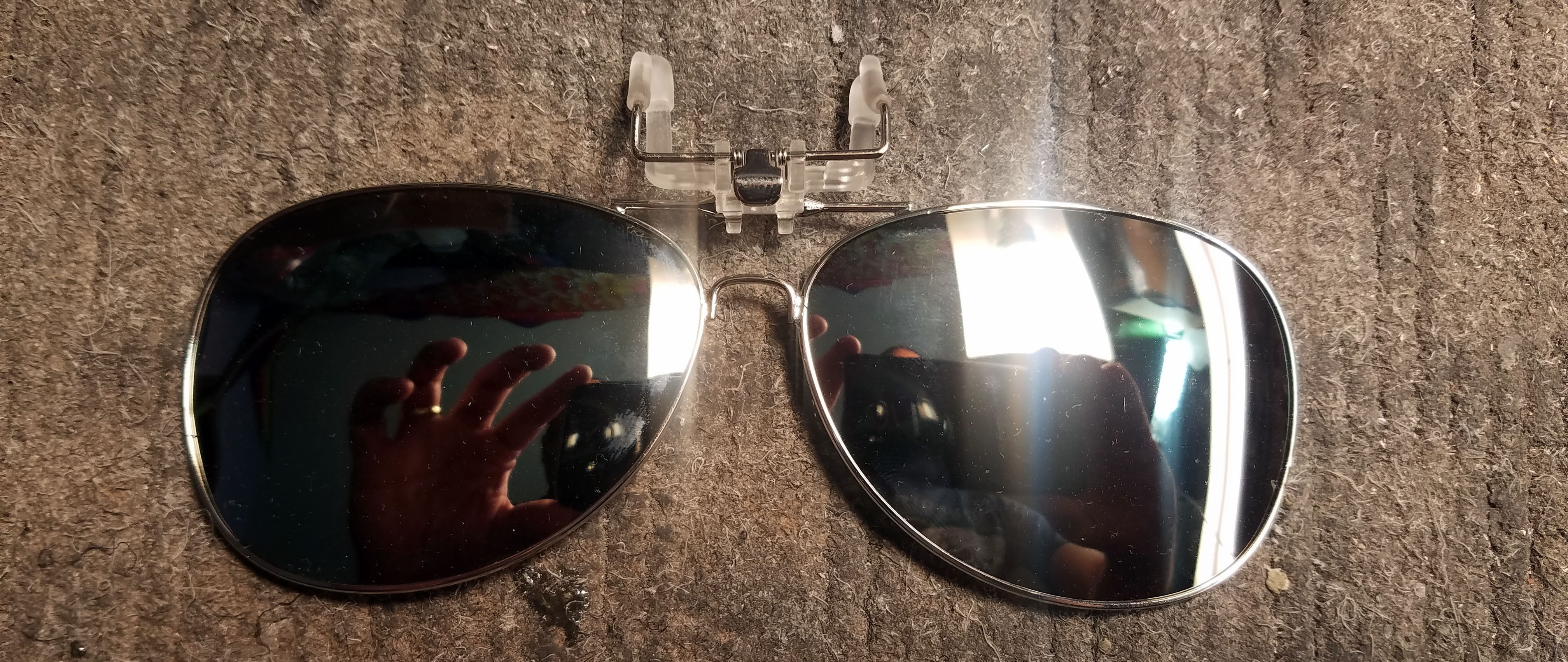
Cheap clip-on sunglasses. We only need the clip.
![]()
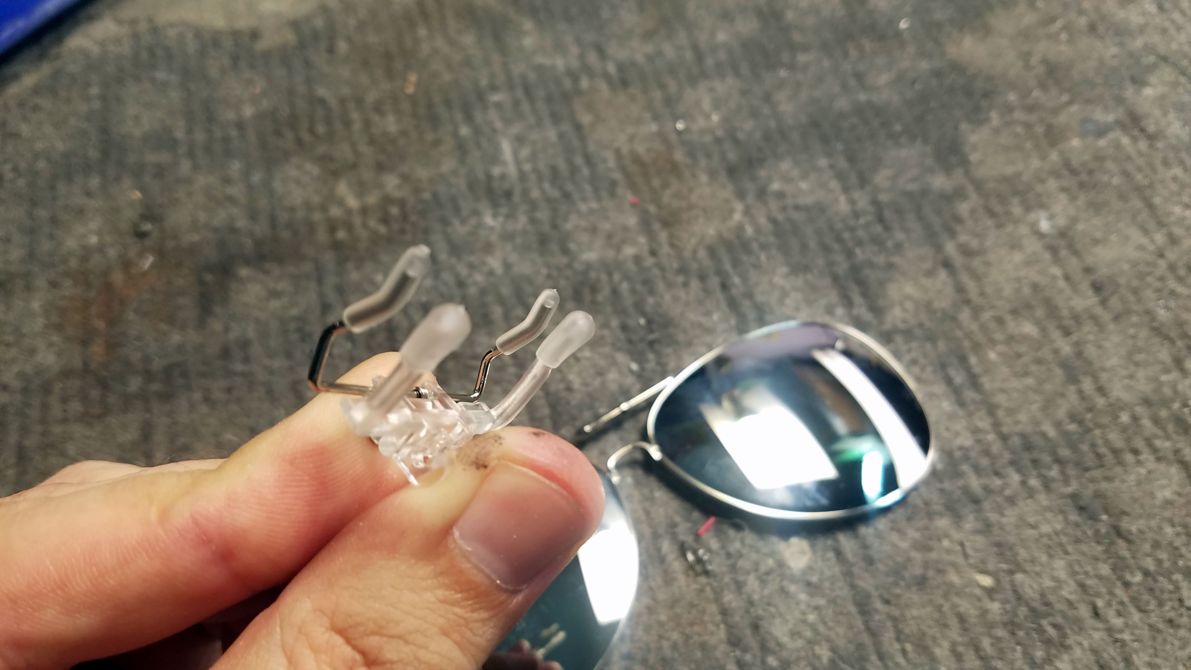
There pop right off. I carved off extraneous parts with a hobby knife.
![]()
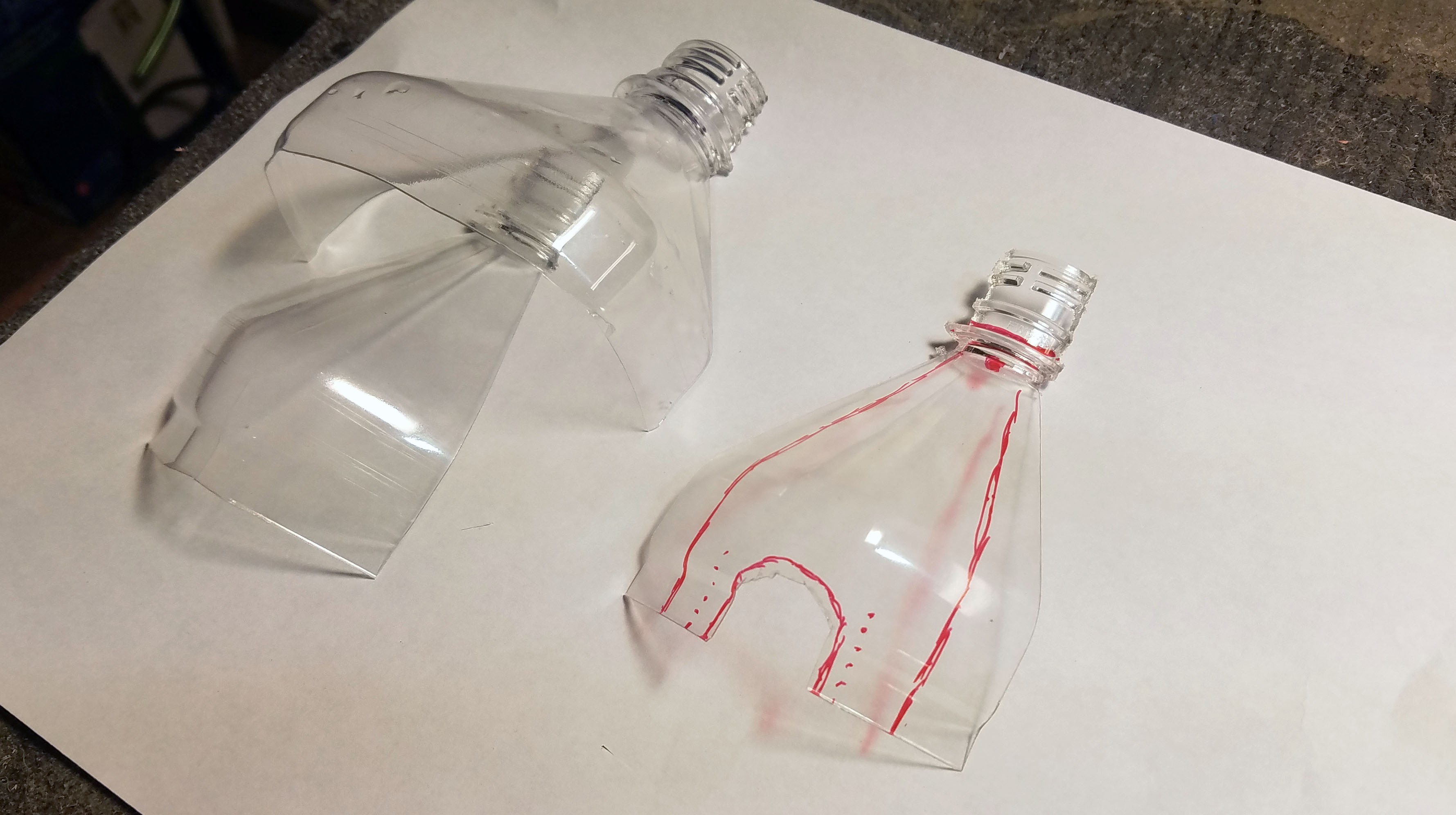
Nothing like flying H20 half way around the world for no reason. There isn't anything special about Fiji water, but their bottle does seem to be a cut above the rest.
![]()
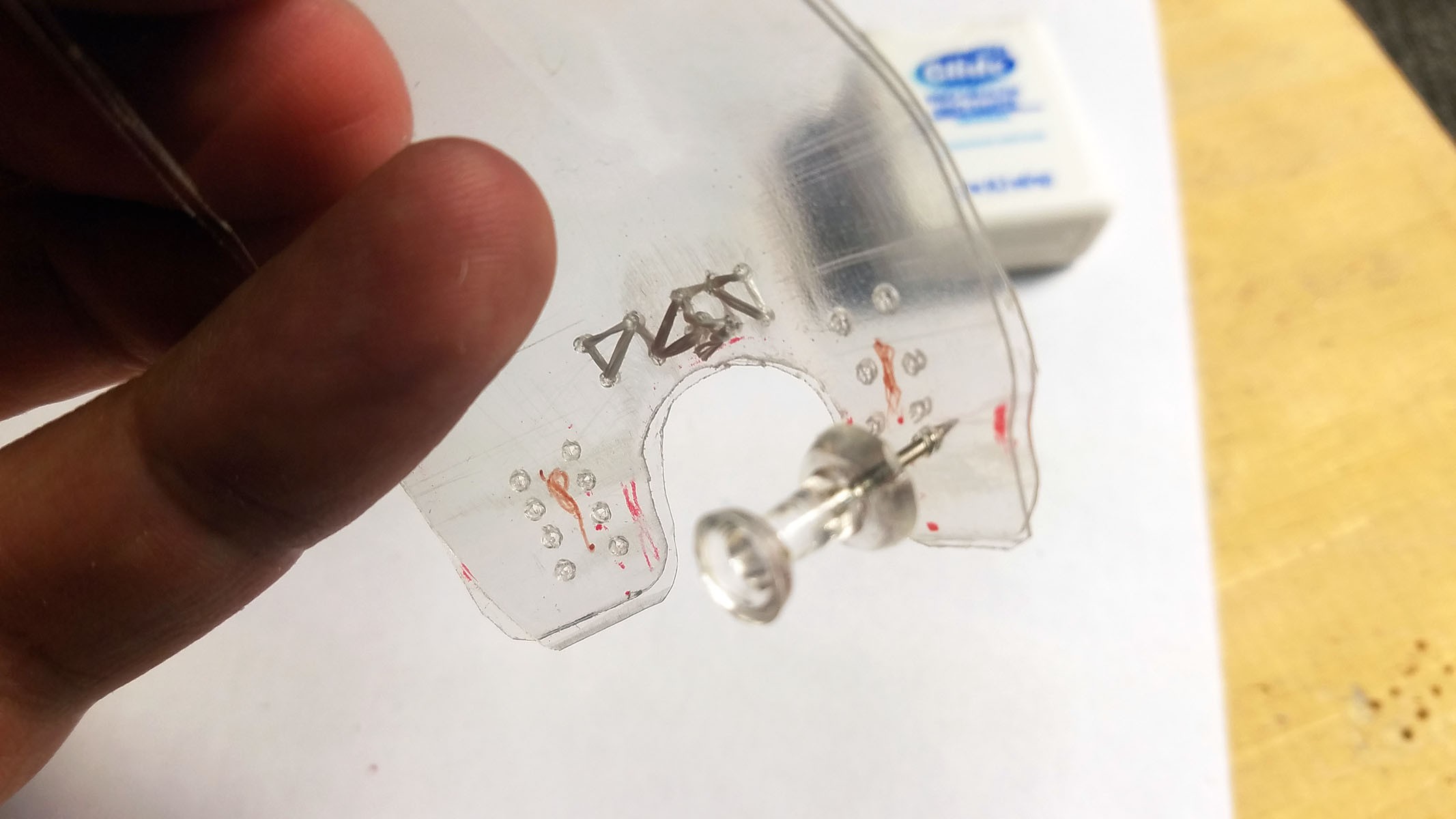
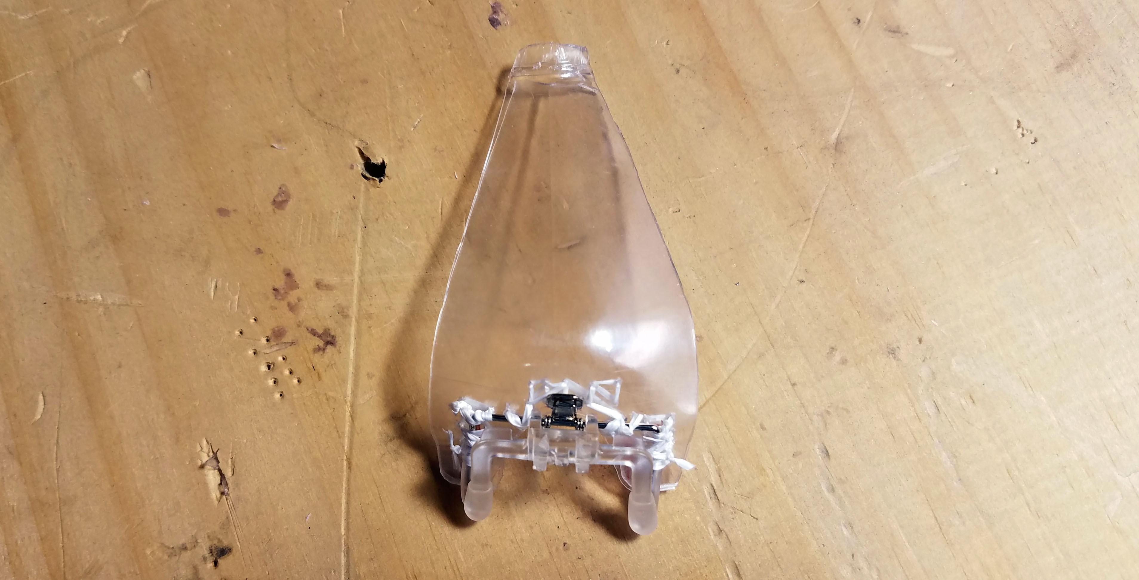
The corners of the pyramid shaped Fiji water bottle keep the plastic boom from flopping forward when the EEG electrode is pressed against your head. I did two layers of plastic just to keep my bases covered but one is probably all thats necessary.
![]()
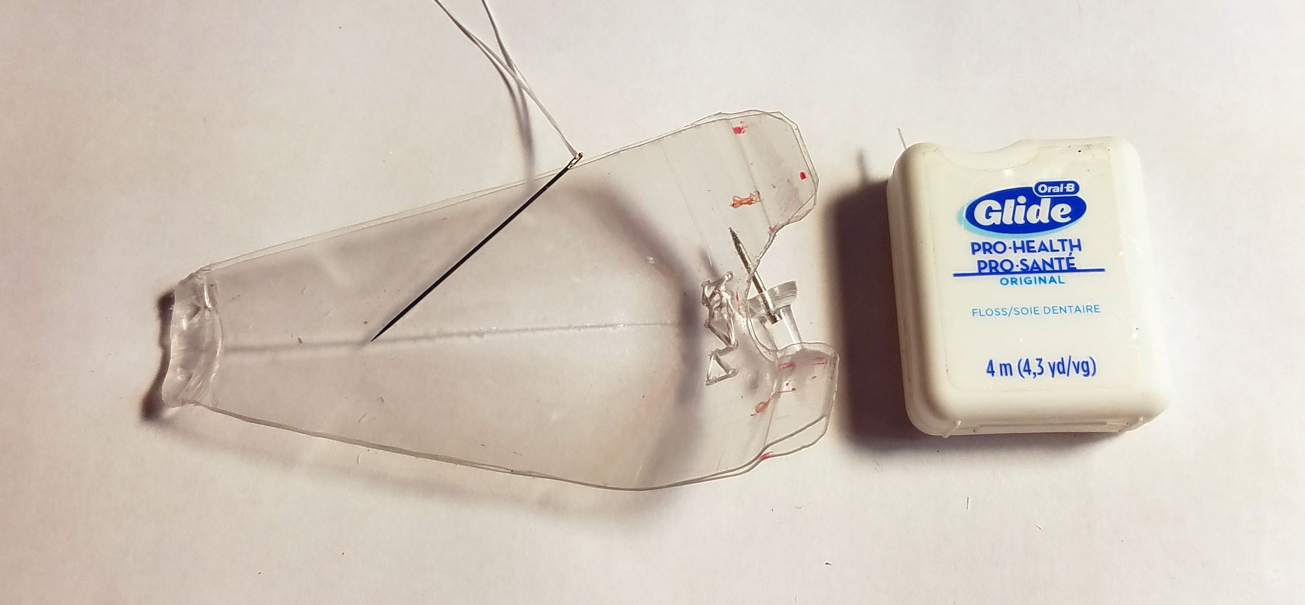
Sewing is a hacker's secret weapon. I got in the habit of sewing with dental floss back in my train hopping crust punk days.
![]()
![]()
-
12Build Frontal Lobe Sensing EEG Electrode
![]()
![]()
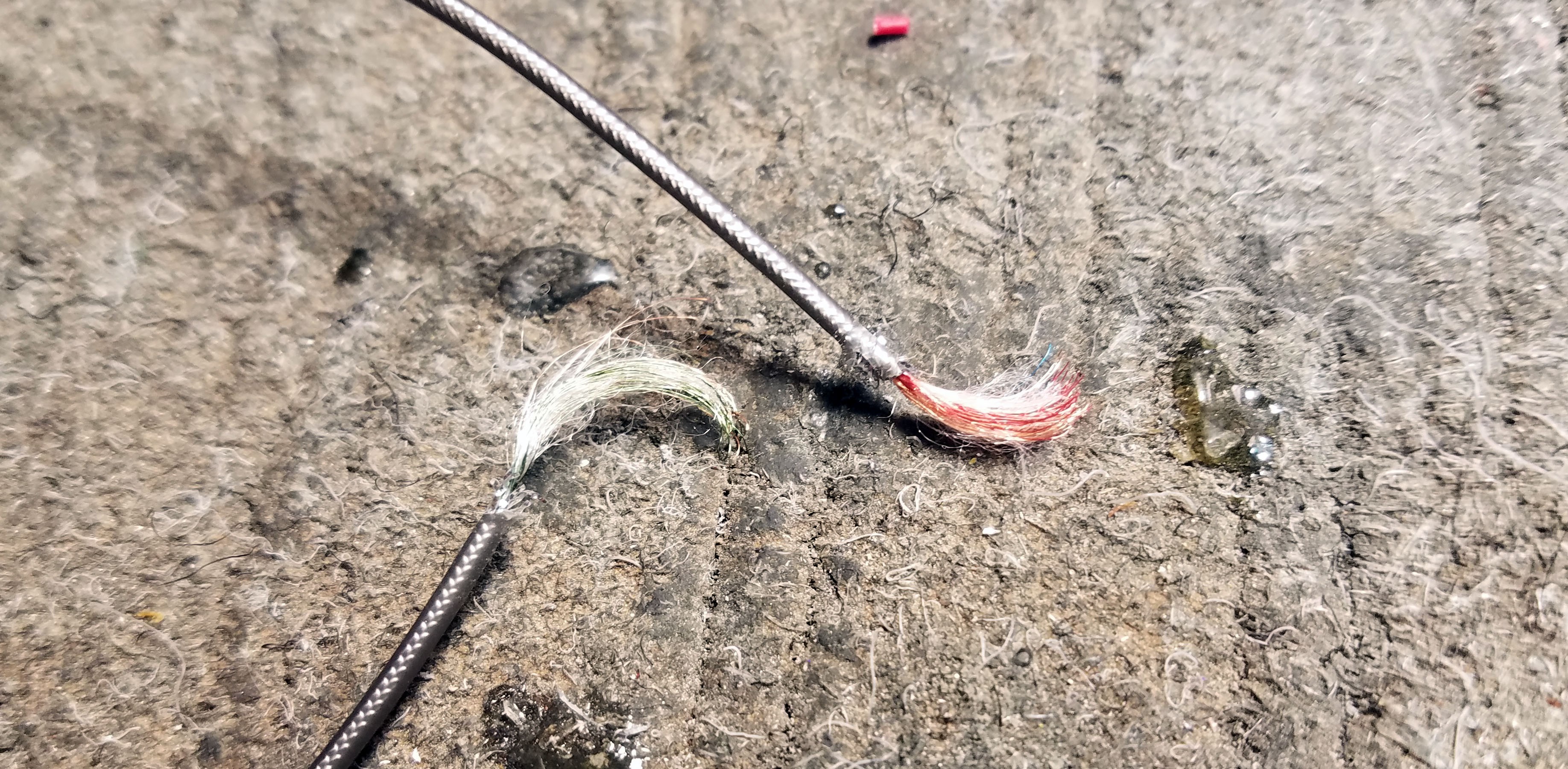
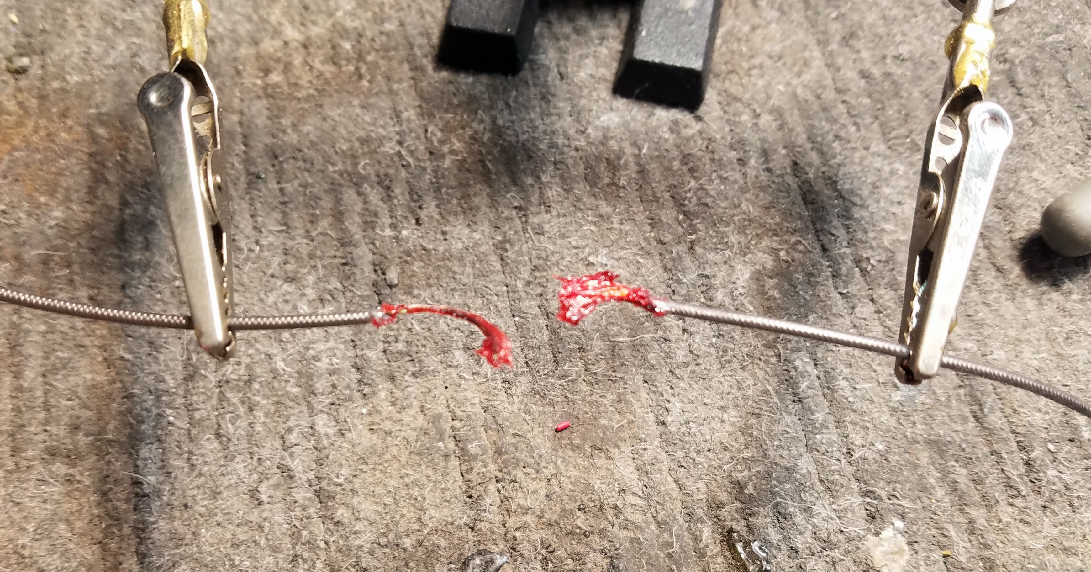
separating the enameled strands will make burning the enamel off a lot easier
![]()
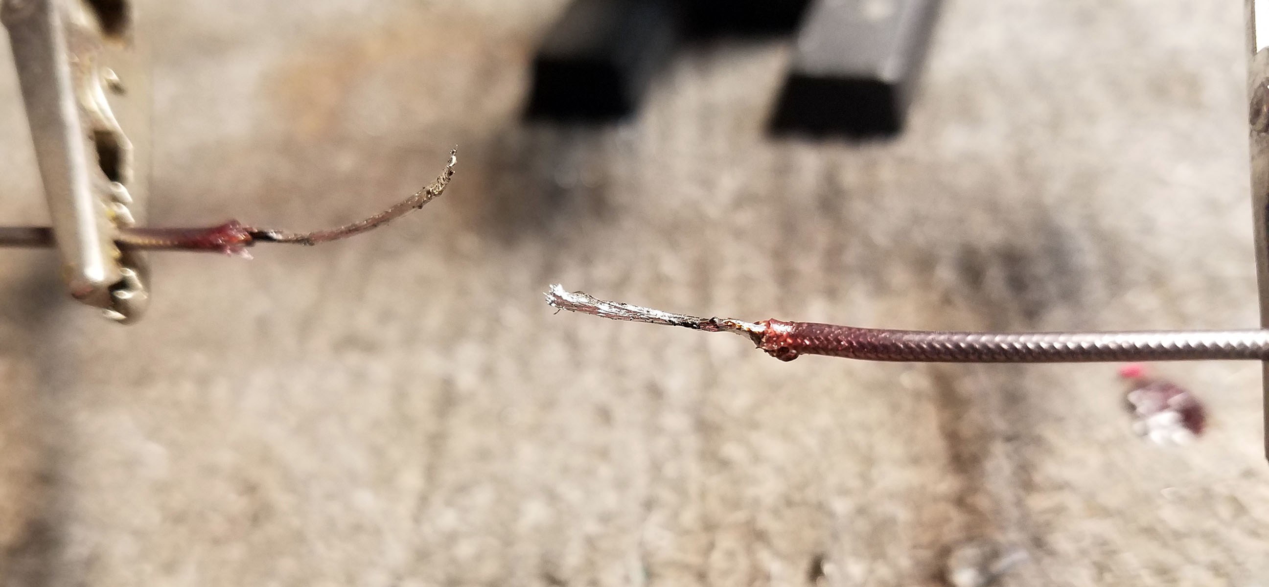
Completely cover all the strands with flux. I have found this to be pretty crucial when it comes to getting enamel off threaded audio cable.
![]()
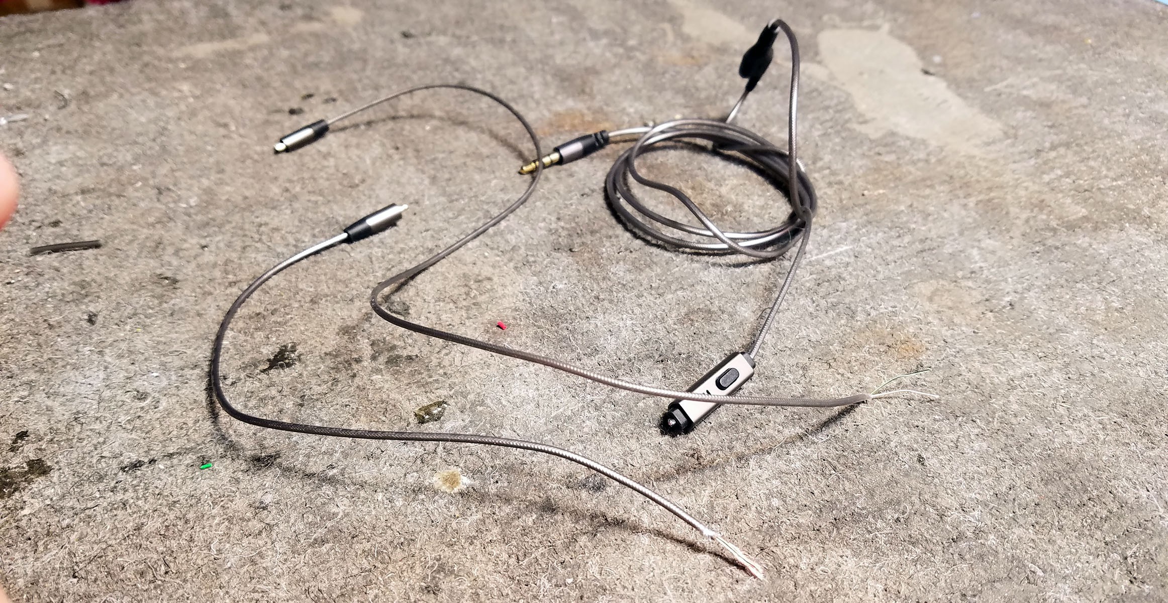
now those pesky enamel laden headphone cables will be easy to connect with electrodes
![]()
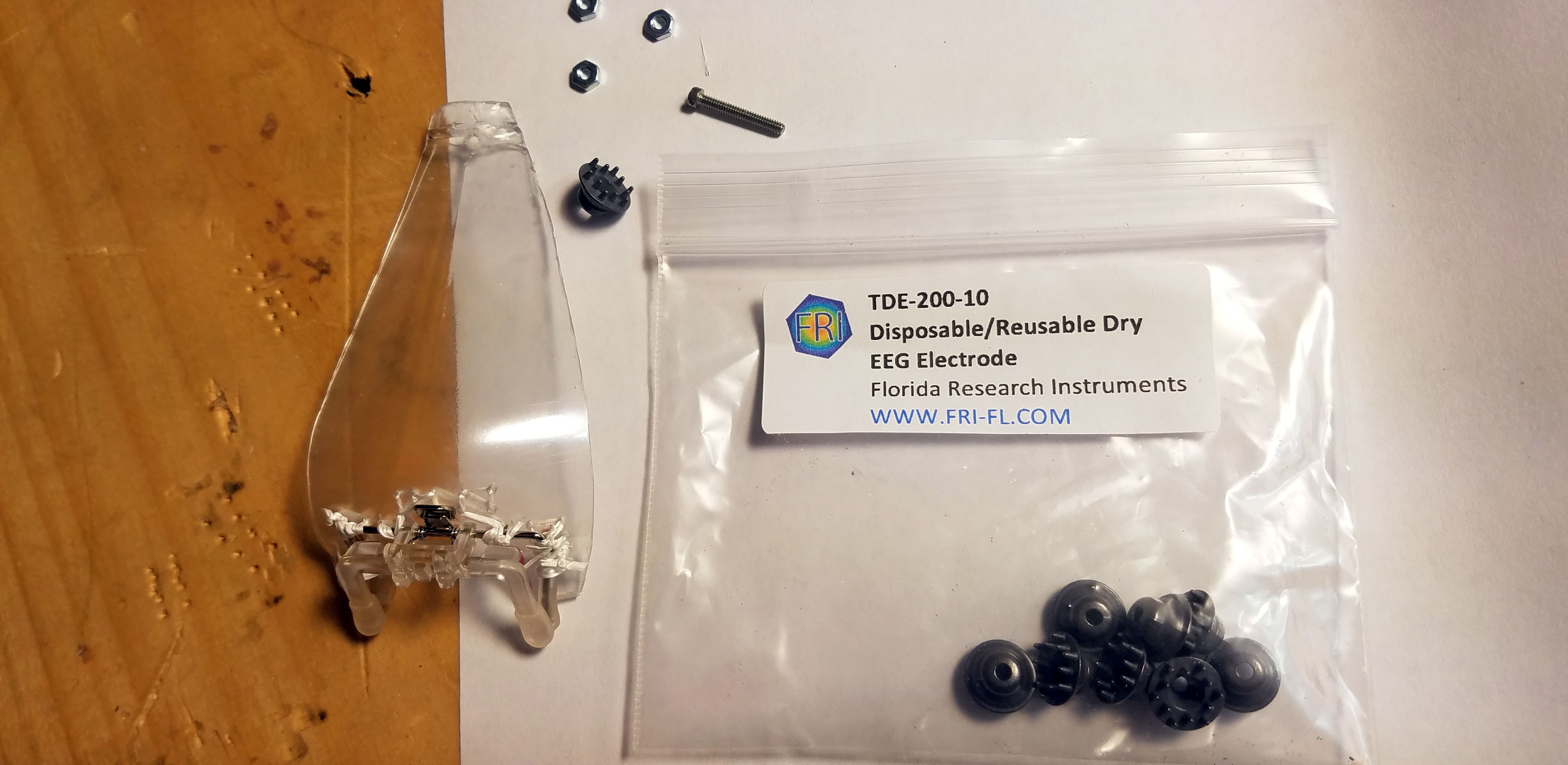
These are what the EEG dry electrodes look like. Above you can see the tiny bolt I use to attach to the plastic boom.
![]()
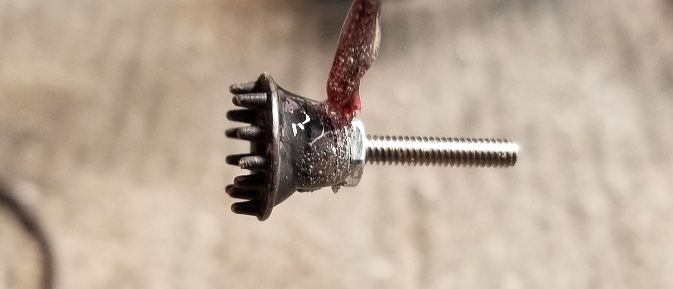
Cover everything with epoxy for strength and water resistance.
![]()
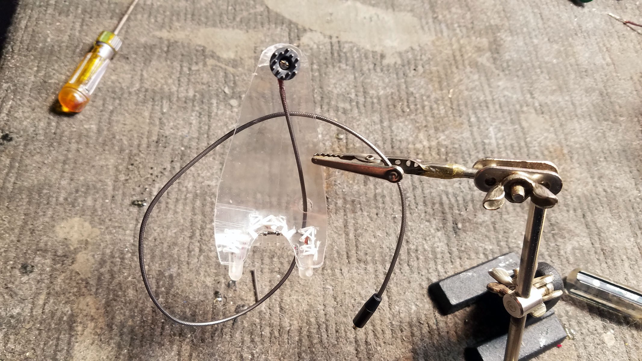
The screw shaft on the back of the finished electrode is inserted through a hole in the bottle plastic and affixed with a nut. I punch holes near the bottom of the clip-on boom for the electrode cable - this helps keep it from moving around and getting in the way of my eyes.
![]()
This is the front view. I left the bolt long for easy access but in hypothetical 'real life' this would be trimmed.
-
13Build Ear Reference Electrode
![]()
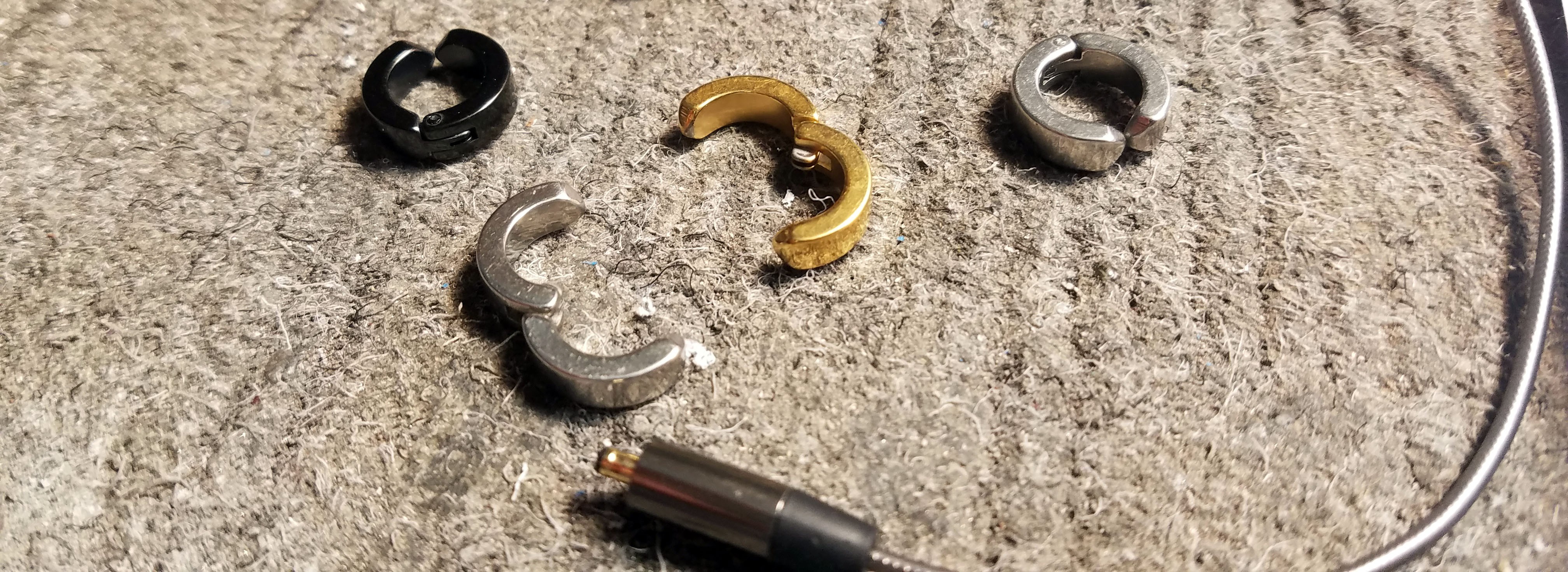
I used these great clip on earrings I found on Amazon as the foundation for my reference electrode (link in components list). They are sturdy and compared to other ear clip electrodes, very low profile.
![]()
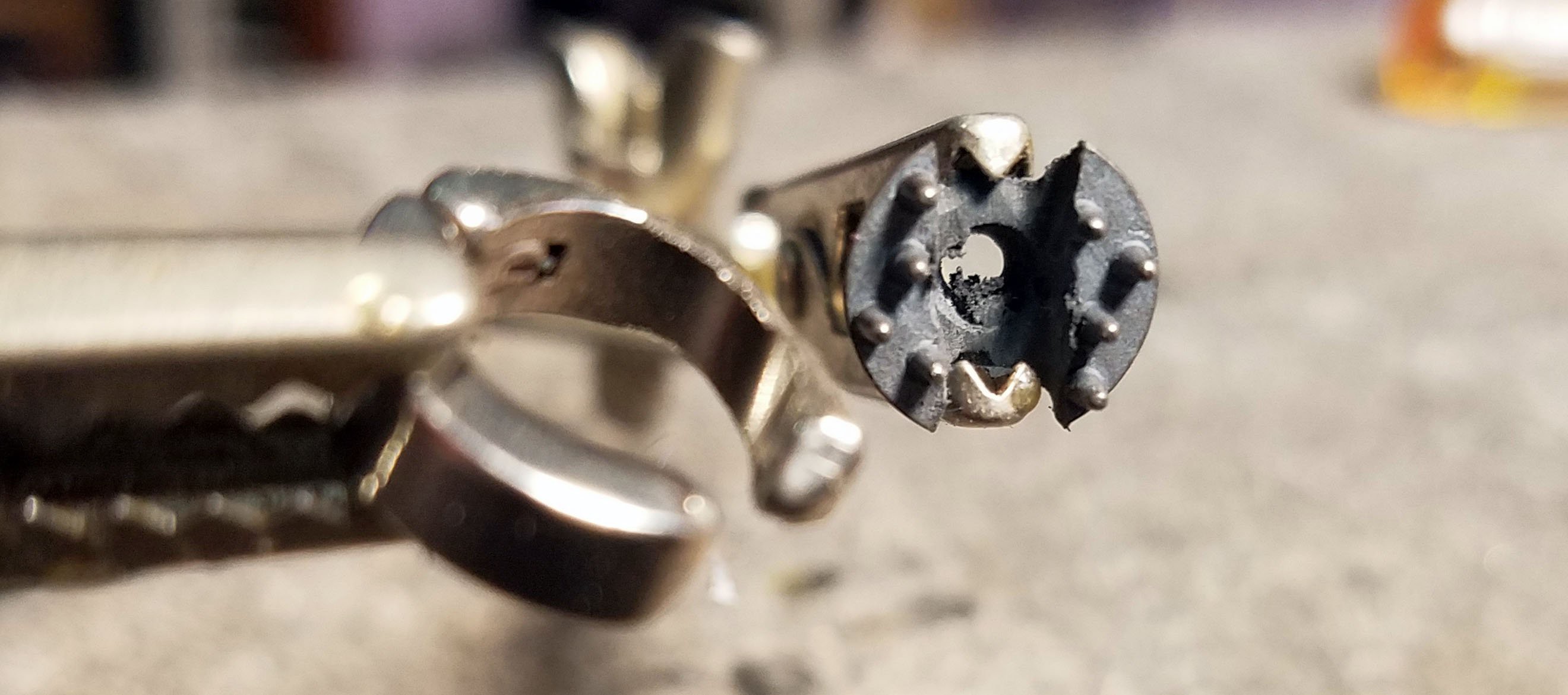
As with the frontal lobe sensing electrode, I used an off the shelf EEG dried electrode for reference. I used a Dremel rotary tool with a cut-off wheel to carve out a space in the electrode for the earring + slim down the earring so I didn't have to cut out too much of the electrode.
![]()
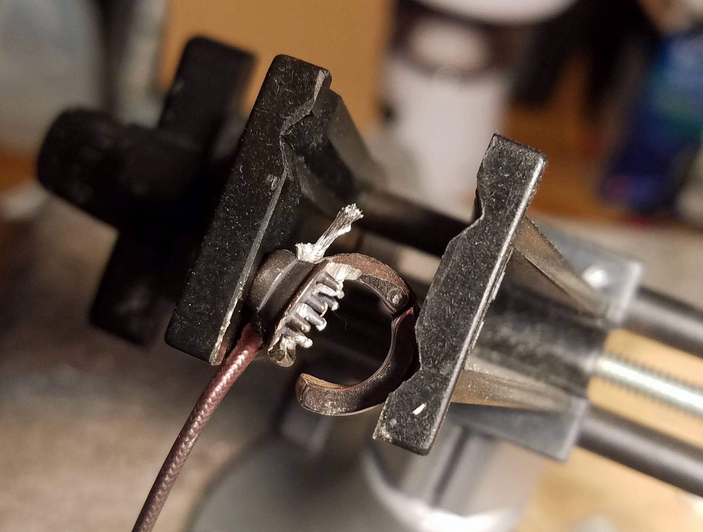
The pre-soldered tip of the headphone cable is sandwiched between the dry EEG electrode and the clip-on earring. Silver conductive epoxy takes a while to set, especially if you don't use heat, so a clamp or vice is probably best for this.
![]()
I used silver conductive epoxy to attached the pre-soldered head phone cable, EEG electrode and earring together. Then I covered everything in regular 5-minute epoxy for strength and electrical insulation. The cable attaching the electrode to the device can comfortably sit behind my ear which keeps everything more low profile.
-
14Install Plug For Programming and Spare GPIO Wires
![]()
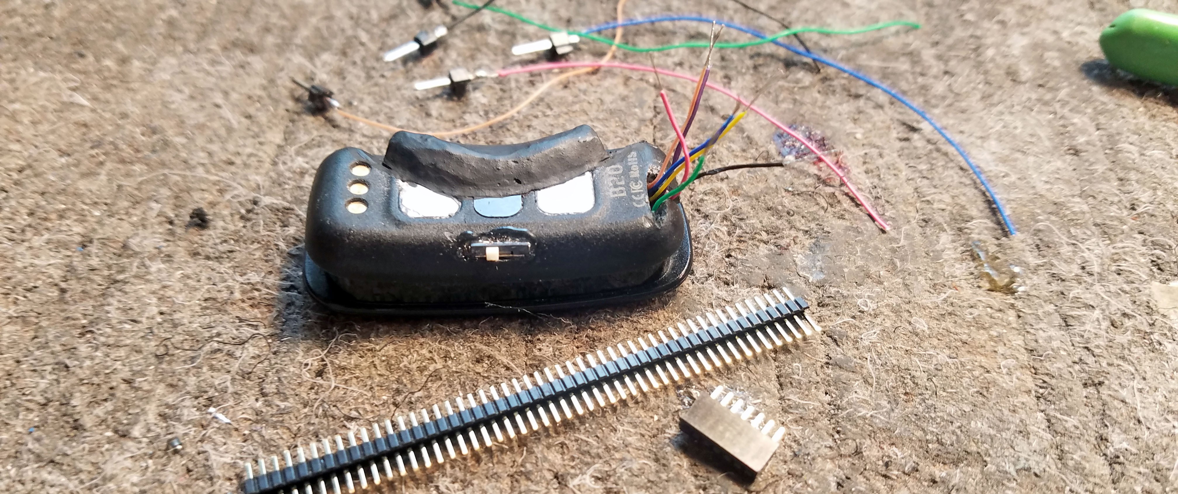
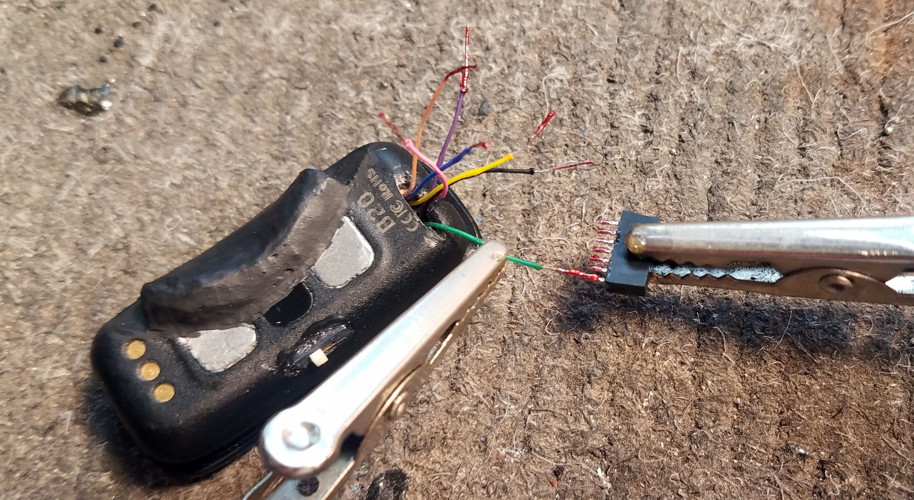
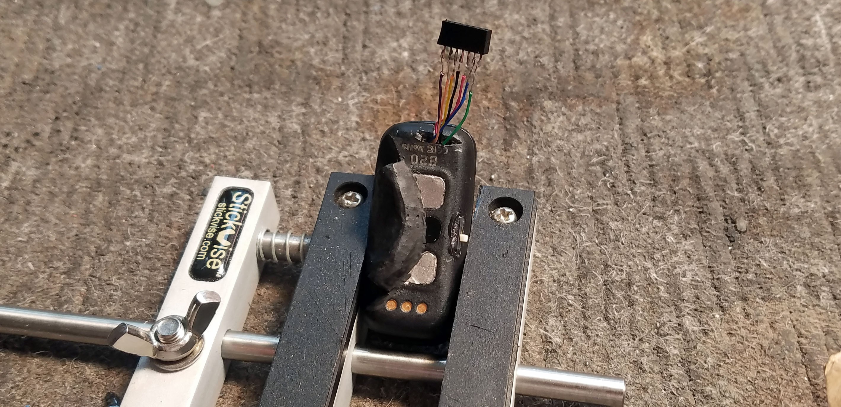
For little projects like this I usually just use header pins and header pin sockets for plugs. This way all those wire are out of the way while wearing the glasses but conveniently accessible when you need to program the device. The five fire are 1) V+ 2) GND 3) CLK for SWD 4) DIO for SWD 5) P25 6) P26 7) P10
![]()
I <3 flux
![]()
I always cover the base of the "plug" with epoxy, but be careful because its really easy leak excess epoxy inside which will cause a permanent jam.
-
15Alternate Electrodes
![]()
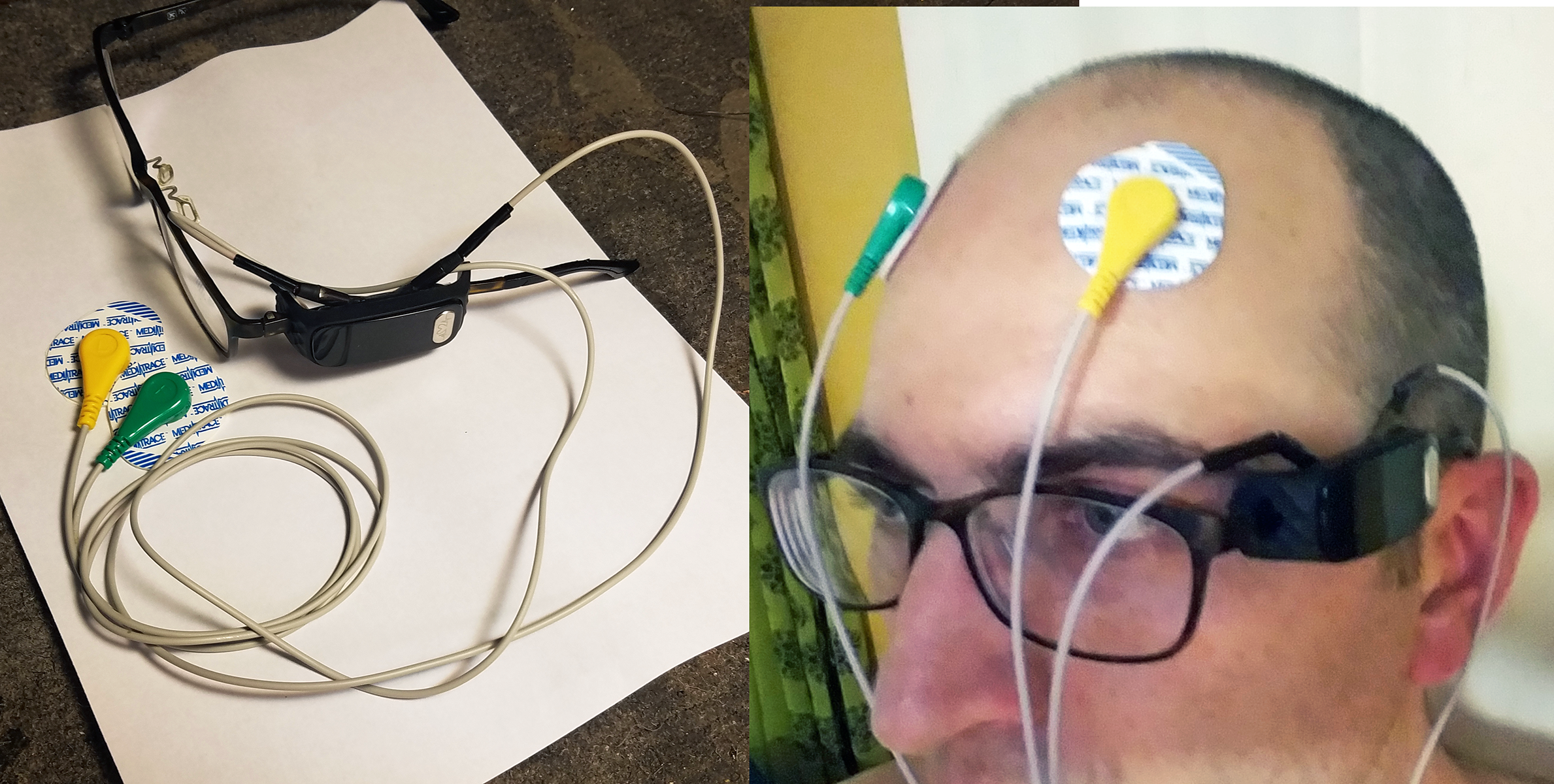
The primary reason I went to the trouble of installing plugs for the electrode cables was the ability to use a variety of electrode configurations. This way in addition to EEG I can use my hacked B20 fitness tracker for a variety of ECG and EMG experiments. Making things modular is also a nice way to isolate problems and ensure that the electrodes are functioning properly. The alternate electrodes pictured above are typical ECG disposable electrodes and electrode leads soldered to male plugs from another set of headphones.
-
16All Done, time for code!
![]()
EEG Glasses are all done, now you can go check out the code examples I wrote for the device and the companion data visualization and machine learning website.
Hacking a $35 ECG nRF52 Fitness Tracker into EEG
nRF52832 ECG fitness tracker hacked into EEG glasses using Arduino code + detect concentration/relaxation with neural network web app
 Curt White




Discussions
Become a Hackaday.io Member
Create an account to leave a comment. Already have an account? Log In.
Great work man! I'll just order this hardware today! I've done some custom PCB using the 8 channels ADS1298 but its a quite expansive IC. Want to do some experiments using this cheaper option. By the way, I was taking a look at the datasheet, and saw you have two differential channels, right?
You said it uses the RLD as your reference electrode. It means you could get up to 3 more channels, being two of them a reference and two as positive inputs, right?
Could you track the circuit of this electrodes configuration? I'm wondering to use more than a single channel, but not sure if will need to make major modifications in the hardware. If they designed on all negative inputs grounded you still could get two channels. But if they used one of the channels as reference instead of an actual RLD it would be bad for my design.
Are you sure? yes | no
No, RLD is used for reference so you won't have to worry about that. I did contemplate trying to break out the second channel on the ADS1292. My priority was to get frequency domain signal processing working on the device itself (on the nRF52 MCU). Just processing one channel required a lot of compromises, two channels would be a nonstarter as far as I can tell. If you are processing the data elsewhere (like most people) the computational overhead makes no difference and the more channels the merrier. You'll have to cut PCB traces and solder directly to the pins on the ADS1292. Tricky, but doable. Let me know if you take a crack at it, it sounds interesting.
Are you sure? yes | no
Great to know! I'm waiting for shipping right now. I'll definitely give a try and let you know. I believe I'll also try to migrate the firmware IDE to keil, my goal is to install a RTOS and use CMSIS libraries to do the filtering, I've never tried those libraries yet and seems to be pretty fast, considering they were designed by ARM itself. As soon as I have some progress let you know!
Are you sure? yes | no
Of course. Serial works the same on the nRF5x Arduino Core as it would on an actual Arduino. All the code example for this project (EEG/ECG) use serial debugging so you can use that as a guide.
ID107 (nRF51822) or ID107Plus (nRF52832)? I'll assume the first but it doesn't really make a difference. The key thing is the variant.h file. Here is a link to the ID107 variant file in the main project repo: https://github.com/curtpw/nRF5x-device-reverse-engineering/blob/master/ID107-nrf51822-activity-tracker/firmware/sandeep_arduinocore_variant/Childmind-nrf51-D3/variant.h
Look at these lines in the code:
// Serial
#define PIN_SERIAL_RX (17)
#define PIN_SERIAL_TX (18)
you need to make sure the Serial TX definition matches up with whatever GPIO on the nRF52822 you've decided to use for sending over serial.
Are you sure? yes | no
Hi Curt, great work. Do you have a an example code with Ble serial to run on ID107HR fitness tracker.
Are you sure? yes | no