-
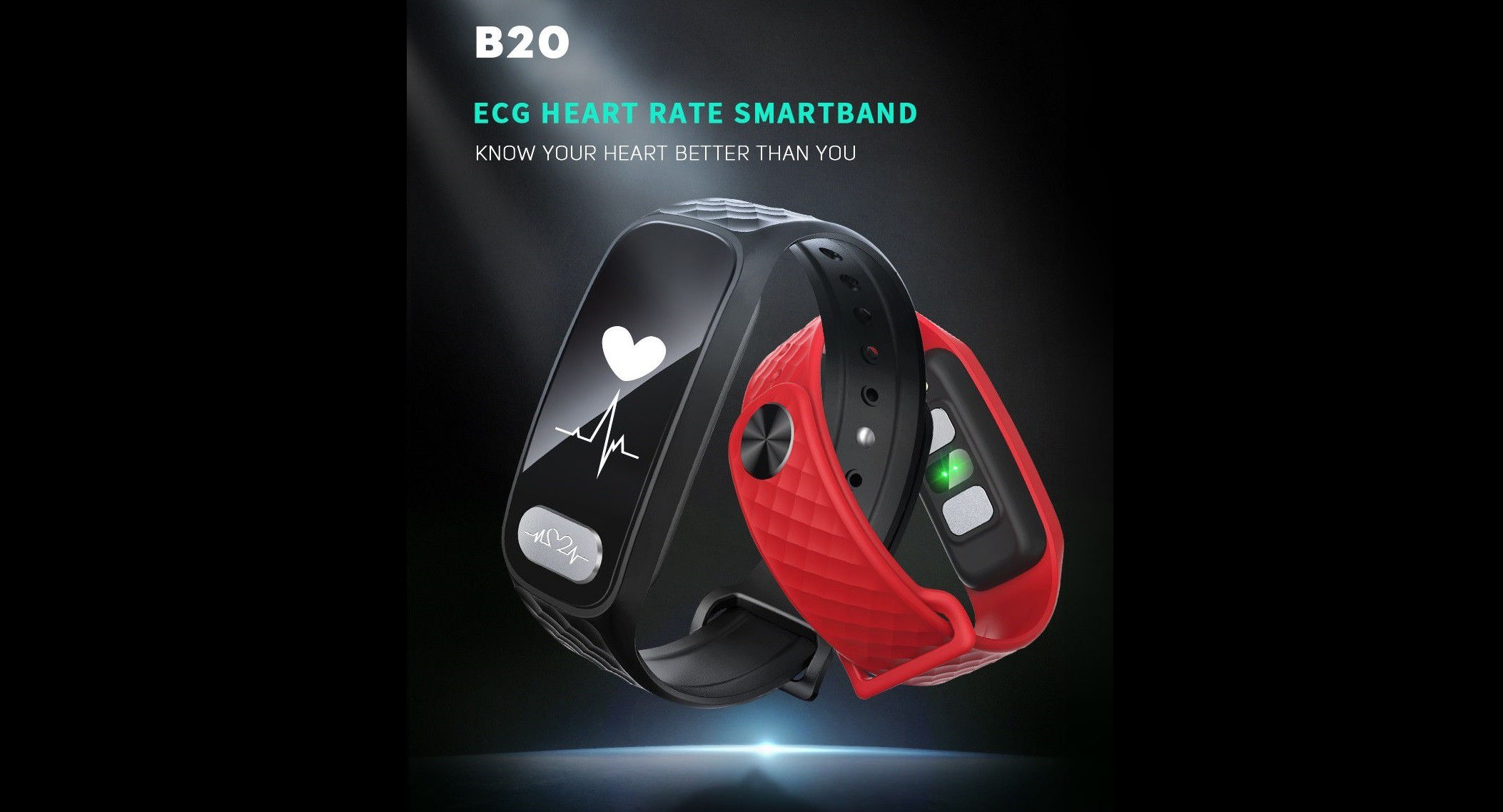
1Acquire a B20 ECG Fitness Tracker or Comparable
First thing first, you need to get the materials. Here are some links for purchasing the B20:
- https://www.amazon.com/Bozlun-Pressure-Pedometer-Distance-Waterproof/dp/B074K9D97B
- https://www.aliexpress.com/item/Slimy-B20-ECG-Heart-Rate-Blood-Pressure-Monitor-Smart-Band-Bluetooth-Fitness-Bracelet-Smart-Wristband-Watch/32836720008.html
- http://www.globalsources.com/gsol/I/Smart-watch/p/sm/1154438131.htm#1154438131
- https://www.dhgate.com/product/b20-smart-bluetooth-ecg-ppg-health-bracelet/409064543.html
- https://www.skmei-watch.com/index.php?route=product/product&product_id=927
- http://www.dx.com/p/eastor-b20-ecg-heart-rate-blood-pressure-monitor-smart-band-red-479559#.W3x7iuhKiUk
- https://www.aliexpress.com/item/Slimy-B20-ECG-Smart-Band-Heart-Rate-Blood-Pressure-Monitor-Bluetooth-Fitness-Bracelet-Smart-Wristband-Watch/32850321098.html
![]()
There are a bunch of other inexpensive Chinese fitness trackers with both an ADS1292 ECG chip and a Nordic nRF52832 SoC. Be careful to select the right one, or even better, hack a different model and add your work to the project GitHub repo.
You can also run all the code posted for this project with an Arduino compatible microcontroller and an ADS1292 breakout like the one offered by Protocentral.
-
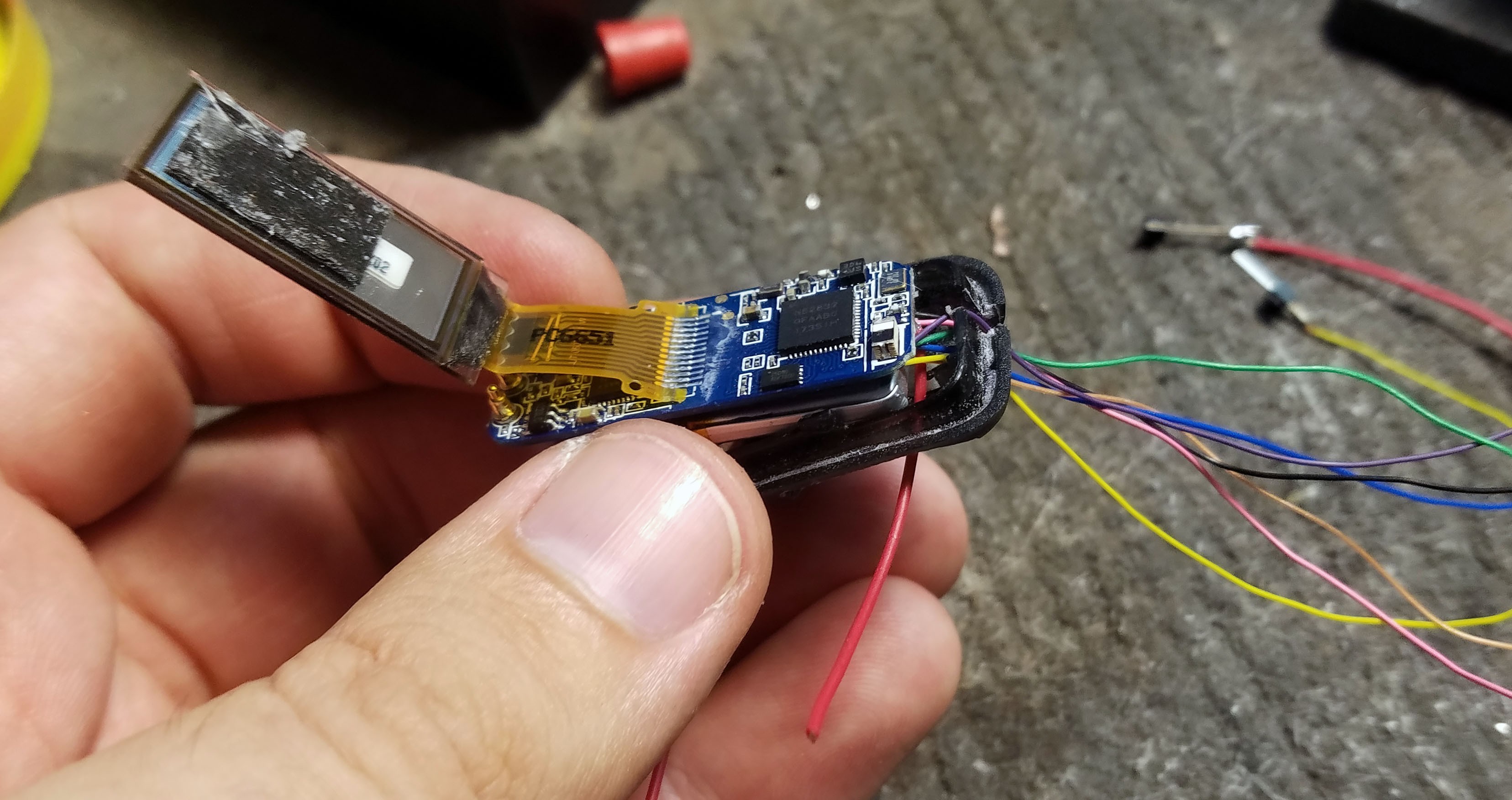
2Disassemble the B20 and Solder Wires for Programming and Serial Data Transfer
![]()
For instructions on actually programming the device, see the project GitHub repository README: https://github.com/curtpw/nRF5x-device-reverse-engineering and videos from this project which also involves hacking Nordic nRF52832 MCU based fitness trackers: https://hackaday.io/project/144350-hacking-wearables-for-mental-health-and-more
-
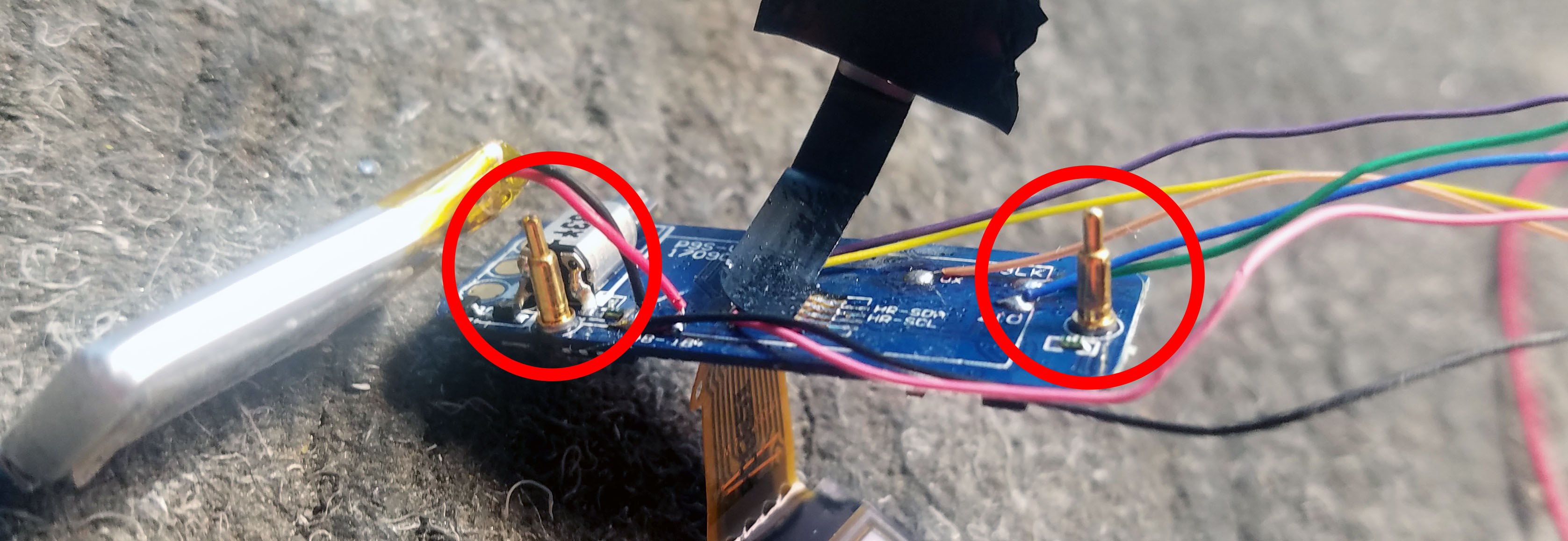
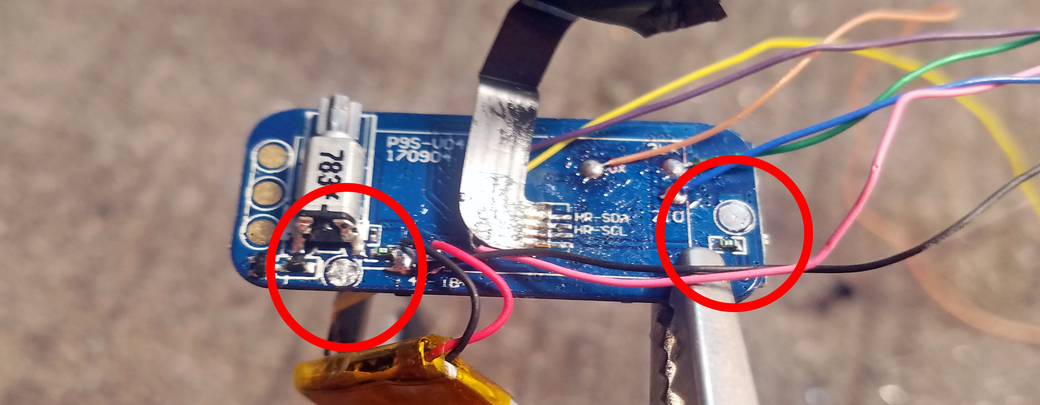
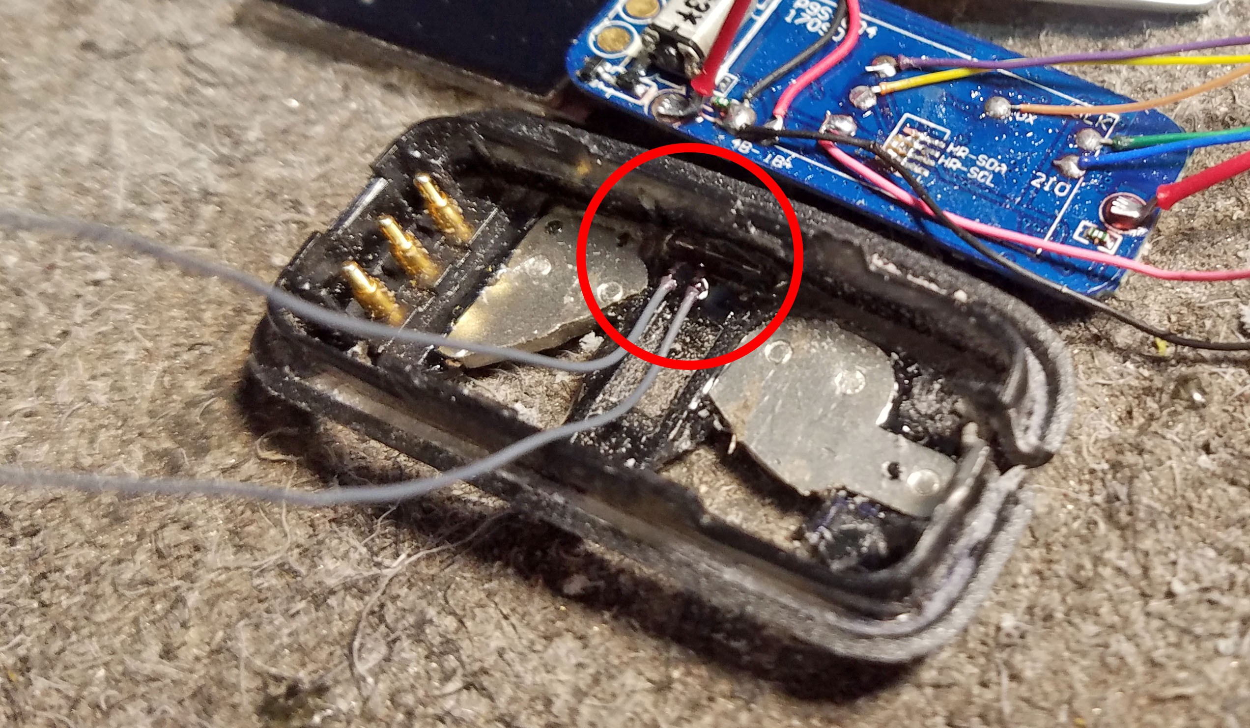
3Desolder Channel 1 and Right Leg Drive Spring Pins
![]()
The spring-loaded pogo pins connect to the two meta plates/electrodes at the bottom of the unmodified fitness tracker enclosure.
![]()
Those big pogo pins suck up a lot of heat so you'll have to leave your iron sitting next to them for a couple seconds. Make sure you don't accidentally de-solder anything else.
-
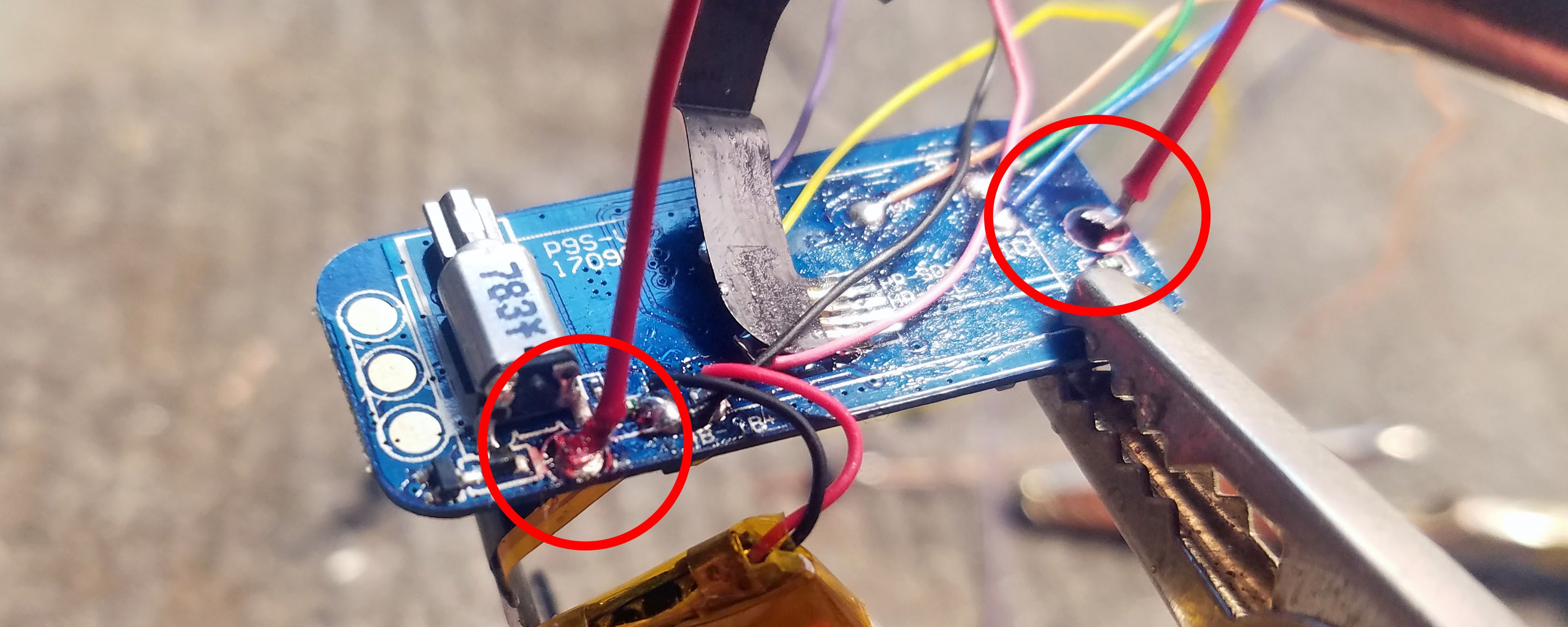
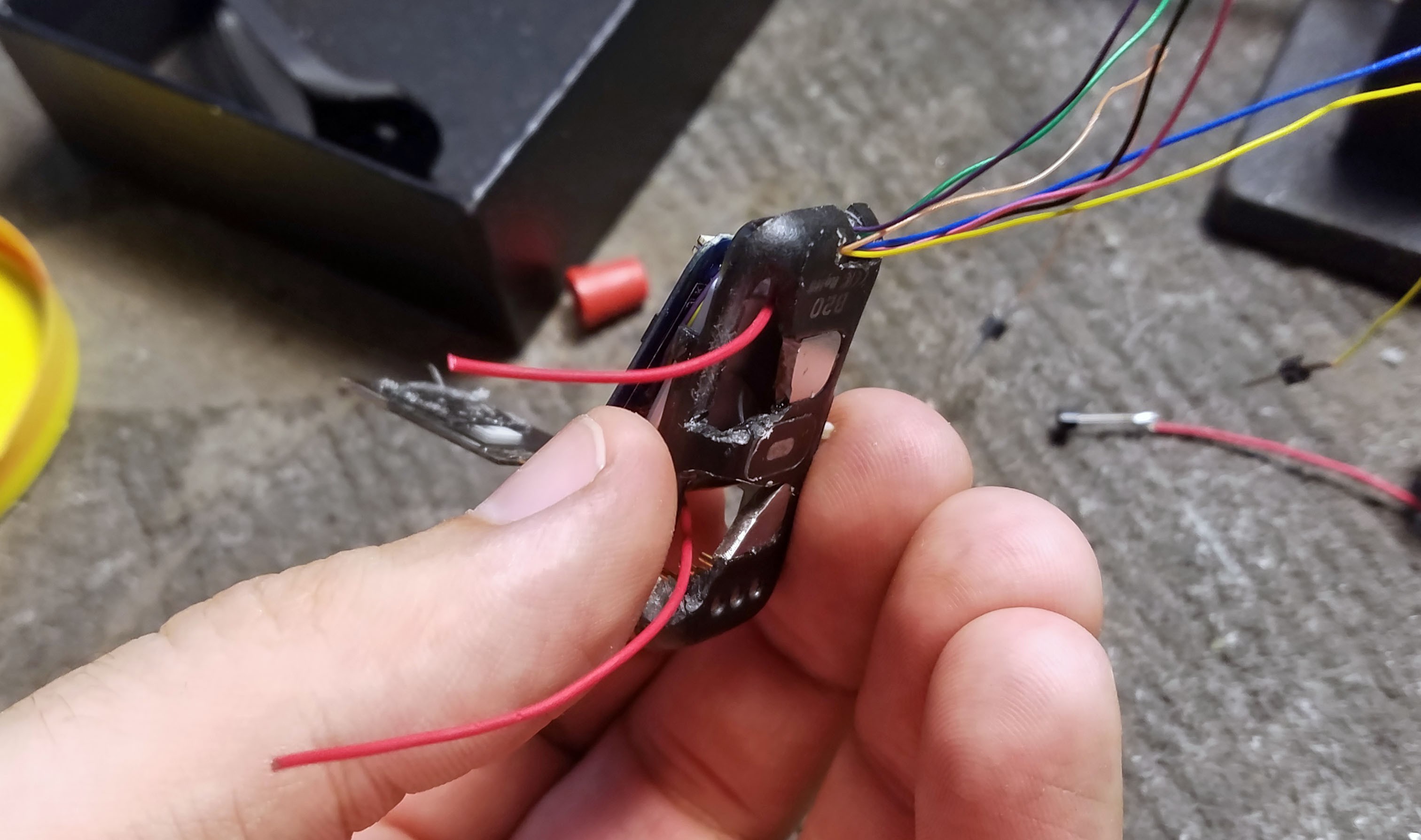
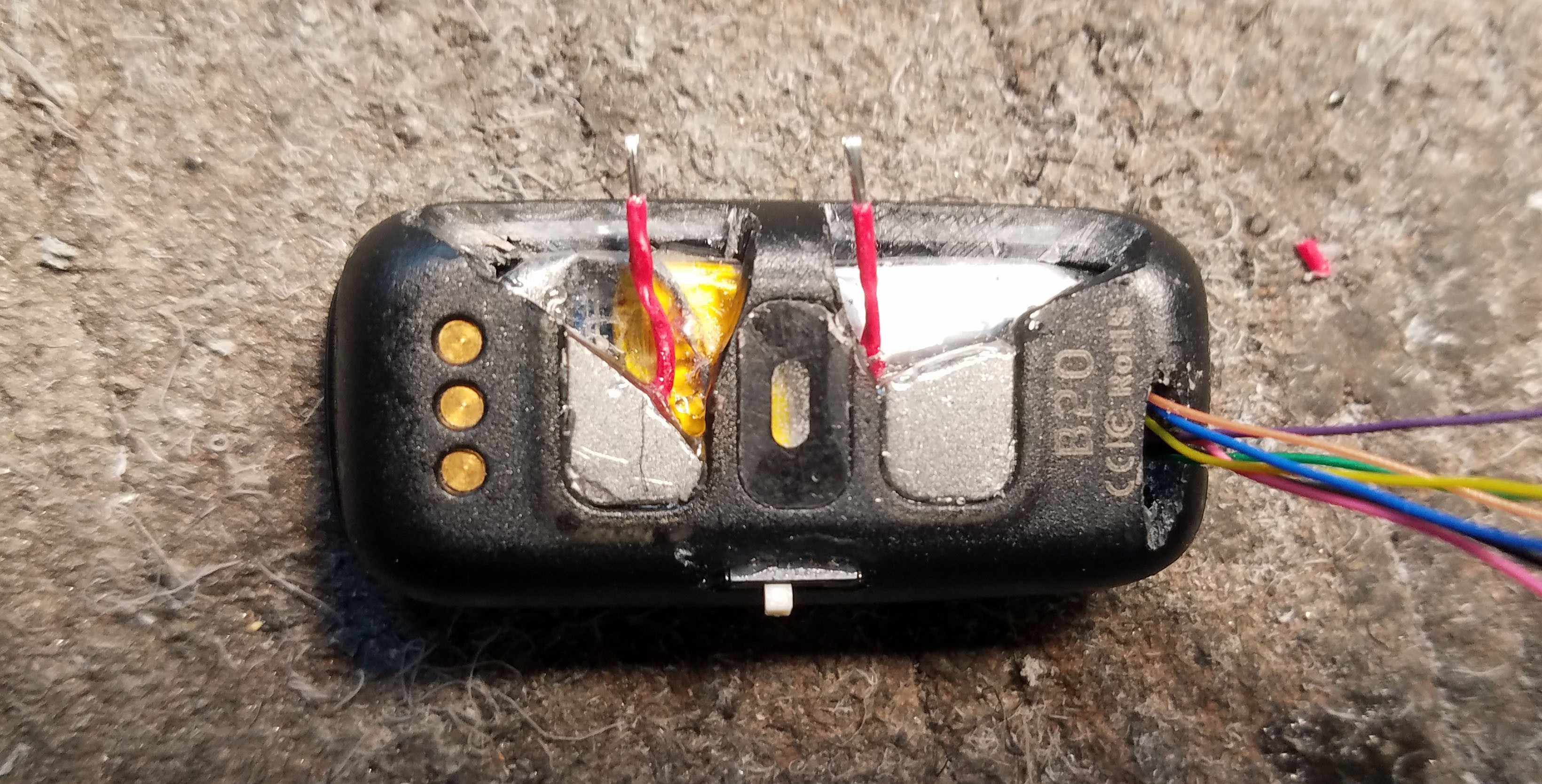
4Solder Lead Wires to Channel 1 and Right Leg Drive Solder Pads
![]()
I used fairly large wire for the electrode leads with lots of surface contact when soldering to the pads.
-
5Trim and Punch Holes Through Wrist Band to Fit on Glasses
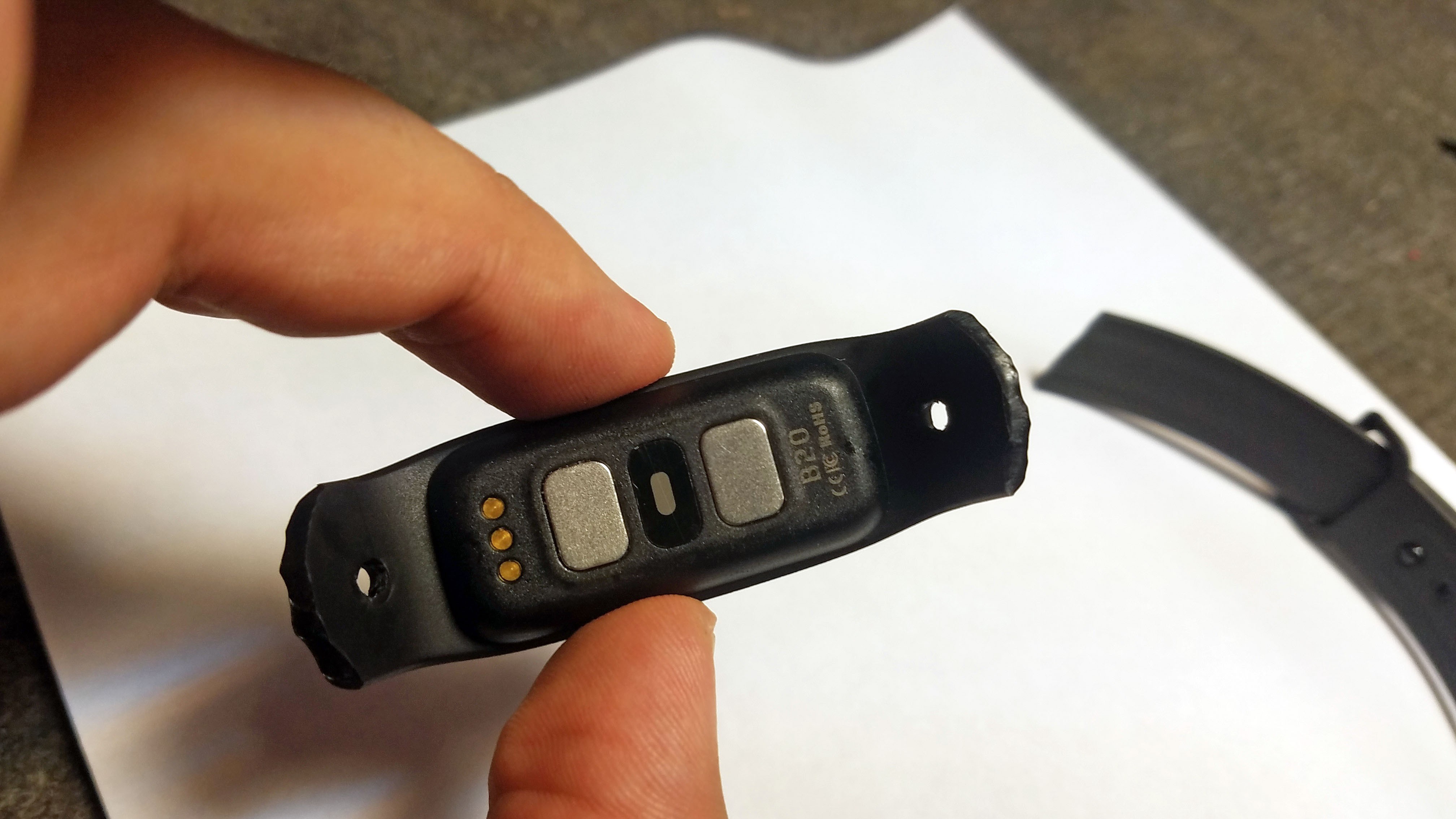
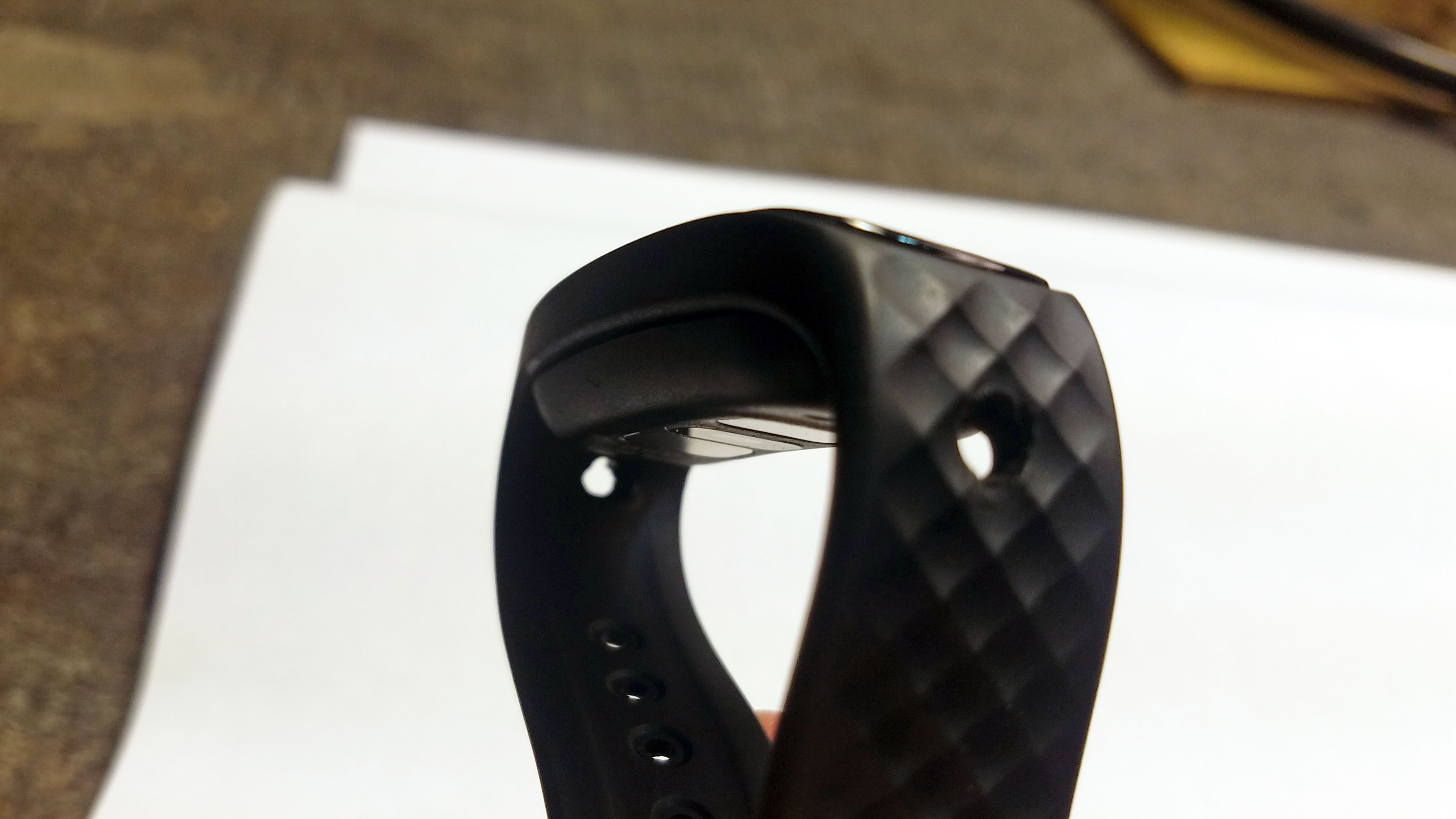
This will probably have to be customized for individual glasses, but I'm sure all kinds of variations are possible. This just happened to be easiest for me.
![]()
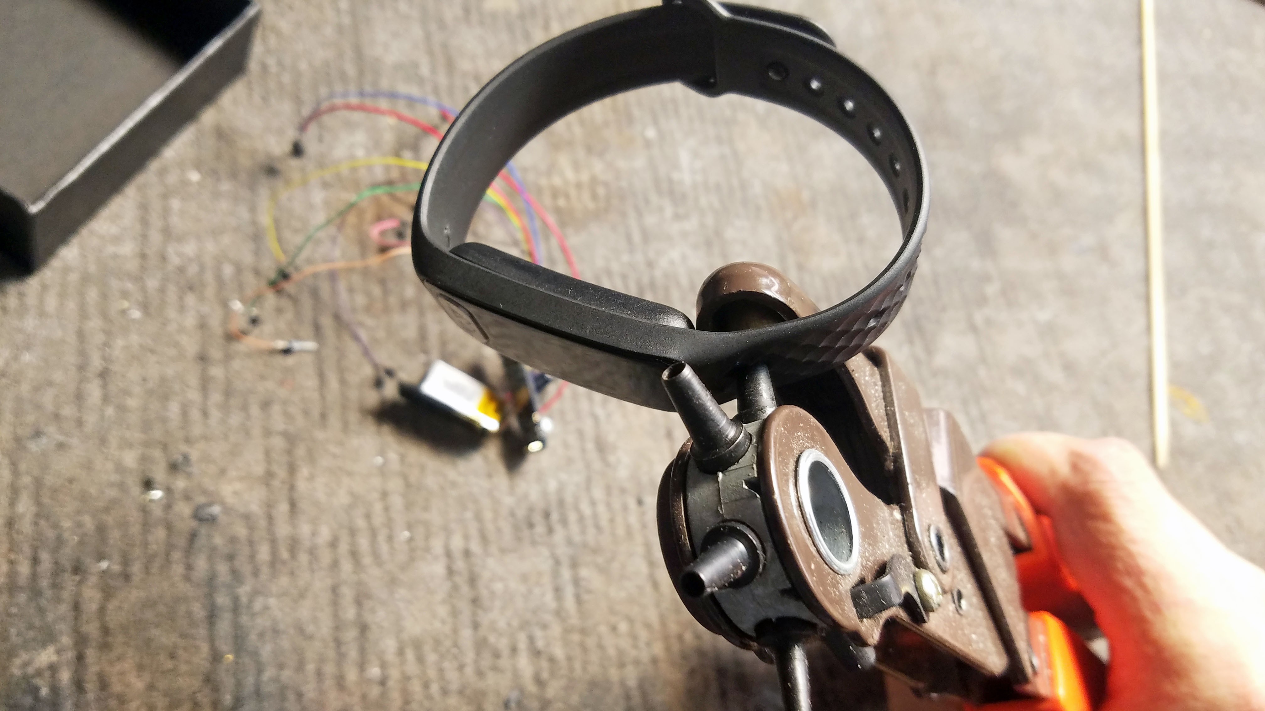
There are many ways to put holes in things. This one worked for me.
![]()
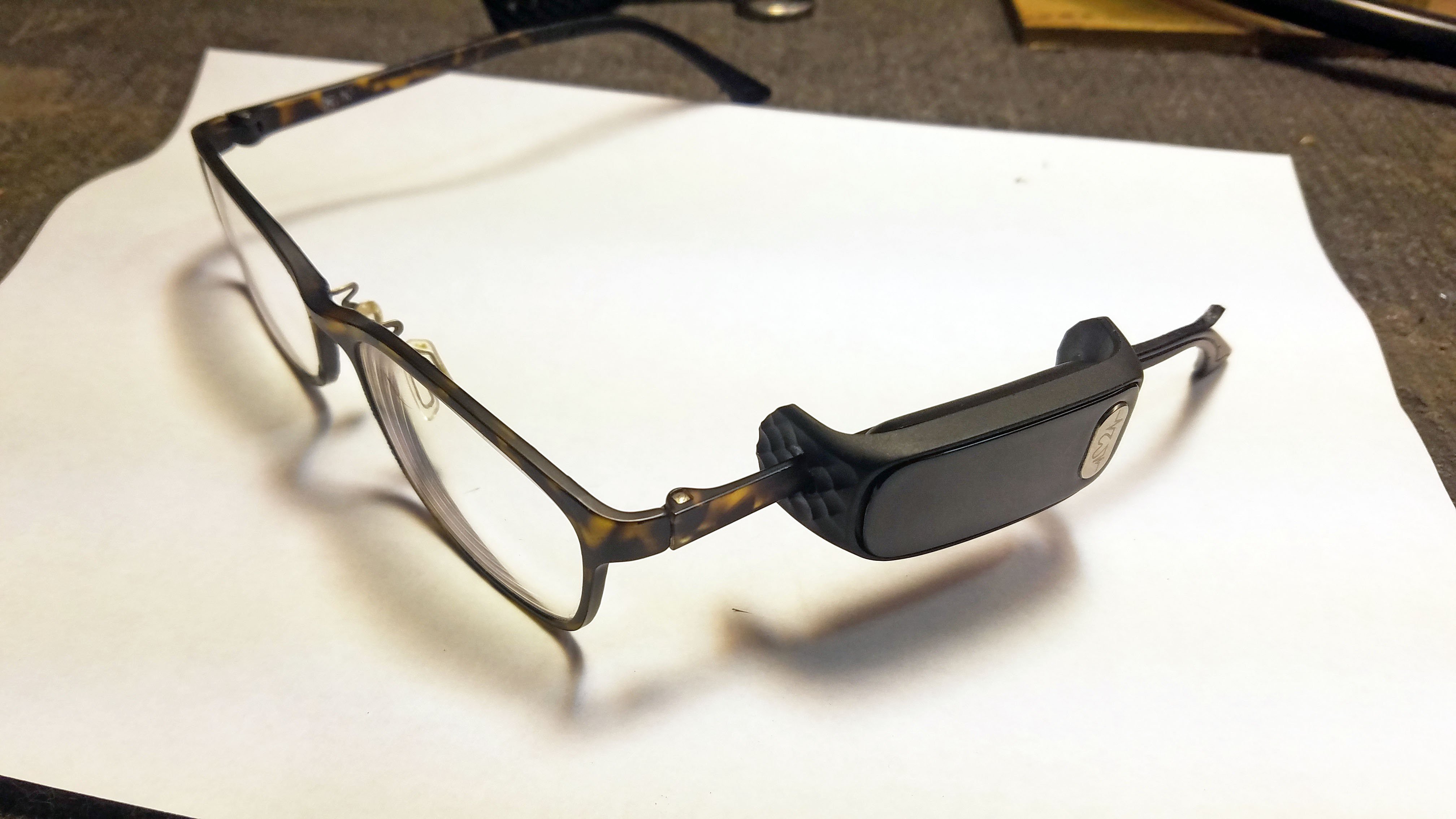
The legs of my glasses got in the way of charging with the fitness tracker body installed, but since the electrode leads are modular with convenient plugs its easy to just pull the fitness tracker body out of the rubber strap for charging.
![]()
![]()
This is actually quite comfortable with a little adjusting. It is completely out of the way of my face.
-
6Extract Miniature Audio Plugs from Ear Buds and Prep For Use As Electrode Lead Plugs
![]()
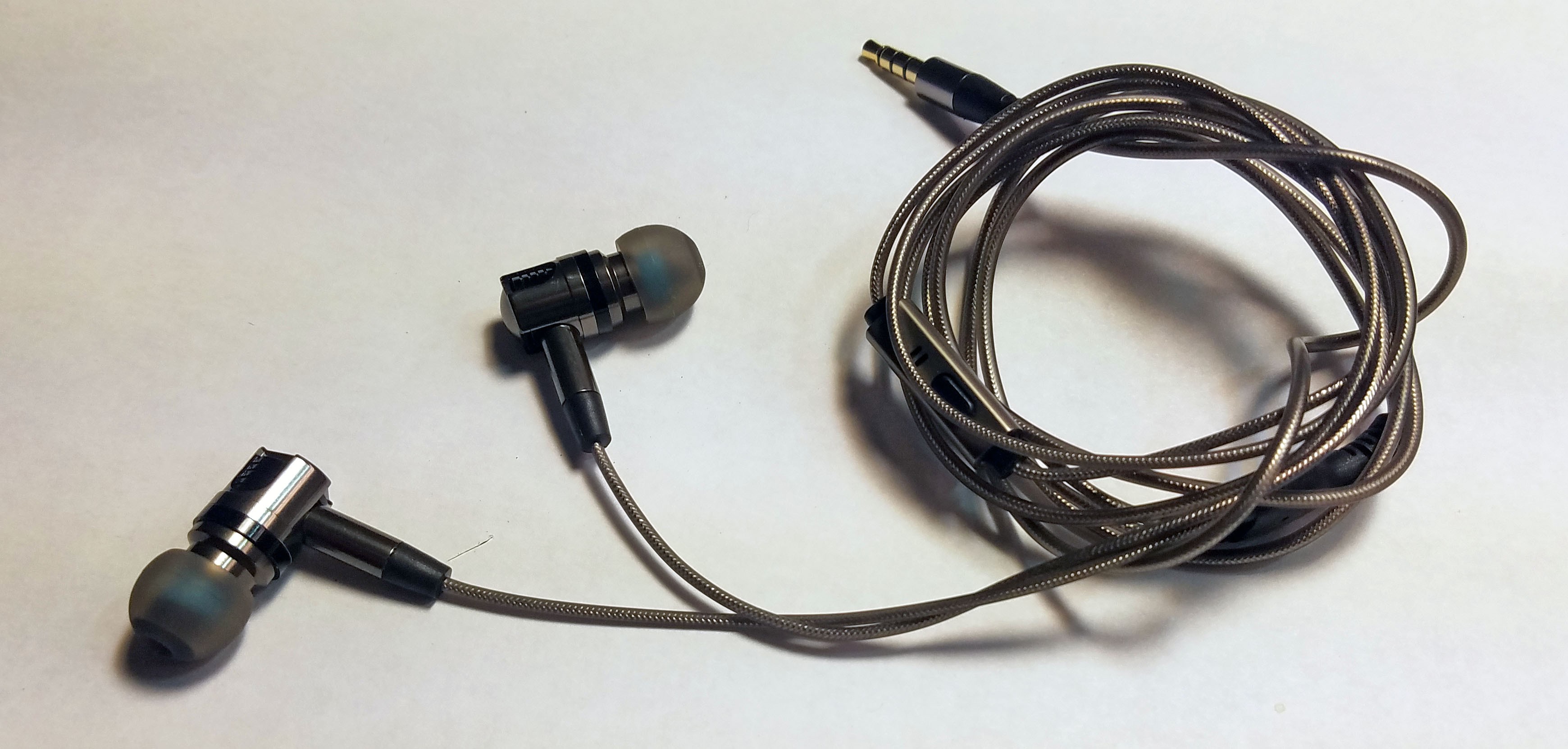
Yup, I used earphones.
![]()
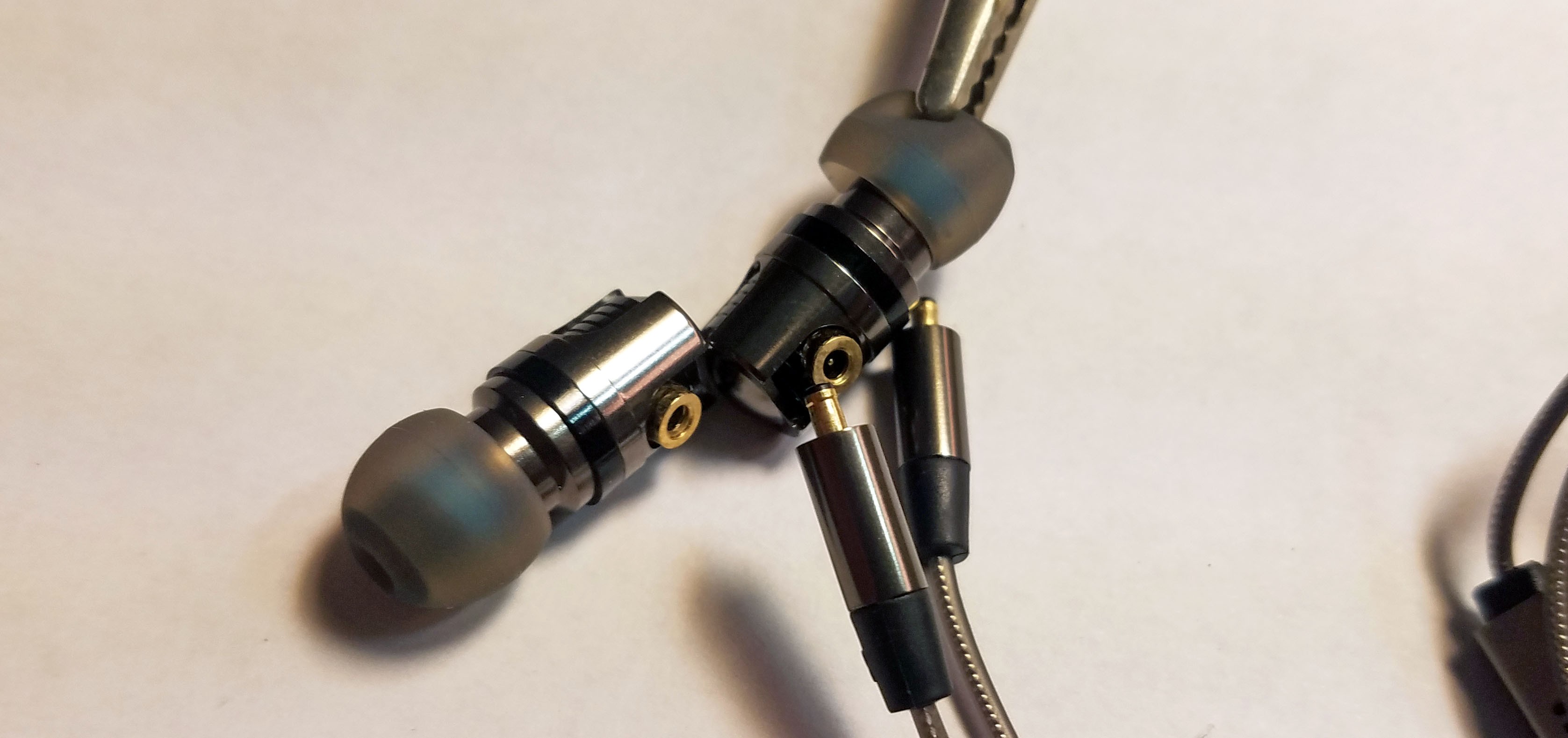
I was looking for plugs and couldn't find any I likes. Then I found these earphones and didn't look back. They work quite well.
![]()
This pulls right off.
![]()
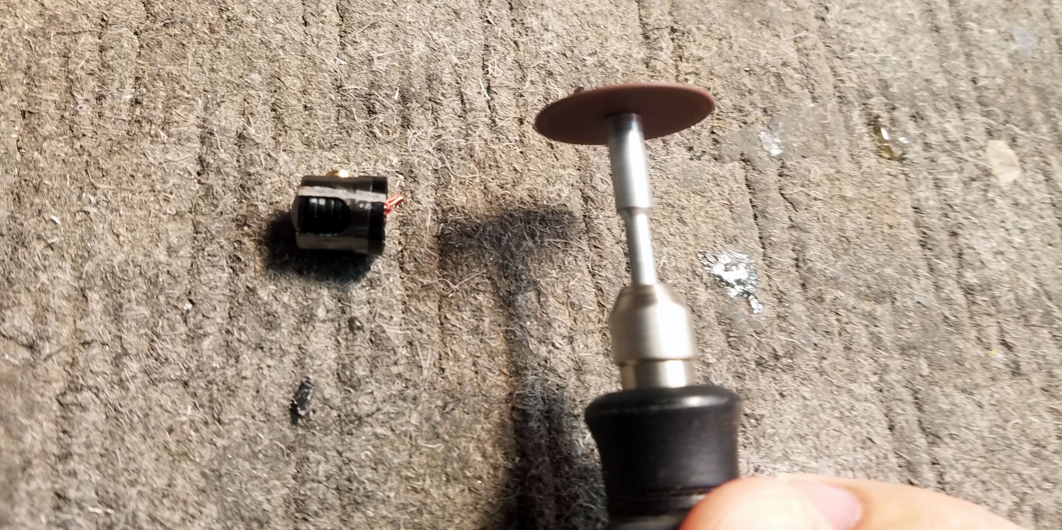
There is a chance I could have done this without a Dremel cut-off wheel but I didn't want to take any chances.
![]()
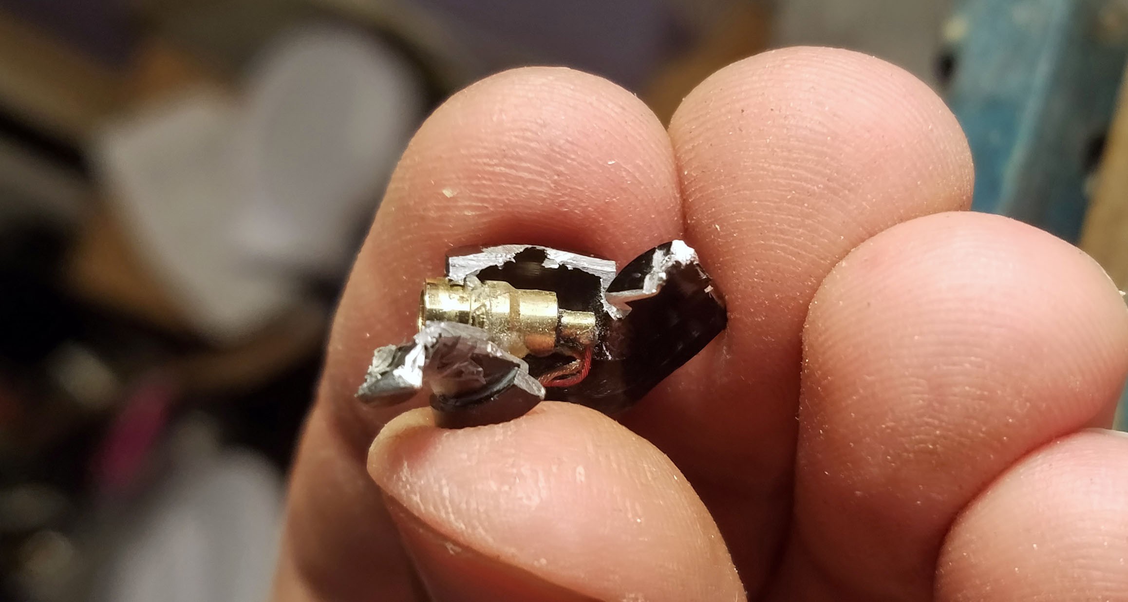
Female end of the plug epoxied to what remains of the aluminum earbud enclosure.
![]()
Ready for installation
-
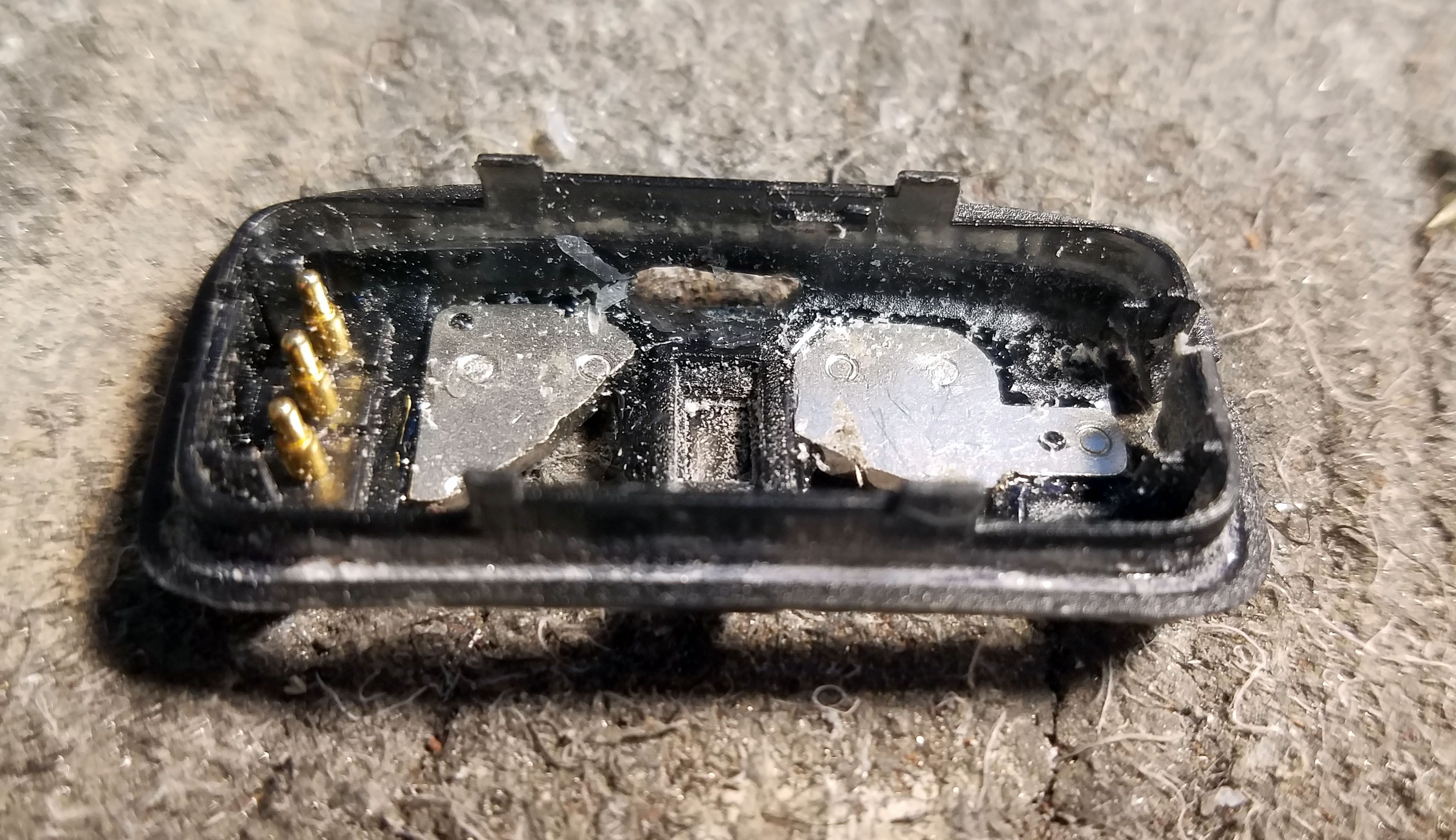
7Carve Out Holes in the Enclosure for Electrode Plugs, Programming Wires and SMD Switch
![]()
This really does require a Dremel.
![]()
![]()
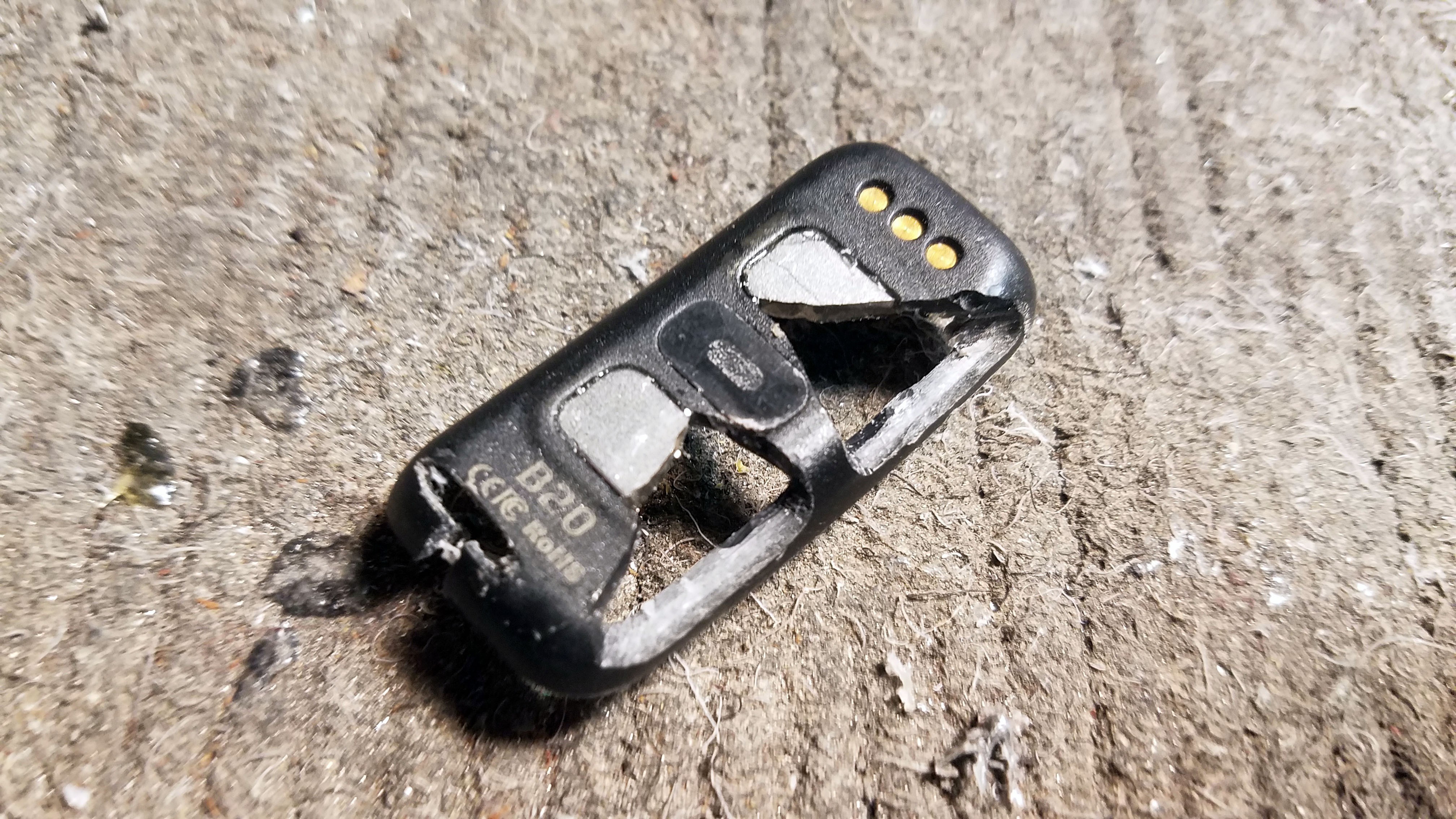
4 holes:
1) Electrode plug 1
2) Electrode plug 2
3) Programming/GPIO wires
4) Switch
-
8Install the Power Switch
![]()
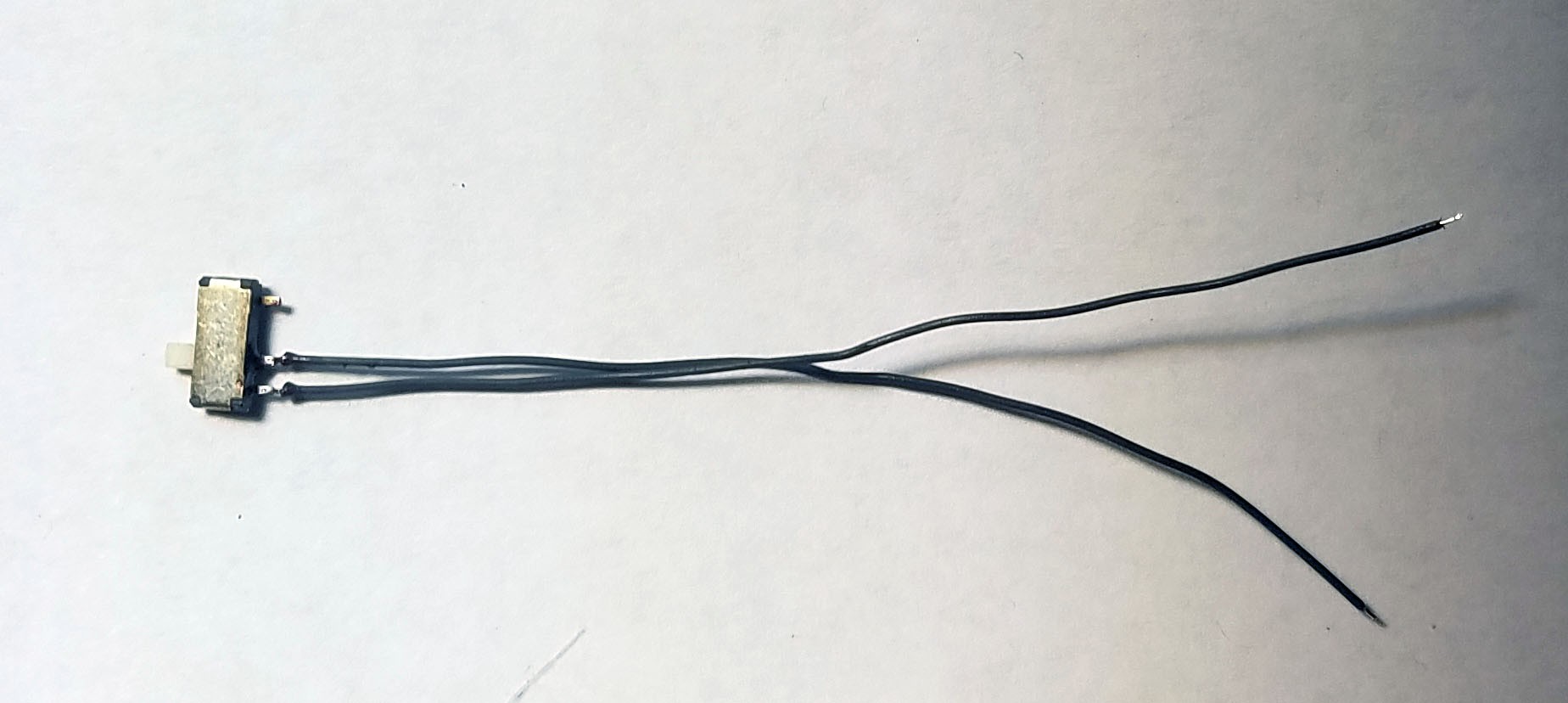
These little SMD switches are handy. I solder wires onto them before installing.
![]()
I epoxy the switch in place, being careful not to jam it with excess epoxy.
-
9Mount PCB In Modified Enclosure
![]()
Fitting all the wires in their assigned holes....
![]()
![]()
I trim down the electrode wires for soldering. Test to see if everything fits inside the enclosure when the cap is fixed on top. The cap and enclosure body should fit together without any pressing or pushing. I had to adjust the position of the battery inside the enclosure to get a good fit.
-
10Mount EEG Electrode Plugs on Enclosure, Finish With Bondo and Paint
![]()
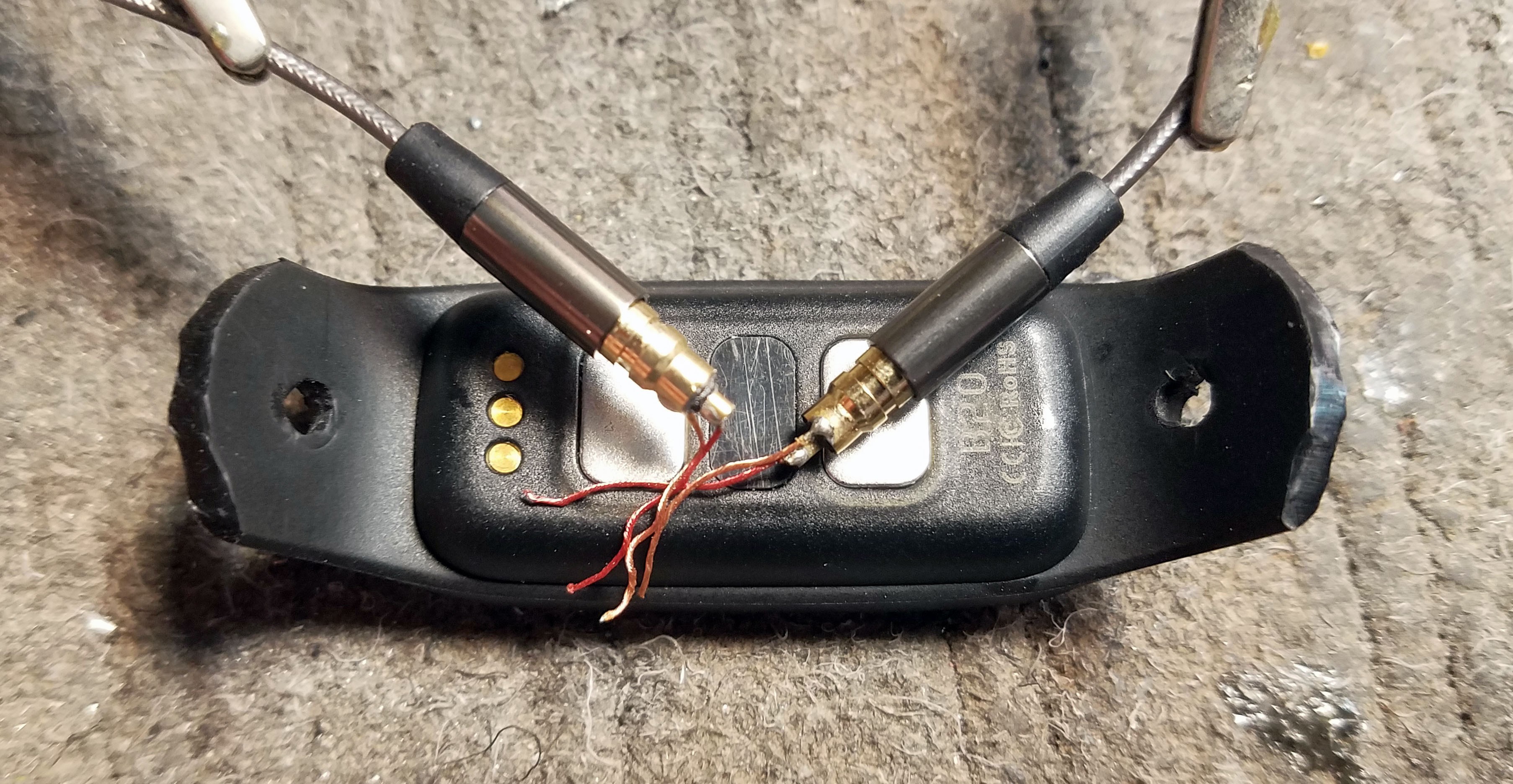
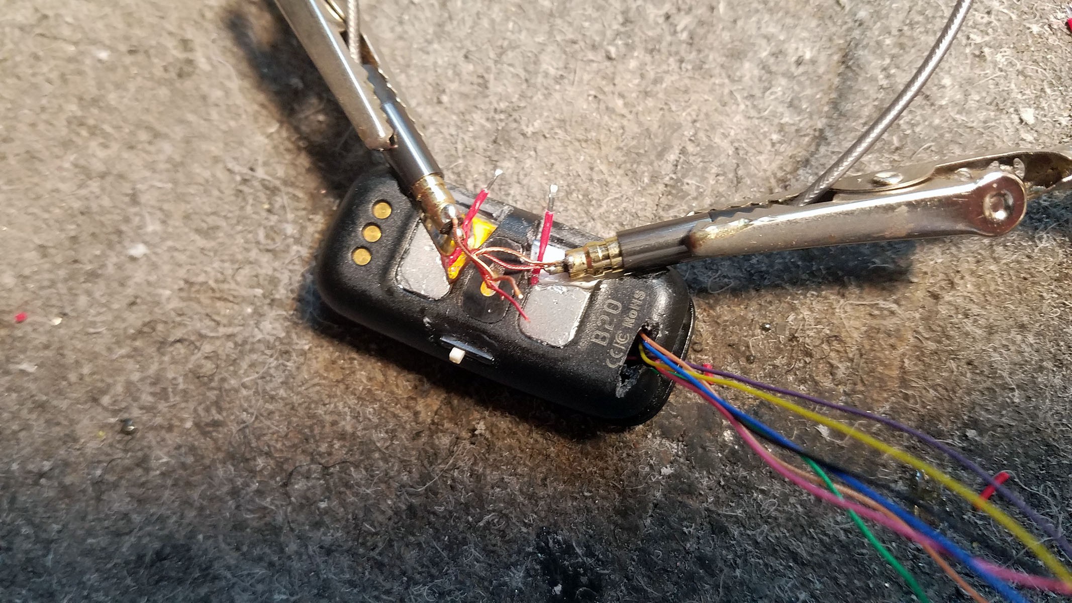
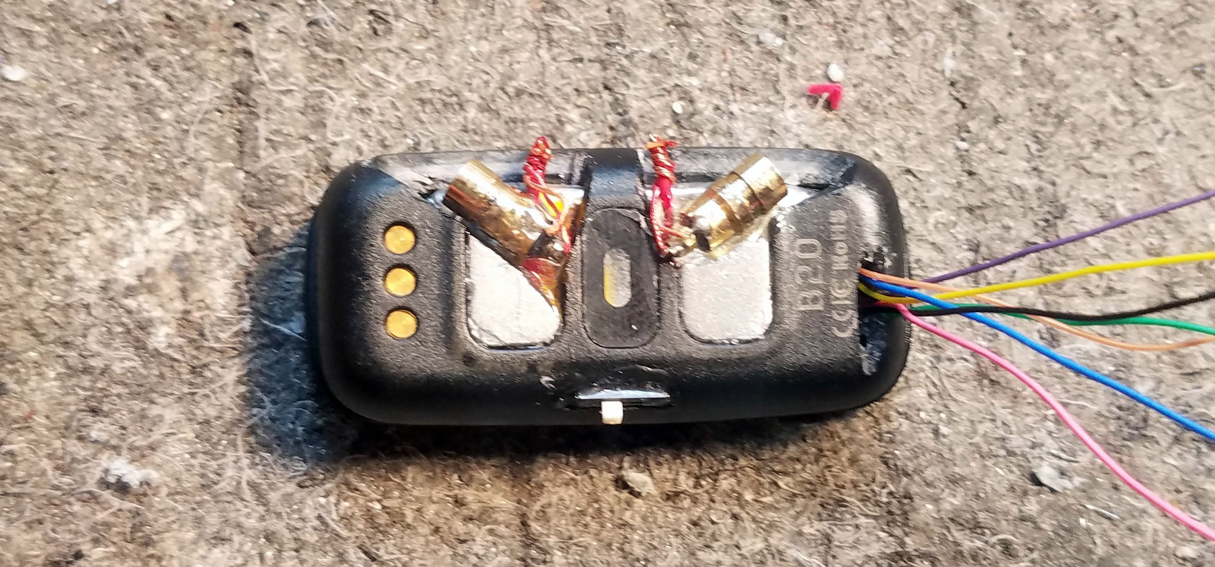
Placing the female ends of the earbud plugs by positioning the combined plugs relative to the enclosure body.
![]()
I twist the wires together making sure to get lots of contact. There should be enough space carved out of the enclosure for all this to get tucked away and covered in Bondo.
![]()
When I soldered the headphone plugs to the leads from the PCB, I was also burning off enamel. This means use lots of flux and lots of solder. I let the solder 'cook' on the wire strands for a little while just to make sure all the enamel had been brought off.
![]()
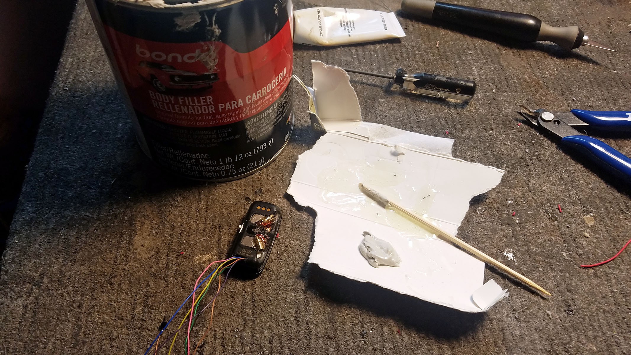
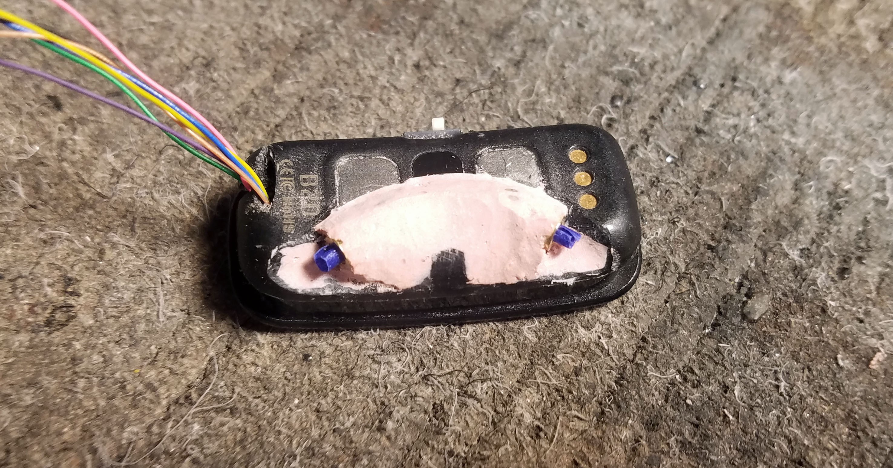
Bondo! My wife hates when I use this stuff in the apartment. I use Bondo to cover over the female electrode plugs and strengthen their placement against the plastic enclosure body.
![]()
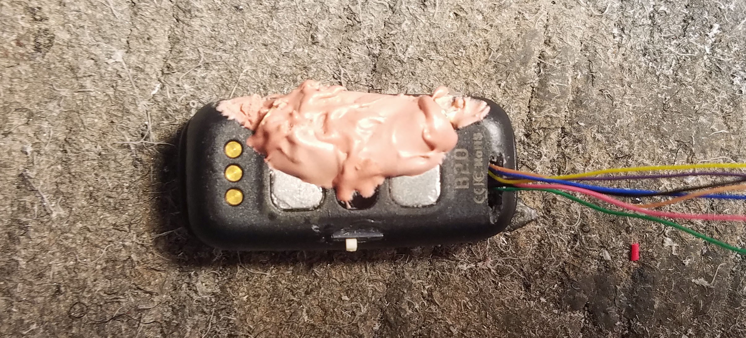
After Bondo application....
![]()
After Bondo has been shaped by a Dremel cutter, a hobby knife and some sand paper. I put rolls of masking tape inside the plugs to keep paint out.
![]()
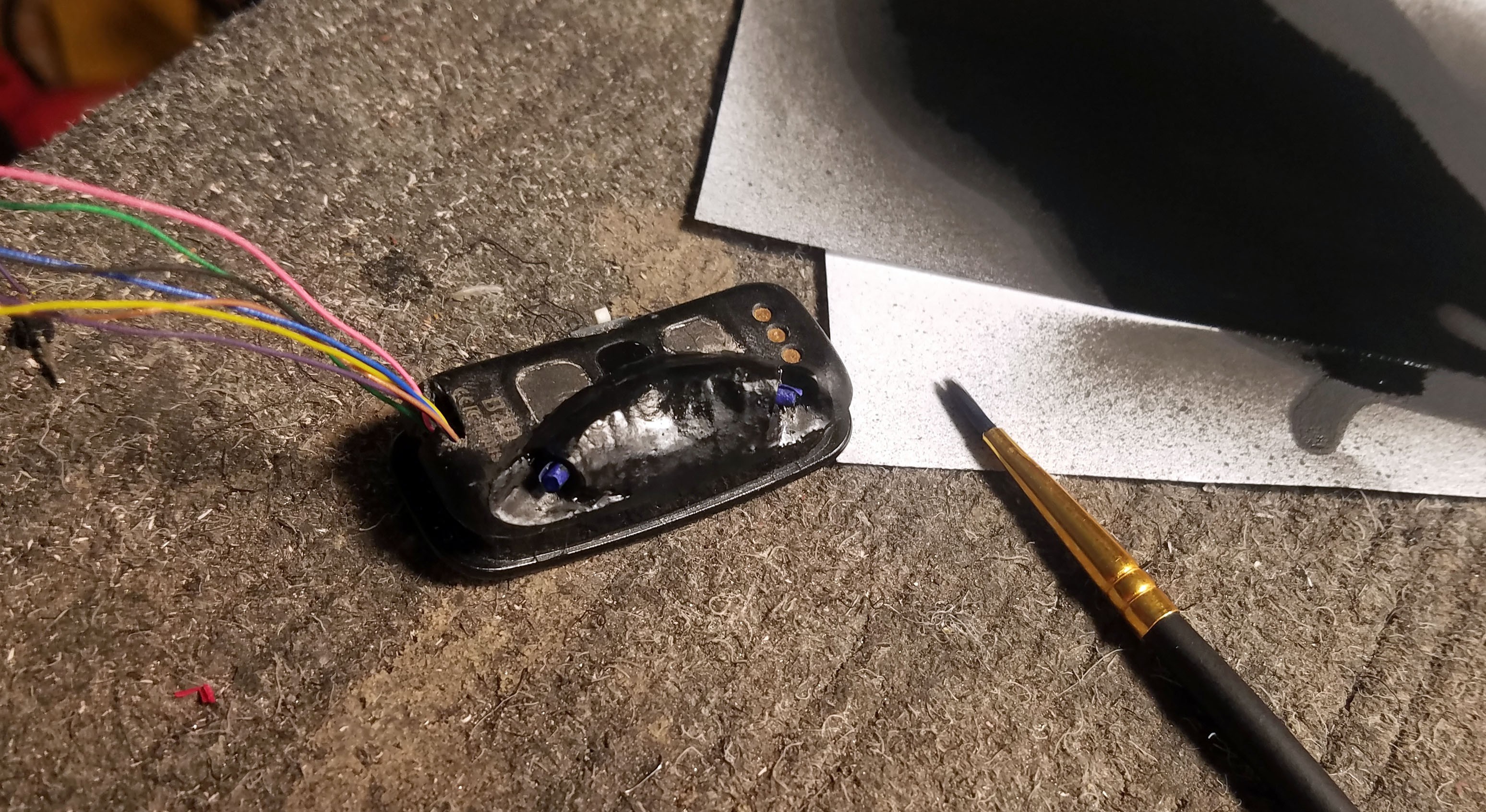
I sprayed black spray paint onto a piece of paper and then brushed it onto the Bondo.
Hacking a $35 ECG nRF52 Fitness Tracker into EEG
nRF52832 ECG fitness tracker hacked into EEG glasses using Arduino code + detect concentration/relaxation with neural network web app
 Curt White




Discussions
Become a Hackaday.io Member
Create an account to leave a comment. Already have an account? Log In.
Great work man! I'll just order this hardware today! I've done some custom PCB using the 8 channels ADS1298 but its a quite expansive IC. Want to do some experiments using this cheaper option. By the way, I was taking a look at the datasheet, and saw you have two differential channels, right?
You said it uses the RLD as your reference electrode. It means you could get up to 3 more channels, being two of them a reference and two as positive inputs, right?
Could you track the circuit of this electrodes configuration? I'm wondering to use more than a single channel, but not sure if will need to make major modifications in the hardware. If they designed on all negative inputs grounded you still could get two channels. But if they used one of the channels as reference instead of an actual RLD it would be bad for my design.
Are you sure? yes | no
No, RLD is used for reference so you won't have to worry about that. I did contemplate trying to break out the second channel on the ADS1292. My priority was to get frequency domain signal processing working on the device itself (on the nRF52 MCU). Just processing one channel required a lot of compromises, two channels would be a nonstarter as far as I can tell. If you are processing the data elsewhere (like most people) the computational overhead makes no difference and the more channels the merrier. You'll have to cut PCB traces and solder directly to the pins on the ADS1292. Tricky, but doable. Let me know if you take a crack at it, it sounds interesting.
Are you sure? yes | no
Great to know! I'm waiting for shipping right now. I'll definitely give a try and let you know. I believe I'll also try to migrate the firmware IDE to keil, my goal is to install a RTOS and use CMSIS libraries to do the filtering, I've never tried those libraries yet and seems to be pretty fast, considering they were designed by ARM itself. As soon as I have some progress let you know!
Are you sure? yes | no
Of course. Serial works the same on the nRF5x Arduino Core as it would on an actual Arduino. All the code example for this project (EEG/ECG) use serial debugging so you can use that as a guide.
ID107 (nRF51822) or ID107Plus (nRF52832)? I'll assume the first but it doesn't really make a difference. The key thing is the variant.h file. Here is a link to the ID107 variant file in the main project repo: https://github.com/curtpw/nRF5x-device-reverse-engineering/blob/master/ID107-nrf51822-activity-tracker/firmware/sandeep_arduinocore_variant/Childmind-nrf51-D3/variant.h
Look at these lines in the code:
// Serial
#define PIN_SERIAL_RX (17)
#define PIN_SERIAL_TX (18)
you need to make sure the Serial TX definition matches up with whatever GPIO on the nRF52822 you've decided to use for sending over serial.
Are you sure? yes | no
Hi Curt, great work. Do you have a an example code with Ble serial to run on ID107HR fitness tracker.
Are you sure? yes | no