-
Video Demo
09/14/2018 at 14:27 • 0 commentsMade a quick YouTube video of my progress so far. The instrument won't be able to make any "pleasant" sounds until I've got the keyboard working, but it's making some fun dirty weird sounds already:
Next step is to start making the case. My first attempt at a case was too small, so I've redesigned it and am going to start making it next week.
-
Lesson Learned / Steady Progress
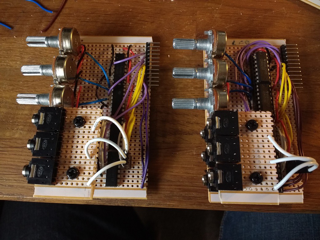
09/05/2018 at 17:18 • 0 commentsA couple of days ago I learned a lesson about not cutting corners. I hadn't been bothering to use chip holders/sockets for the numerous multiplexer chips in the synth, reasoning that they have seemed fairly immune to damage in previous projects, and that I didn't have enough chip holders to hand anyway. After spending a few hours crafting my second module, I plugged it in and started testing. It worked to an extent, but was glitchy. After lots of confused troubleshooting, I eventually surmised that one of the chips was faulty. Not being particularly great at soldering/desoldering, this ended up being a bit of a pain. Luckily in this case I was able to sort the problem out using a slightly dirty hack, but all subsequent modules now feature chip holders. Here's a spot-the-difference photo:
![]()
In other news, I'm getting quicker and better at making the modules, which all feature a pretty similar design. I have also made some progress with repurposing the toy keyboard - more details soon.
-
Taking Shape
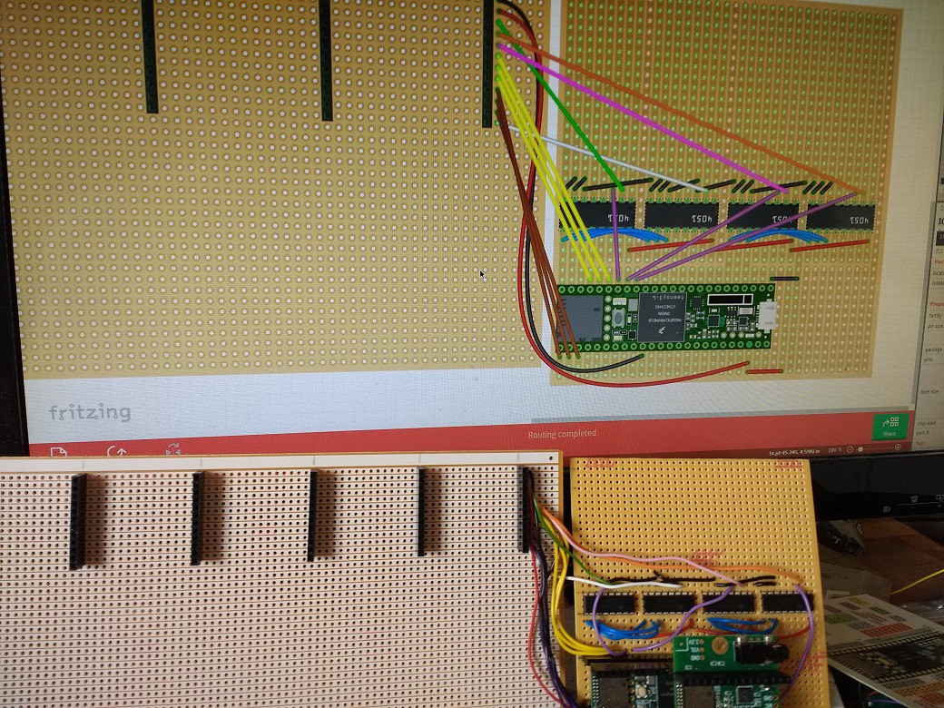
09/02/2018 at 02:50 • 0 commentsThe main circuit board is now largely built and working. It contains the Teensy and its audio add-on board, four shift registers to facilitate communication with the modules, and eight 12-pin female headers for the modules to connect to. Each module also contains four shift registers, as well as a number of sockets and potentiometers.
![]()
In total, the main circuit can handle up to 64 potentiometers (eight per module) and 64 sockets (again, eight per module). The Teensy also receives an eight-bit ID code from each module, so that it knows which module is mounted in which slot.
The wiring and soldering has been tedious but successful, with the only mistakes coming when I attempted to watch YouTube videos at the same time. It would make a lot of sense to use printed circuit boards rather than stripboard for this project in future, but the constantly evolving nature of the design means stripboard is still the most suitable method for this version. Also, I've never made a printed circuit board before, and it looks complicated...
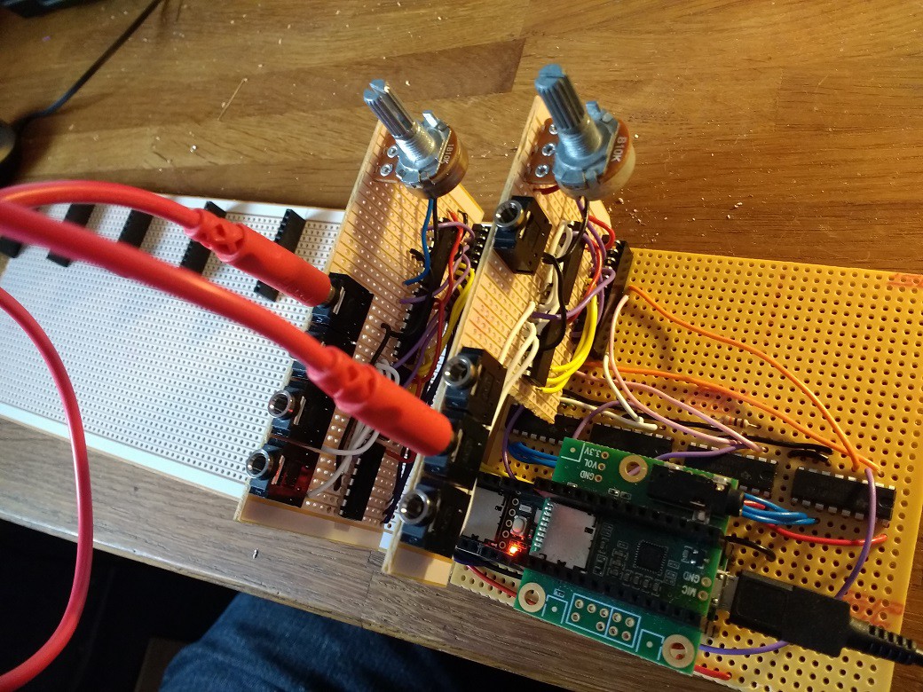
The only unforeseen issue so far was that the Teensy didn't fit underneath the modules, so I had to move it to a separate circuit board. There is a "master" module in the synth, which always needs to be present, so I moved that to sit permanently at the far end and cut away part of its circuit board so that it could fit next to the Teensy. This still left me with room for seven removable modules.
![]()
As well as the main circuit board, I've now built three modules: the "master" module (containing the main output stage and future access to things like the keyboard notes), an oscillator, and a white noise source. These are all working fine, and the focus is now on creating lots more modules as quickly as possible. Here are some of the modules I want to try to have done by the Hackaday Prize deadline:
- Master (done)
- Noise / sample and hold (done)
- Oscillator (done)
- Amplifier
- Low-frequency oscillator
- Envelope generator
- Resonant filter
- Mixer
- Bit-crusher / distortion
- Delay / reverb
- Wavetable oscillator
The synth is already producing some distractingly interesting sounds - I'll post a video soon.
-
Breadboarding
08/23/2018 at 22:00 • 0 commentsI've made a pretty decent start on the synth now. Here's a video of how it looked/sounded on the breadboard, with the jumper wires acting as modular synth patch cables, connecting three sounds in turn to the main output:
I started by constructing a breadboard circuit which detects connections between different points of the circuit in real time. In this simplified version, there are eight possible connection points, and the Teensy sketch can print a message when a connection is made or broken. Doing this directly with the pins of a Teensy or Arduino would be relatively simple, but I knew that I would need more pins than were available. I ended up using a 4051 multiplexer chip to transmit an "on" signal to each pin in turn, and another 4051 to listen for this "on" signal for each pin in turn. It means I end up with an ungainly for-loop, and it also means that the final project will use around fifty(!) of these chips, but the chips are cheap in bulk and I haven't figured out a better way yet.
After getting the simplified breadboard circuit to detect connections, I started on the code for the synthesizer audio generation. I wrote classes to represent all of the concepts in the synth: sockets, controls, patch cables, modules, etc. I hadn't done much class-based stuff in the Arduino IDE before, so I spent a while learning about how to extend classes - each module (filter, oscillator, amplifier, etc) is its own class, extended from a basic "module" class. Here's an example of me extending my "Module" class to make a low-frequency oscillator (LFO) class, using audio objects from the Teensy audio library.
#ifndef LFO_h
#define LFO_h
#include "Arduino.h"
#include "Module.h"
#include <Audio.h>

class LFO : public Module {
  public:
    LFO();
  private:
    AudioSynthWaveform _saw;
    AudioSynthWaveform _inverseSaw;
    AudioSynthWaveform _sine;
    AudioSynthWaveform _triangle;
    AudioSynthWaveform _square;
};

#endif
I tested the modules, and they sounded good, so the next step is to figure out the physical design of a robust, removable module.
-
The Genesis
08/21/2018 at 21:12 • 0 commentsSome notes on the project that preceded this one.
Earlier this year I finished a digital semi-modular synthesizer and took it to Maker Faire UK. It was unwieldy and inelegant, being a beige MDF box filled with precariously wired breadboards, connected via an Arduino Mega to a laptop which was running a hacked-together soft-synth in Chrome because that was the only way I knew to make a bunch of components talk to a customisable synthesizer.
There's an in-depth video of this project here:
Despite its impracticality, this synth did make some cool noises and successfully demonstrated the concept of using a bunch of multiplexer chips to detect connections between sockets and sending that data to a digital synth. At the end of the video, I mused that a more advanced iteration of the project might be truly modular (containing removable/swappable modules). I was also keen to somehow contain the sound generation inside the instrument itself rather than relying on a tethered laptop: ideally I just wanted a power input and an audio output.
I began investigating the practicalities of on-board sound generation. I had previously completed a big project (a retro synth-guitar hybrid) using a Teensy with an audio board/shield, and was very impressed with its synthesis capabilities, but my earlier research had led me to conclude that dynamically changing the routing between elements such as oscillators, amplifiers, filters etc was beyond the scope of the Teensy audio library. Happily, some further digging revealed this to be false: once I had got my head around pointers and references in the Arduino IDE (something I hadn't had to bother with before), it turned out to be totally possible. Suddenly, a DIY digital modular synthesizer appeared to be feasible.
I promise that the next build log will attempt to approach the present tense.
PolyMod: modular digital synthesizer
A customisable digital synthesizer. Works like an analogue modular synthesizer but cheaper, and with the ability to play many notes at once.
 Matt Bradshaw

