 Matt Bradshaw
-
1Preparation
This project involves code, electronics, and (if you want to build a case) woodwork. As well as the items listed in the bill of materials (in the "files" section of this project), here are the tools you'll need before you get started:
Software: Arduino IDE and Teensyduino for uploading code to the Teensy https://www.pjrc.com/teensy/teensyduino.html
For the electronics: soldering equipment, stripboard track cutter, wire cutters, wire strippers, crimping tool (optional - you could buy pre-crimped cables)
For building the wooden case: hand saw and/or circular saw, drill, screwdriver, hex keys
N.B. The instructions listed here should be sufficient for you to recreate my prototype synth. However, there are likely to be features that you feel are unnecessary or that you would like to implement differently, so I would recommend only using these instructions as a guide for you to create a synth that is suited to your own needs. Don't be afraid to diverge from my design decisions!
-
2Assemble the main circuit board
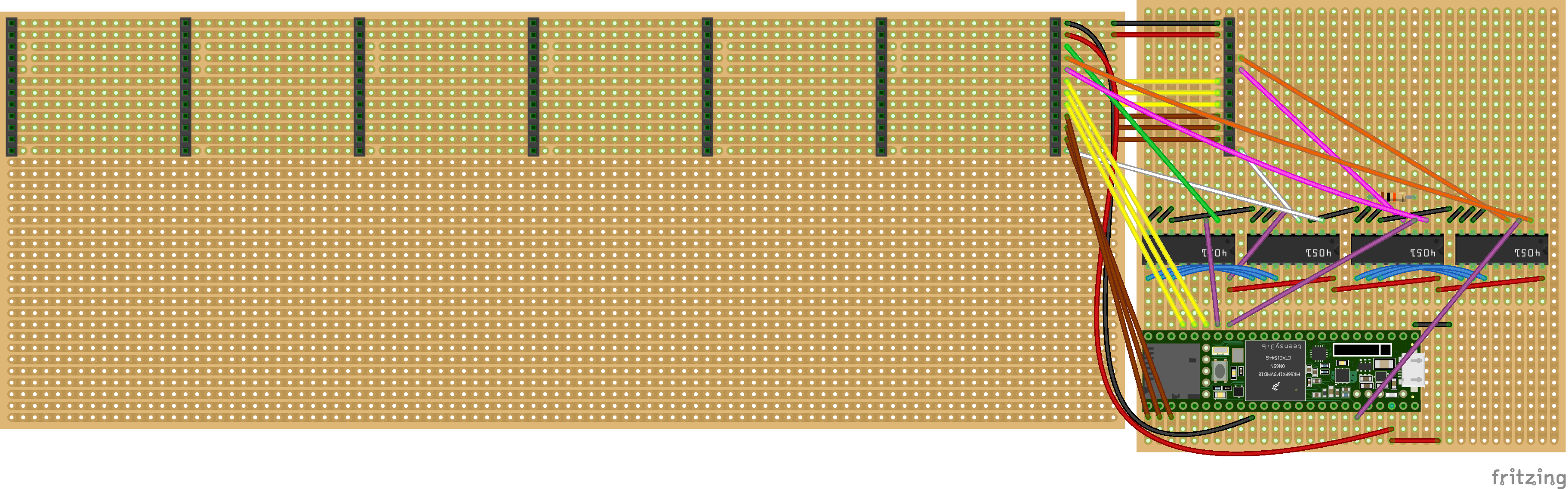
Position the components and wires according to the illustration below. Solder the components then cut the tracks. Make sure to use headers rather than soldering the Teensy directly to the stripboard, and don't add the Teensy just yet.
![]()
You'll notice that most of the module headers are not connected in the diagram - there are so many wires that it would be confusing to show on the illustration, and I'm not very good at schematics! Basically there are four wires for each module socket that need to be wired to the appropriate channel on each of the 4051 chips. You can see in the illustration that socket 7 has been fully wired up already. To wire up socket 6:
- Pin 3: wire this to channel 6 of the first 4051 chip
- Pin 4: wire this to channel 6 of the fourth 4051 chip
- Pin 5: wire this to channel 6 of the third 4051 chip
- Pin 12: wire this to channel 6 of the second 4051 chip
You'll need to refer to a diagram of the 4051 chip to see which channel is on which pin. Once you've wired up channel 6, wire up the other sockets in the same way (i.e. the wires from socket 5 go to channel 5 of the various 4051 chips).
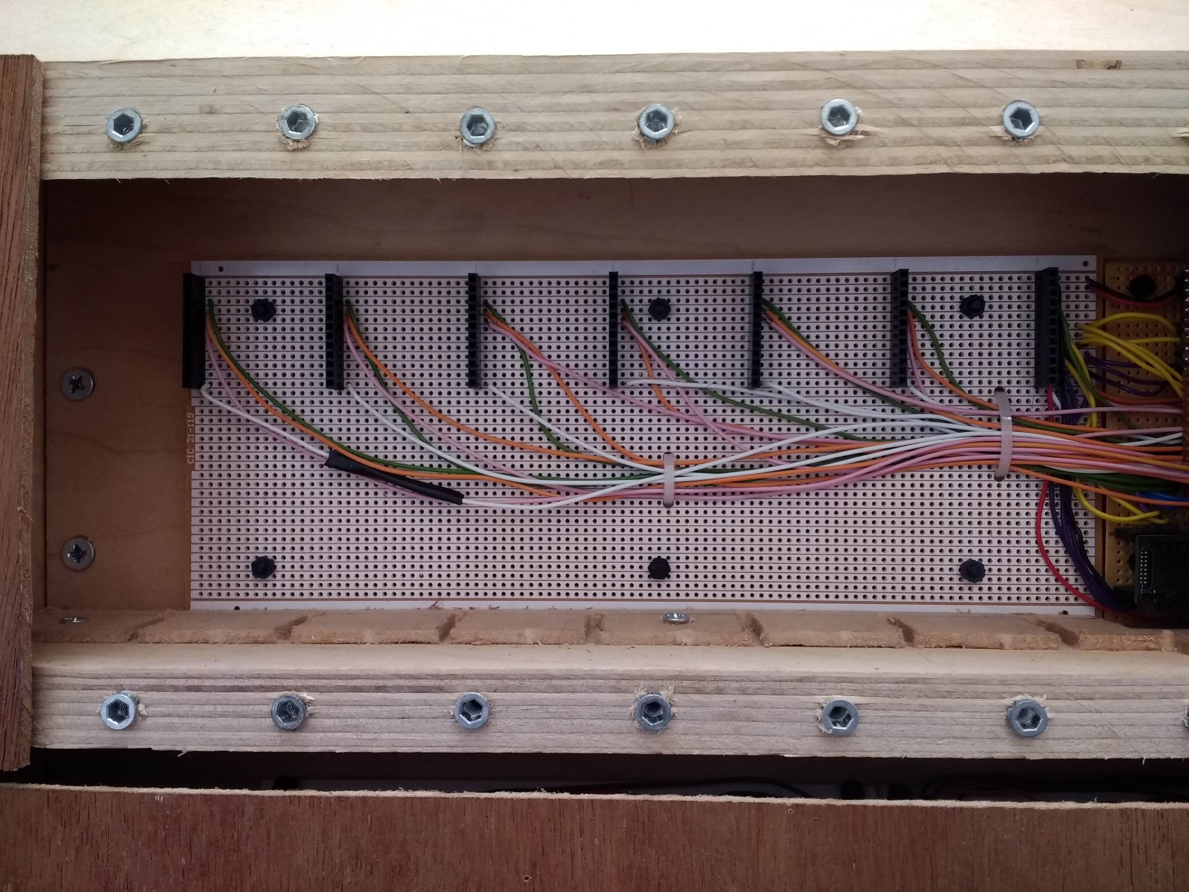
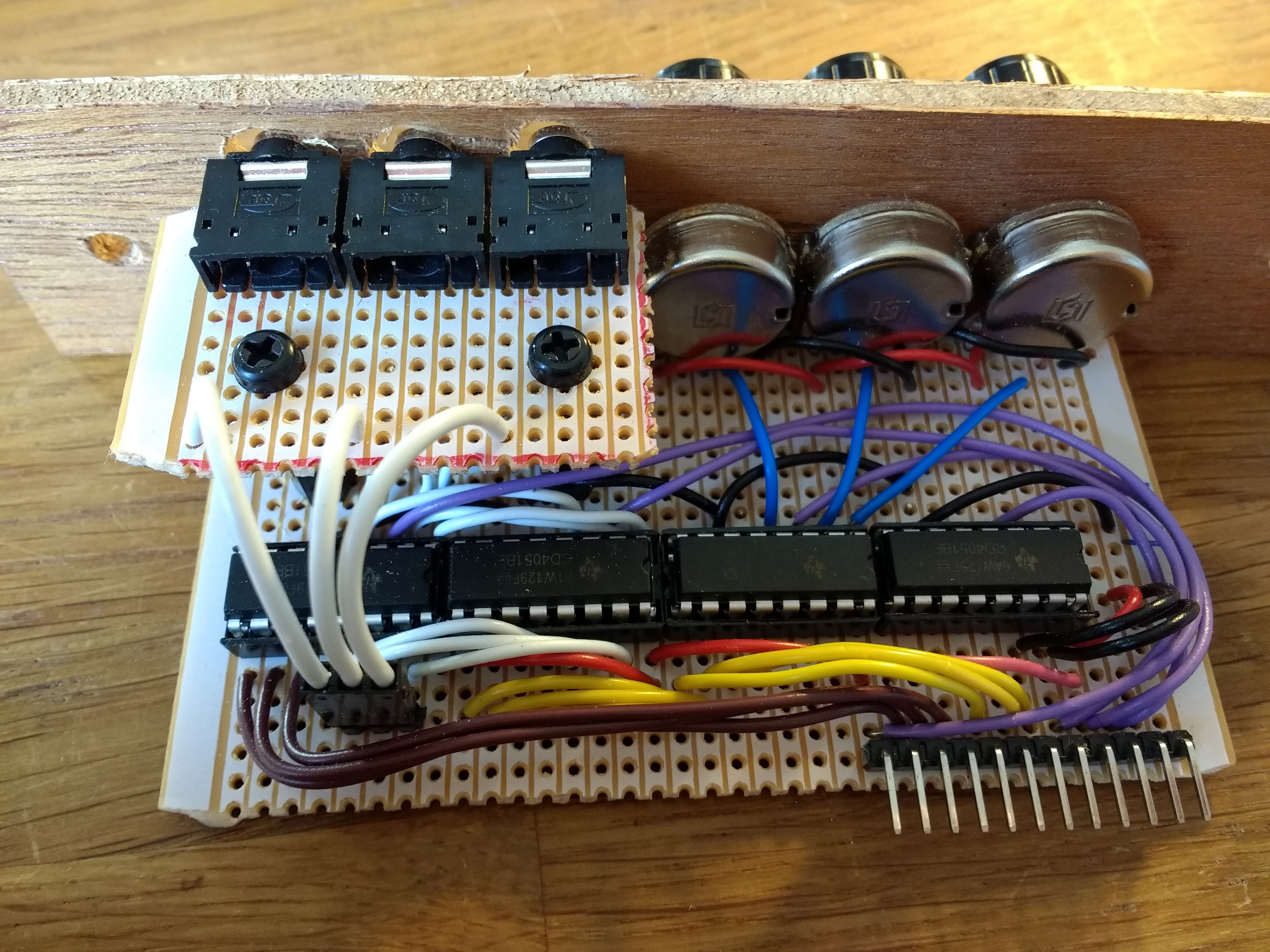
Here's a photo of how the module sockets are supposed to look, in case that helps!
![]()
-
3Add the Teensy
Solder stackable (extra long) headers to the Teensy, such that it is has male pins protruding below and female headers on top. Solder male headers to the Teensy audio board, such that its pins protrude below, and push the audio board's pins into the Teensy's female headers, making sure the pin numbers are aligned.
Test the Teensy before connecting it to the main circuit board by uploading some test sketches from the Arduino IDE. Try "Basics/Blink" to test the Teensy itself and "Audio/Synthesis/PlaySynthMusic" to test the audio board (music should play through the headphone socket).
Next, carefully push the Teensy into the appropriate female headers on the main circuit board and check it still works. If it cuts out or you can't upload sketches any more, disconnect the cable and check your soldering.
If everything is good, you can upload the PolyMod sketch, which can be found on the PolyMod GitHub repo: https://github.com/mattybrad/polymod
-
4Assemble the master module
There are seven slots into which any modules can be inserted, but the final slot is reserved for a master module, which is not designed to be removed. It makes sense to assemble this module first, as the other modules are useless without it.
I had to snap some pieces of stripboard in half to achieve the exact size I wanted for the modules, including the master one - you may be able to find the right size of stripboard or adapt my design but, if not, stripboard can be snapped fairly easily along a line of holes. The size of the stripboard is very important because it will affect how far the front of the module protrudes from the circuit board - if the modules protrude by different amounts, it will be difficult to mount them neatly in the case later. A few millimetres of difference is acceptable, but make sure to count the holes carefully before snapping the boards.
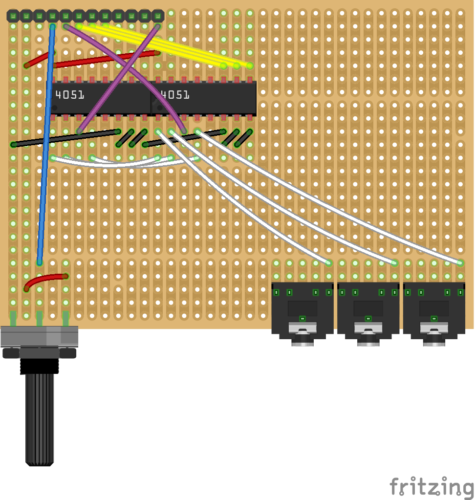
Once you have a piece of stripboard the correct size, assemble it according to the illustration below. Note that there are only two 4051 chips. This is because the master module doesn't need to identify itself (since it always sits in the same slot), and because there is only one knob (for volume), therefore no need to multiplex the analog signal. Basically, you could happily use the normal module layout for the master module - it just happened that I didn't leave myself enough space in my build to fit a whole module in where the master module was supposed to go (the Teensy was in the way), so I ended up cutting a chunk out of the stripboard, necessitating the loss of two 4051 chips.
![]()
-
5Assemble the oscillator module
Now that you have the master module, you need another module which can connect to it. The most obvious choice is an oscillator module, because it will produce a waveform which you will be able to hear, allowing you to test that everything is working so far.
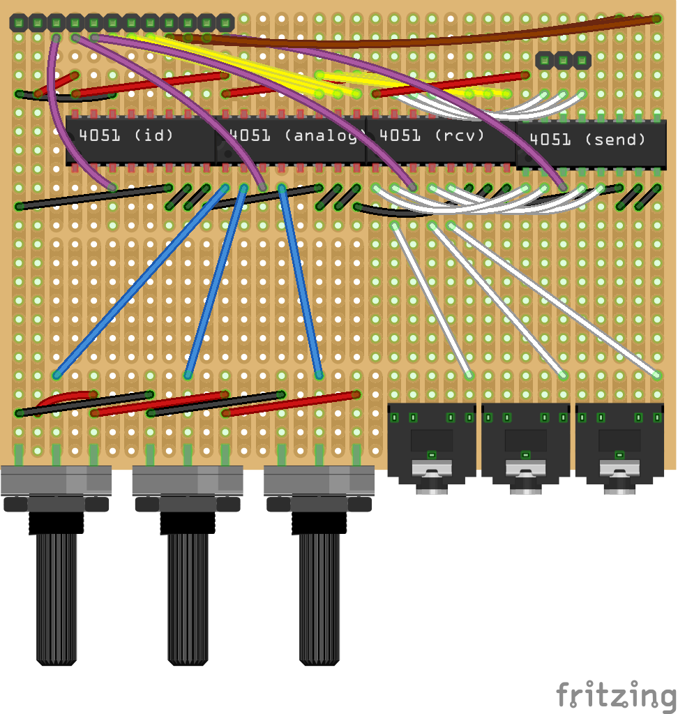
Assemble the oscillator module according to the illustration below. Note that the header on the top left should actually be a 90 degree header, with the pins protruding off the board.
![]()
In order to fit more sockets into a relatively small space, some of the modules (including this one) require a small extra piece of stripboard, containing extra sockets, to be mounted with PCB standoffs, as shown in the photo below.
![]()
If you wanted to keep things simpler, you could increase the height of each module and have all the sockets soldered in a row, something that I might consider doing in the future!
-
6Test the first two modules
Plug the master module into the rightmost of the eight identical female headers, and the oscillator module into the header next to it. Power up the Teensy, connect a pair of headphones to the audio board, and use a 3.5mm patch cable to connect the bottom left socket of the oscillator to the top socket of the master module. If everything is working, this should generate an audible tone, with the frequency (pitch) controlled by the potentiometers.
If not, check your soldering.
At this stage, you should also test the oscillator module in each of the other slots, to make sure the headers are all connected correctly.
-
7Assemble more modules
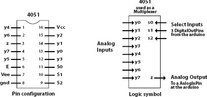
At this stage, you basically have a working (albeit rather limited) modular synthesizer. The next thing to do is to add more modules. The modules make extensive use of 4051 multiplexer/demultiplexer chips, and it is helpful to know this chip's pin layout (image credit https://playground.arduino.cc/Learning/4051):
![]()
You should check the source code to see exactly which sockets and potentiometers are connected to which 4051 pins, and also to see what the ID number of each module is - the ID number is set by grounding certain pins of the first multiplexer. Each grounded pin is treated as a binary "one", while all other pins are treated as "zero". For instance, grounding pins 1 and 2 would generate the eight-bit binary number (byte) 00000110, which is the decimal number 6, defined in the code as the ID number for the "filter" module.
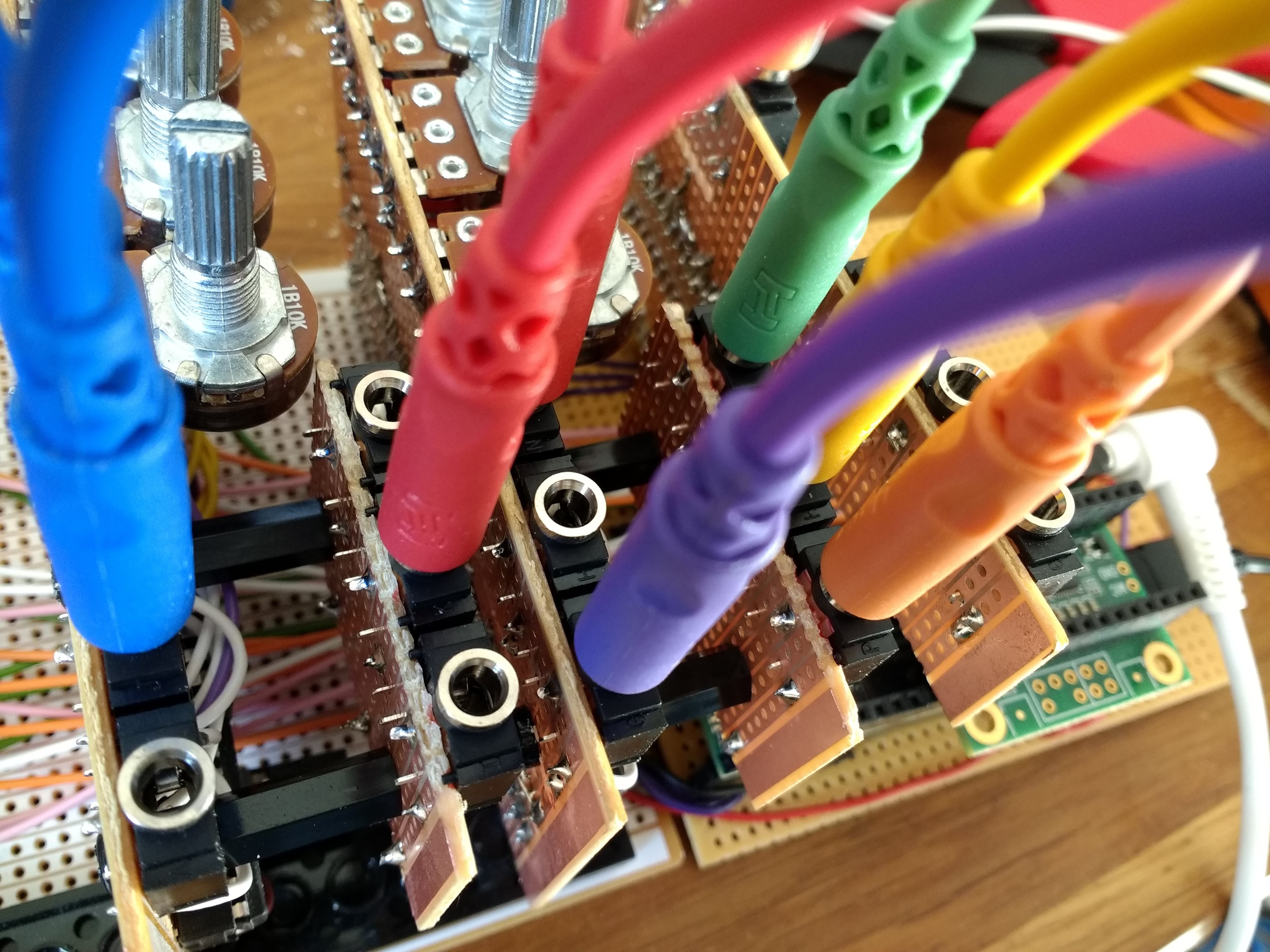
Make sure to test each module after you assemble it. At this stage, your synth might look a bit like this:
![]()
-
8Make your own custom modules (optional)
I have written the code for quite a few basic modules, but one of the joys of modular synthesis is the sheer variety of modules available, so I encourage you to design and assemble your own modules. To do this, first work out how many sockets and potentiometers you'll need, and build the module in the same was as before. You can also use other user inputs, such as toggle switches, momentary buttons, or even light sensors - anything that can be read by the Teensy's analog input pins.
Next, choose an unused ID number and define it at the top of the sketch with the other module ID numbers. Ground the appropriate pins on the module ID chip.
Now create two files in the project's directory called (for instance) MyModule.h and MyModule.cpp. Include the MyModule.h file alongside the other module header files at the top of the sketch and, using the other modules' code for reference, try creating your own module.
A great starting point is to look at the Teensy audio online GUI, which has documentation for the Teensy audio library's built-in audio objects. https://www.pjrc.com/teensy/gui/index.html
Try experimenting and see what you come up with! Some ideas to get you started: how about a wavetable oscillator, or a drum sample player? Or maybe, if you're feeling ambitious, a 16-step sequencer? Be creative!
-
9Build keyboard section (optional)
I decided to add a keyboard to my synth because I wanted it to be a standalone instrument. I also decided to build the keyboard mechanism myself, which is a decision I now slightly regret!
I reused the plastic keys from a toy keyboard because I had no easy way to make piano keys myself. However, rather than trying to use the toy's existing electronics, I thought it would be neater to make my own circuit board, using tactile buttons to detect key presses, and multiplexers to serialise the data.
While I do like having a keyboard as part of the instrument, I wouldn't recommend implementing it in the way I did. The action of the keys (which are also too small!) is unlike a regular keyboard, and it was quite fiddly and repetitive to wire up the switches and mount the keys. It's possible that you could get better results with bigger keys (maybe 3D printed?) and a different type of button, but overall I would recommend that you either add a MIDI input to the project or perhaps use an existing keyboard in a better way than I did!
-
10Build wooden case
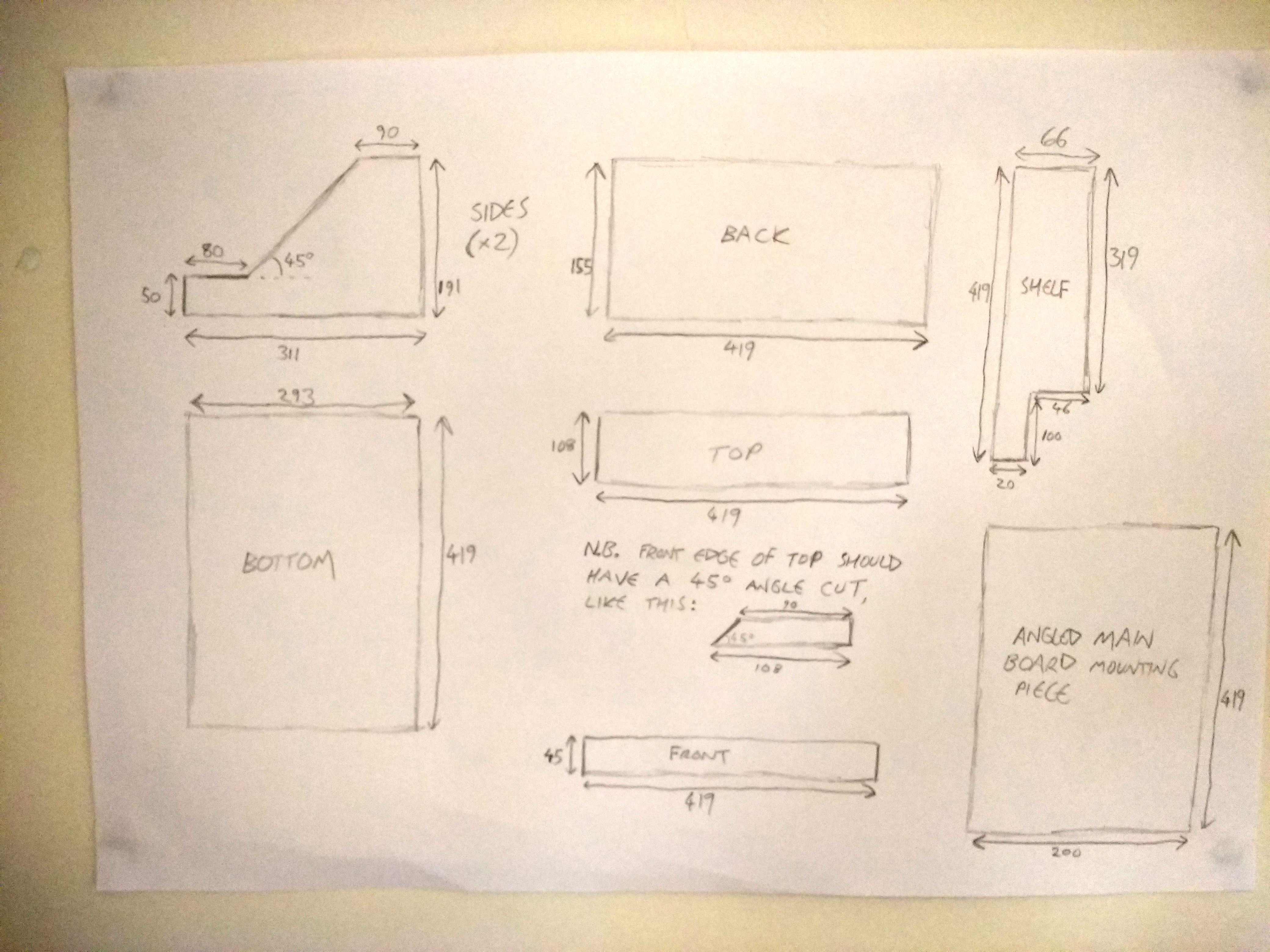
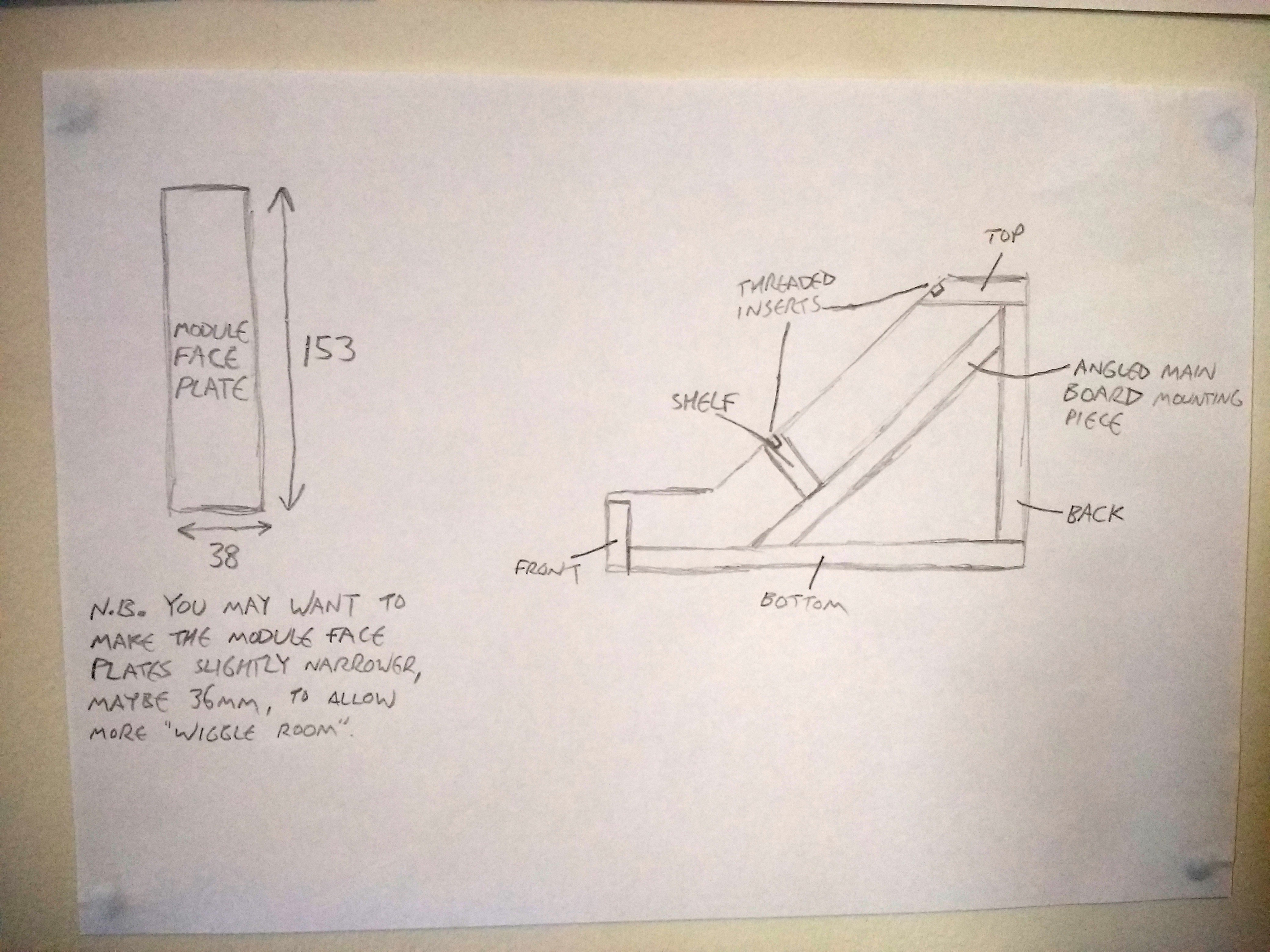
At this stage, your synth should be working but is probably rather fragile! I made a case for mine out of 18mm plywood, which I obtained for free from a bookcase that was being thrown out on my street. You may well want to make an entirely different type of case for your synth, but in case you want a starting point, here are the measurements for my design:
![]()
![]()
Almost all the wooden parts are made from 18mm plywood and screwed together using wood screws. You could also glue your case together, but I like being able to take it apart again easily!
The module face plates are not made of 18mm ply, but instead from 3mm ply. I happened to have a sheet of this from an old wardrobe, but I found it quite fragile and difficult to work with, so I would recommend choosing your module face plate material carefully. Aluminium would probably be a good option, which I may use in future.
I also used the thinner wood to cover the area around the keyboard, but I have not given measurements for this since your keyboard (if you use one) will almost certainly be a different size.
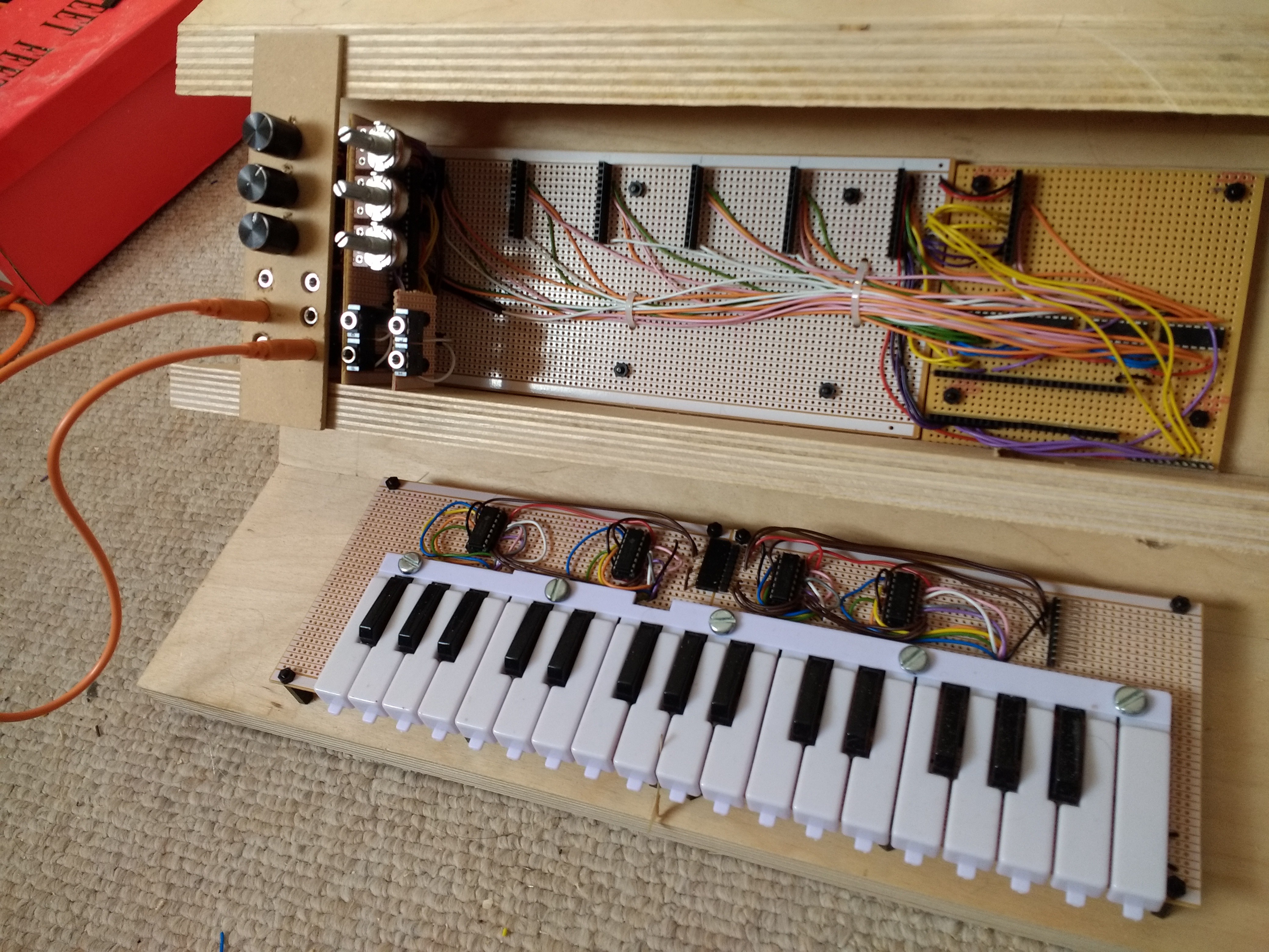
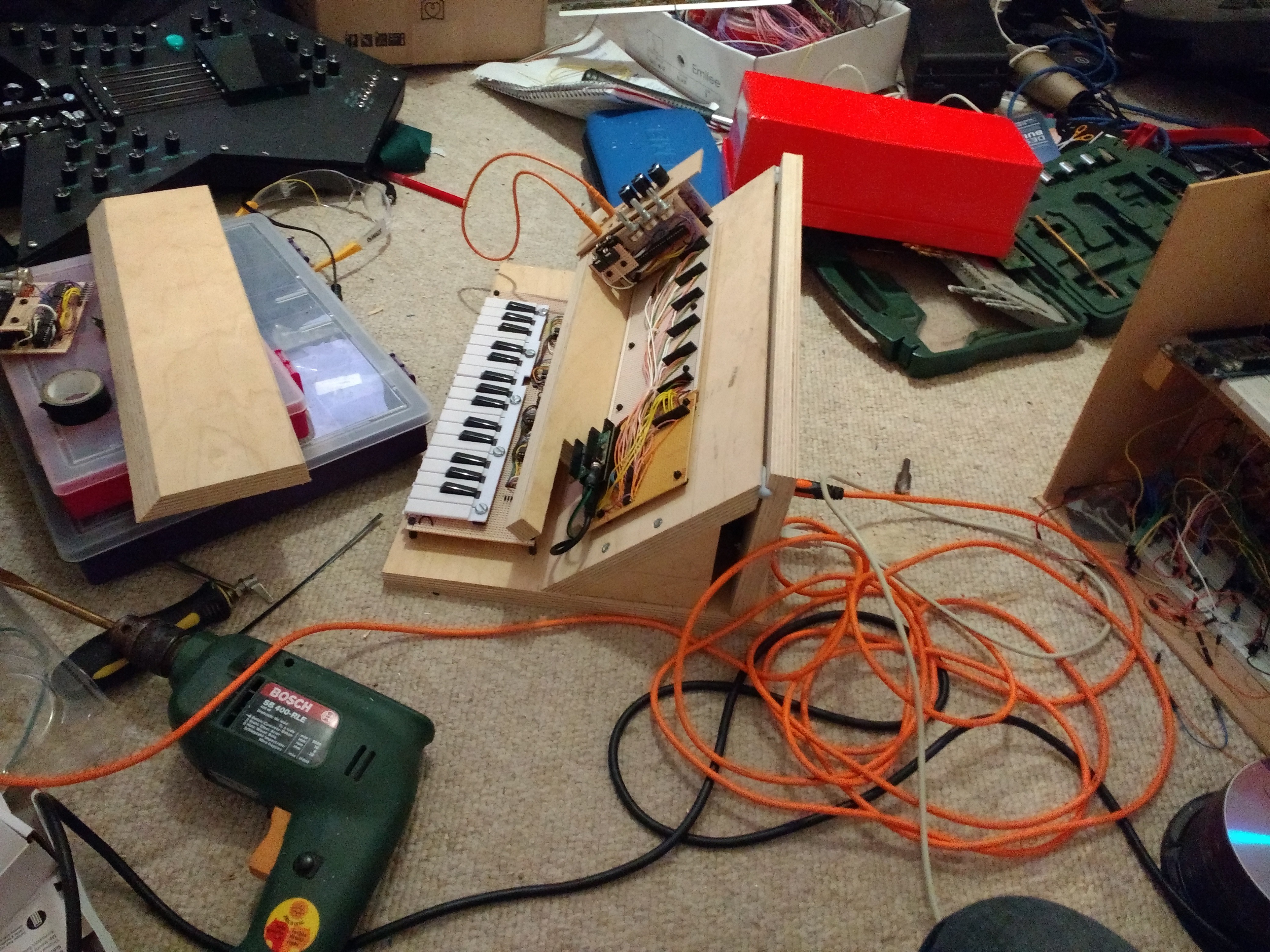
Here are a couple of photos of how my synth looked during construction, in case that's helpful:
![]()
![]()
PolyMod: modular digital synthesizer
A customisable digital synthesizer. Works like an analogue modular synthesizer but cheaper, and with the ability to play many notes at once.
Discussions
Become a Hackaday.io Member
Create an account to leave a comment. Already have an account? Log In.