MakersBox
-
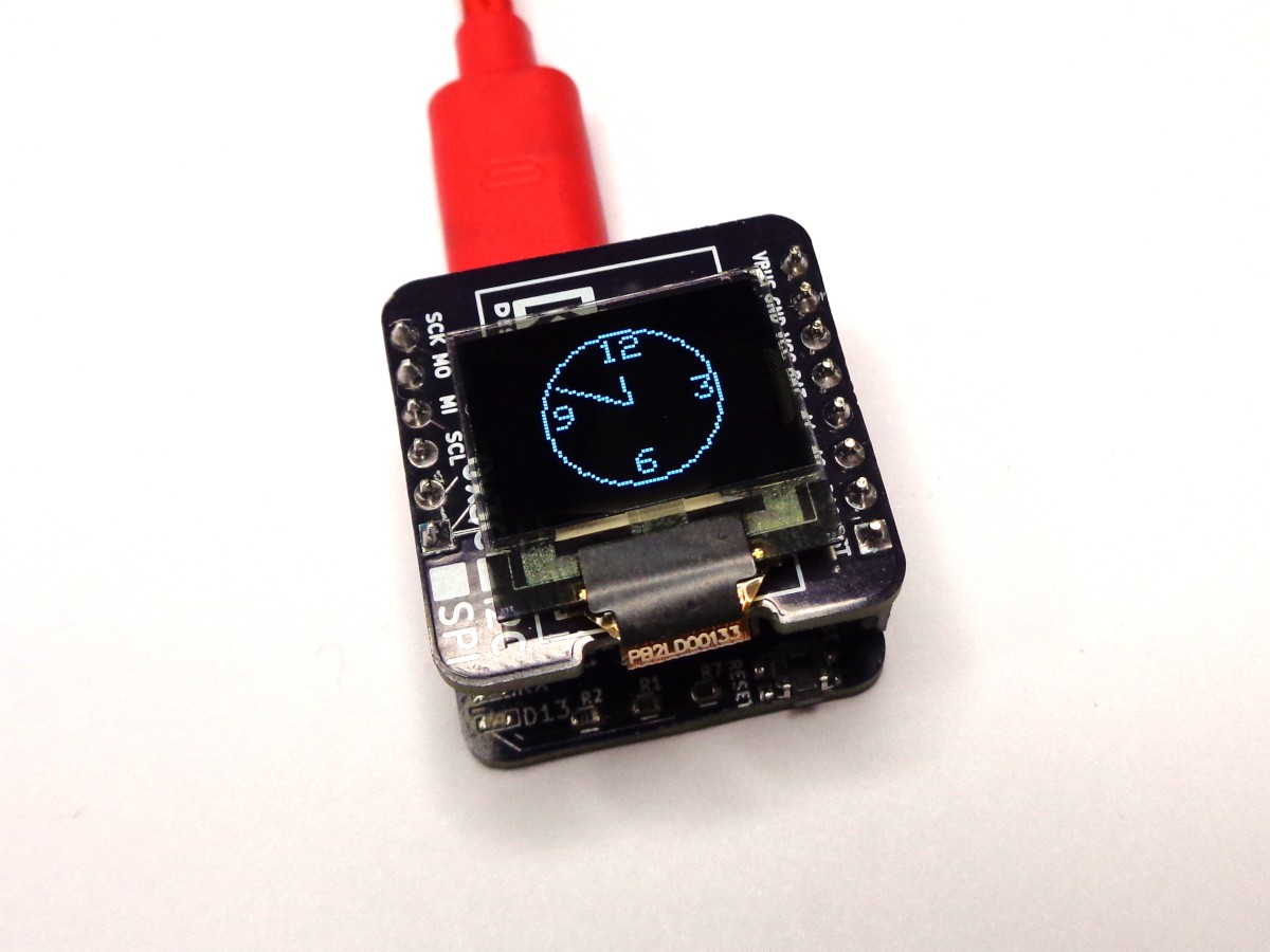
OLED Display
09/12/2018 at 01:25 • 0 commentsI wanted a small display. Adafruit has a 128x32. SparkFun has a 64x48. They both use SSD1306 driver chips.
![]()
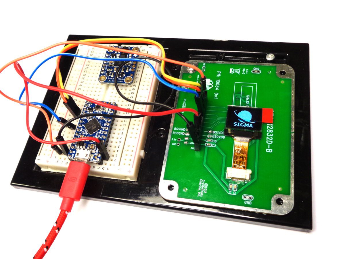
I found a company called Crystalfonzs that sells SSD1306 displays and even a dev board, very inexpensively.
![]()
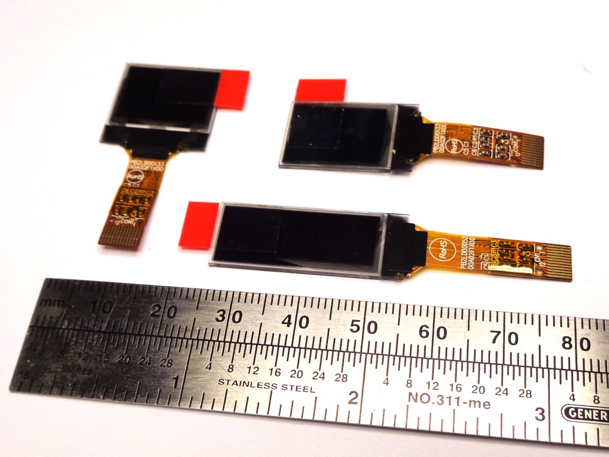
I bought a number of display modules with ribbon cable connectors . This seems like a good route because while the connector adds expense, it allows the display to be changed and eliminates a nasty bit of hand soldering.
![]()
All the displays work. The libraries written by Adafruit and Sparkfun work well for the display size they sell, but modifying the code, or even rotating the screen is a bit beyond my coding level at this point.
-
Data Logging
09/09/2018 at 01:22 • 0 comments![]()
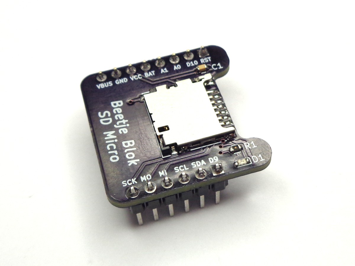
My only experience with SD cards and Arduino was with Adafruit's Wave Shield, so I knew you could at least read data. An SD card seems like an ideal way to data log because you can remove the card and read it on a computer and not worry about having to transfer data via serial. For long term data logging, I'm interested in power consumption. For short term data logging (like model rockets), I'm interested in how fast I can write data.
For the circuit, I copied Adafruit's Micro SD breakout, minus her five volt level shifting. There is a SD library in the standard Arduino libraries.
My first attempt using a 4 Gb card resulted in failure, and I'm not sure why. I formatted the card using the official formatter recommend in Adafruit's tutorial. The card was recognized by the Arduino, but wouldn't read or write and subsequent attempts to reformat were unsuccessful.
I did a bit of a design review before throwing another card at it. Nothing showed up, and my next attempt with a 2 Gb card was successful. Was it Einstein who said "Insanity is doing the same thing twice while expecting different results"? Welcome to crazy.
I wrote some test code to see how fast it was writing. I can basically three data points 43 times a second, or once every 23 ms. Not terribly fast, but fast enough? We will have to wait for the EEPROM blok to do a comparison.
-
Under Pressure
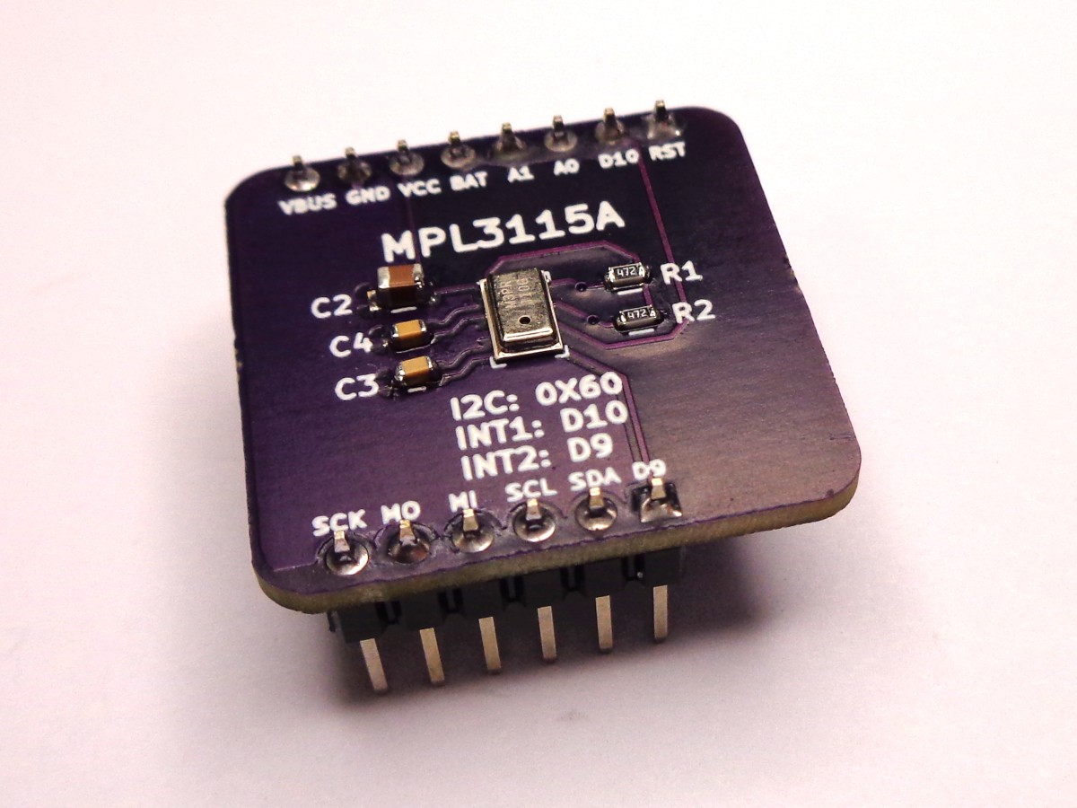
09/07/2018 at 16:39 • 0 commentsThis whole project actually started by wanting to measure the vacuum inside a bottle without any bulkhead penetrations. It needed to fit through an opening smaller than most dev and breakout boards, so I was looking to combine a Atmega328 and a sensor on a narrow PCB. Creating square circuit boards is just a diversion for now.
![]()
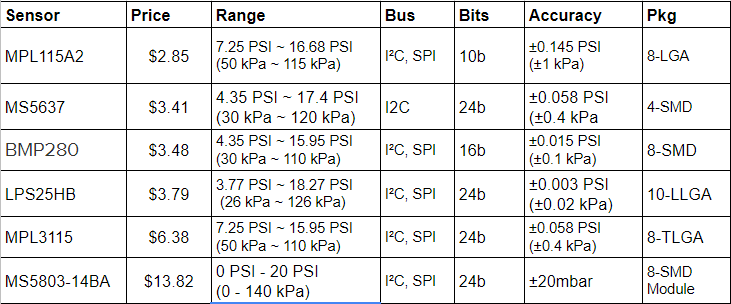
There are a number of pressure sensors with good Arduino libraries. To date, I've worked with the MPL3115A and the MS5803, which are at the high end of price and capability. Here is a little survey I did.
The MS5637 or LPS25HB look like better choices for price and performance. I also need to investigate the difference in speed between I2C and SPI. For rocket telemetry, we want to focus very intently on a very brief duration event and that might be a factor. I'm sure that will play in to the EEPROM verses SD card choice as well.
-
LiPo Battery Power
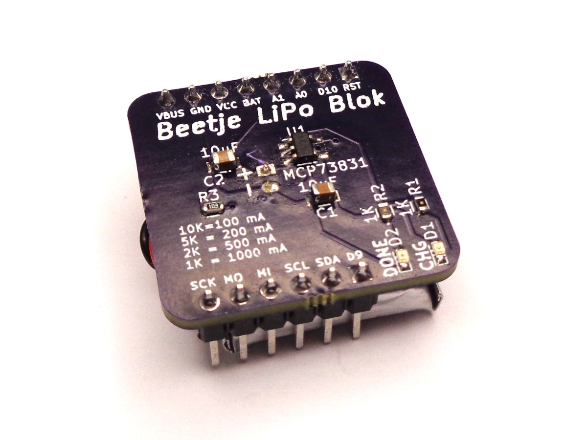
09/07/2018 at 01:00 • 0 comments![]()
I love coin cells, but I'm not sure they will cut it if we need to do something more current intensive (like write to SD cards). I shopped around and found a small square LiPo battery that will fit the footprint. With only 150 mAh, it is not going to do a whole lot for a whole while, but it is a start.
The charging circuit I borrowed from Adafruit's Trinket Backpack. I put connectors on it for both JST PH and SH, the former seeming to be the most popular for LiPo batteries, the latter being what the battery I selected came with. The unpopulated PH header can also act as test points or solder connections.
I released my first bit of magic smoke on this project by hooking the battery in without checking the leads match the markings on the board. The back current immediately fried the MCP73831 and burnt my finger, all in the process of about two seconds. Hum, maybe a protection diode or PTC? I've learned that lesson the hard way more than once.
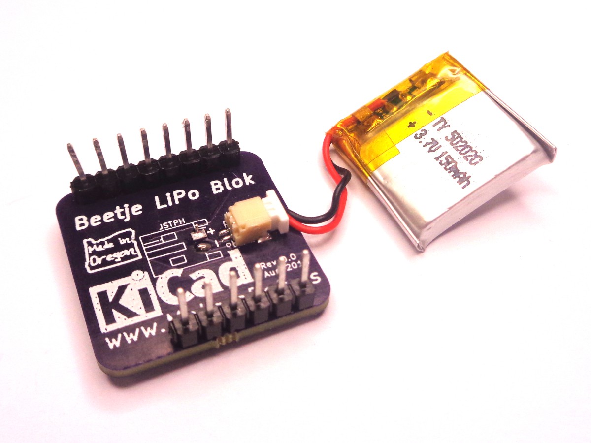
![]()
I am having an issue with the red charge light being dimly lit after disconnecting the USB power. I believe the battery diode D4 on the 32U4 board is leaking stray current back into the circuit. More on that latter. I'm also wondering why the heck I didn't think to put a power switch on this board (or the 32U4 for that matter). The headers and location are also not sorted yet. I'm either going to use through-header so it will go on top of the 32U4 board, or piggy-back the 32U4 on top of it in a more permanent arrangement.
-
Battery: Swing and a Miss
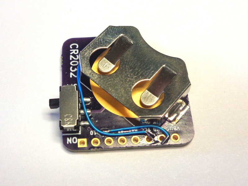
08/28/2018 at 20:33 • 0 commentsThe battery and accelerometer boards came in at the same time. The accelerometer worked, the battery, not so much.
![]()
The first problem is that fitting a 20mm coin cell into a square inch with headers on each side is a loosing battle. My idea was to drop the front six pins to allow entry and to angle the holder so the battery would not short out on the back header.
![]()
The main board requires insulation such as electrical tape to keep from shorting the bottom of the front bus pins on the battery holder. Minor issue. I also somehow managed to get the battery backward in the schematic, requiring some trace cutting and bodge wire. The good news is that per the whole KISS principle, I'm only out $5 in PCB and an hour of screwing around trying to figure out why ground and VCC were shorted even after I cut the traces (its the vias, dumbass).
Next up? RTC or pressure.
-
Acceleration. First Blok. First Success.
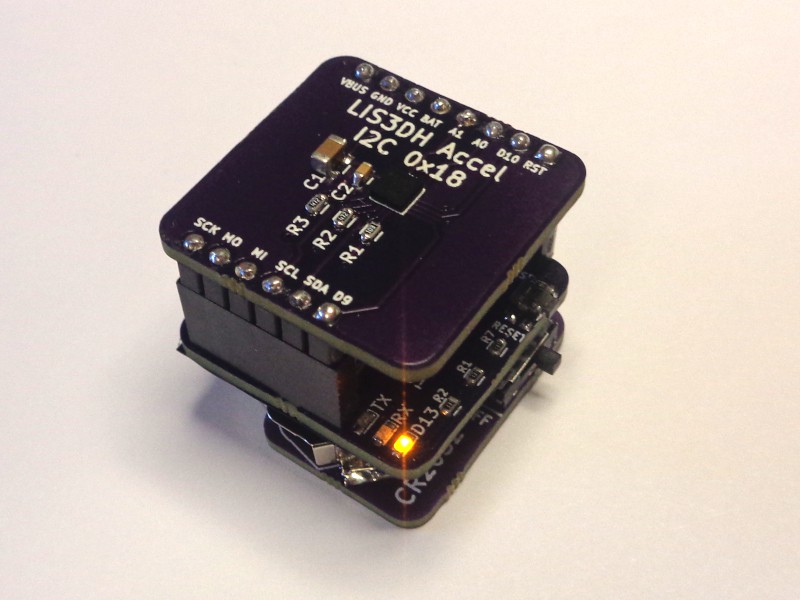
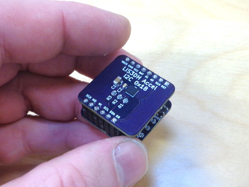
08/28/2018 at 20:18 • 0 commentsIn an earlier attempt at an integrated breakout board, two of the four I2C subsystems failed to work. The accelerometer was one of them, so I figured it would be a good acid test. If you go to SparkFun or Adafruit, you will so a whole plethera of breakoutboards, so it is a bit hard to choose. I decided on the LIS3DH because it was I2C, read up to 16g, and was fairly inexpensive. Another thing you will quickly recognize is that all of them are some form of BGA package, making hand assembly difficult (and ultimately why I failed earlier).
For hand soldering BGA, you pretty much have two choices: hot air or reflow. Either way, you life will be easier if you have a stencil. I get mine from OSH Stencil. I was already getting a stencil for another board, and just threw the footprint on. The other resistors and capacitors were hand soldered.
![]()
One of the advantages of using something SparkFun or Adafruit has done, is using their libraries. For the LIS3DH, there are actually two:
https://learn.adafruit.com/adafruit-lis3dh-triple-axis-accelerometer-breakout/arduino
As for headers, as you will see with the battery problems, I'm still trying to figure it out. For now, I'm going with female on the main board (like Arduino) and male on the Bloks. I'm going to try and source some shorter headers.
-
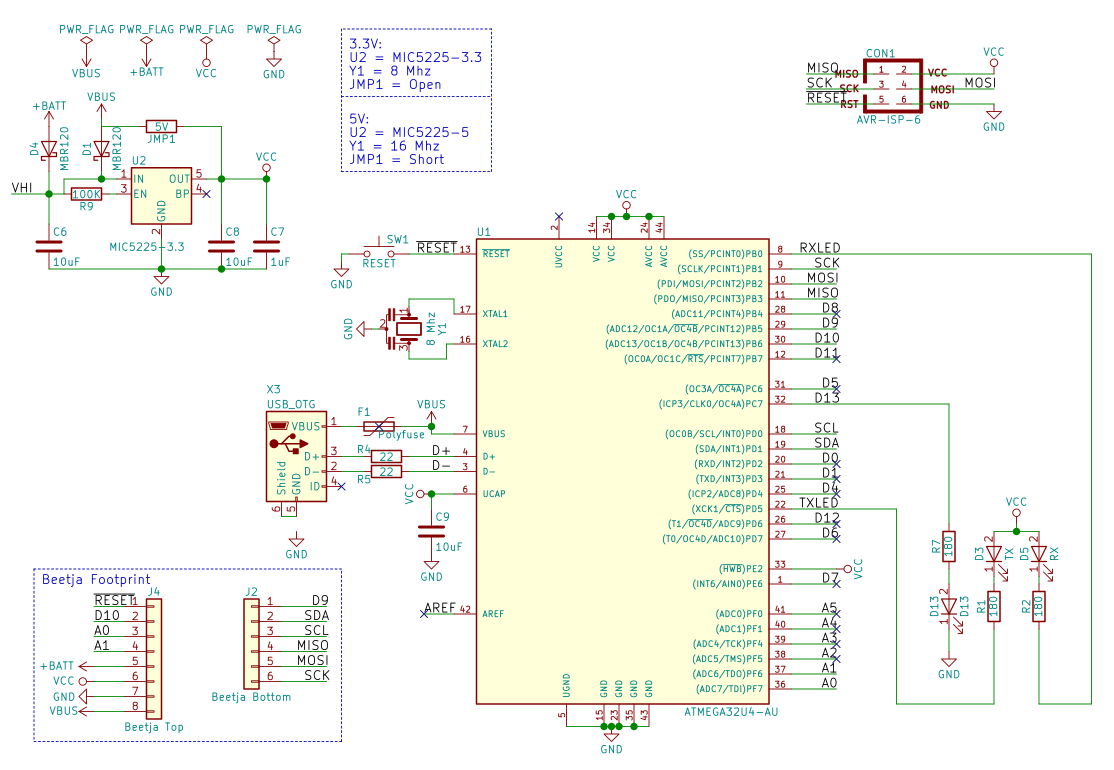
Beetje 32U4 Blok
08/22/2018 at 01:52 • 0 comments![]()
So again, for those commenters who didn’t read this far, I don’t think a 32U4 dev board is my gift to mankind. In fact, even copying Adafruit’s IstyBitsy straight into KiCAD is going to be at the limits of my ability. I like the IstyBitsy’s power management and reset button and the Pro Micro’s LEDs and polyfuse so I am going to fuse those together (pun intended).
![]()
The physical layout is actually pretty easy since I’ve got a defined board space and pin spacing. I want to make it so the bloks cannot be put in backward, so I’ll put eight pins on top row, six on the bottom row (wow, echos of Arduino here?). This will also allow us to use standard Arduino through headers if we start start stacking. We need:
- Power: VBus (USB 5V), VCC (3.3V), Vbat, Gnd
- I2C: SDA, SCL
- SPI: MOSI, MISO, SCK
- Digital I/O: D9, D10 (both PWM)
- Analog I/O: A0, A1
With a RST pin, that makes 14. That, like the size, feels just right for keeping us focused on keeping it simple. If we need anything more I/O intensive like an LED matrix, it will have to be driven by SPI or I2C. I’ve tried to follow the schematic flow for the physical layout, with power on the left and outputs on the right, although I’m sure that convention will break down quickly in places.
![]()
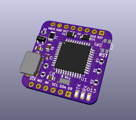
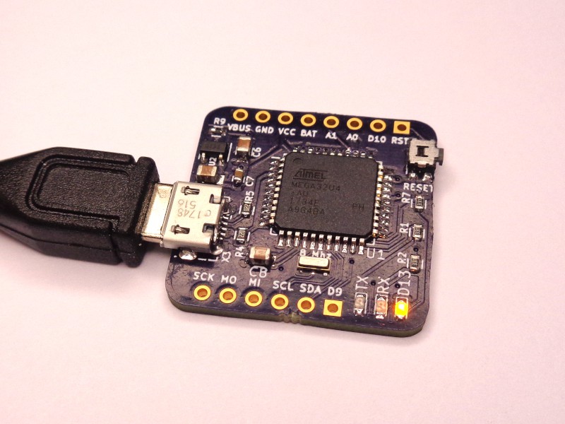
Beetje 32U4 Blok Rev 0.0 Doing the Blink
Since we’ve already admitted to
ripping offborrowing from SparkFun, we might as well use both their 32U4 bootloader (https://github.com/sparkfun/Arduino_Boards) and their instructions for flashing it (https://learn.sparkfun.com/tutorials/installing-an-arduino-bootloader). I placed the ISP header located under the chip and used and my Programming Shield ( https://www.tindie.com/products/MakersBox/yet-another-programming-shield/) with Nick Sayer’s pogo kit (https://www.tindie.com/products/nsayer/avr-isp-pogo-adapter-kit/). There could, in theory, be a dedicated AVR programming blok that would plug into the MCU board to program it, but that is a bit “cart before the horse” at this point.- Rev 0.0 works (see photo) with no bodge wire! The only issue is the ISP marks on the silk screen were swapped. I've fixed that in the board file.
- Rev 0.1 (see rendering) moves the power diodes and polyfuse to the front to make it easier to assemble with reflow. Minor changes to chip positions. No change to header pinouts (yet).
Notes:
- Provisions for 5V operation at 16 Mhz are provided, but haven't been tested.
- I like the right-angle button idea, but not the "feels" of the actual button operation. Any suggestions?
Now, off to design the next blocks for the rocket project and see if this takes off (pun intended) . . .
Beetje Bloks
Build a project bit-by-bit, making it easy to design, debug, and program. Electronics is hard unless you Keep It Simple Stupid.