Josh Starnes
-
Sender Circuits for bracelets or robotic beacons
08/22/2018 at 21:10 • 0 comments![]()
![]()
Sender Circuit to be installed in the bracelets
-
NEC Infrared Transmission Protocol
08/22/2018 at 21:07 • 0 commentshttps://techdocs.altium.com/display/FPGA/NEC+Infrared+Transmission+Protocol
he NEC IR transmission protocol uses pulse distance encoding of the message bits. Each pulse burst (mark – RC transmitter ON) is 562.5µs in length, at a carrier frequency of 38kHz (26.3µs). Logical bits are transmitted as follows:
- Logical '0' – a 562.5µs pulse burst followed by a 562.5µs space, with a total transmit time of 1.125ms
- Logical '1' – a 562.5µs pulse burst followed by a 1.6875ms space, with a total transmit time of 2.25ms
When transmitting or receiving remote control codes using the NEC IR transmission protocol, the WB_IRRC performs optimally when the carrier frequency (used for modulation/demodulation) is set to 38.222kHz.
When a key is pressed on the remote controller, the message transmitted consists of the following, in order:
- a 9ms leading pulse burst (16 times the pulse burst length used for a logical data bit)
- a 4.5ms space
- the 8-bit address for the receiving device
- the 8-bit logical inverse of the address
- the 8-bit command
-
Example RPI code for sending and recieving over IR
08/22/2018 at 21:00 • 0 commentsimport RPi.GPIO as GPIO import math import os from datetime import datetime from time import sleep # This is for revision 1 of the Raspberry Pi, Model B # This pin is also referred to as GPIO23 INPUT_WIRE = 16 GPIO.setmode(GPIO.BOARD) GPIO.setup(INPUT_WIRE, GPIO.IN) while True: value = 1 # Loop until we read a 0 while value: value = GPIO.input(INPUT_WIRE) # Grab the start time of the command startTime = datetime.now() # Used to buffer the command pulses command = [] # The end of the "command" happens when we read more than # a certain number of 1s (1 is off for my IR receiver) numOnes = 0 # Used to keep track of transitions from 1 to 0 previousVal = 0 while True: if value != previousVal: # The value has changed, so calculate the length of this run now = datetime.now() pulseLength = now - startTime startTime = now command.append((previousVal, pulseLength.microseconds)) if value: numOnes = numOnes + 1 else: numOnes = 0 # 10000 is arbitrary, adjust as necessary if numOnes > 10000: break previousVal = value value = GPIO.input(INPUT_WIRE) print "----------Start----------" for (val, pulse) in command: print val, pulse print "-----------End-----------\n" print "Size of array is " + str(len(command))
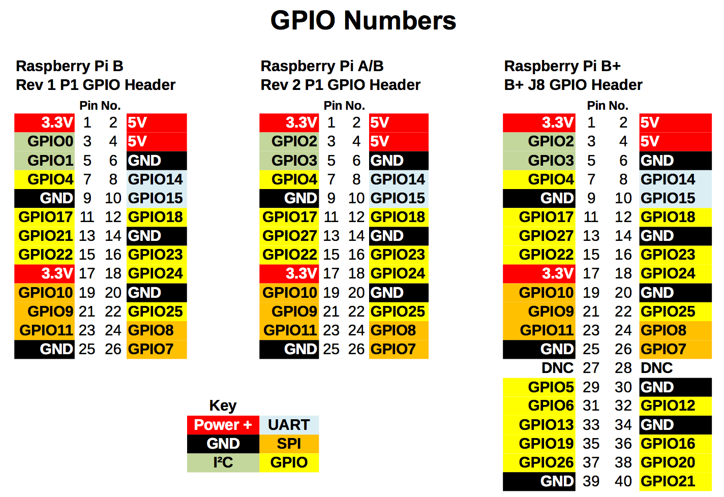
![Raspberry Pi GPIO pin layout for reference. This script uses pin #16, or GPIO23]()
Raspberry Pi GPIO pin layout for reference. This script uses pin #16, or GPIO23
It just runs in an infinite loop, waiting for a 0 to be read from the infrared receiver. It'll then take note of the time and keep reading 0s and 1s, each time making note of how long a run of 1s or 0s was. Once it reads 10,000 1s, it decides the command has probably ended and returns to the top of the loop. 10,000 is arbitrary and could differ depending on your Pi's CPU speed or other factors, so you may need to adjust it. Once the command has ended, the script will print out the pulses and their durations. Here's some sample output when I ran the script and pressed my light switch remote:
0 8982
1 4399

0 631
1 497

0 628
1 1607

0 635
1 490

0 629
1 509

0 627
1 500

0 633
1 500

0 625
1 500

0 624
1 1623

0 629
1 1605

0 622
1 501

0 626
1 1606

0 628
1 1606

0 631
1 499

0 634
1 1605

0 661
1 1569

0 632
1 504

0 626
1 498

0 627
1 1615

0 620
1 496

0 635
1 1614

0 629
1 1599

0 629
1 504

0 625
1 505

0 623
1 516

0 627
1 1598

0 631
1 501

0 625
1 1606

0 627
1 501

0 636
1 496

0 626
1 1609

0 630
1 1606

0 628
1 1607

0 623
I was thrilled to find this matches up very nicely with the NEC protocol! You can see the 9 ms pulse at the beginning, followed by the 4.5 ms gap. The script is off by several hundred microseconds but it's close enough to see what's going on. The next step is to convert this series of pulses to binary.
The basics of the NEC protocol are simple:
- A "logical 0" is a 562.5 microsecond pulse, followed by a 562.5 microsecond gap.
- A "logical 1" is a 562.5 microsecond pulse, followed by a 1687.5 microsecond gap.
Keep in mind that in my pulse list above, a 0 is a pulse, and a 1 is a gap. So to start, chop off the leading 9 ms pulse and the 4.5 ms gap and then read the lines two at a time. The first two entries are:
0 631
1 497
That's a roughly 565 pulse followed by a 565 gap, so this is a 0. Next is:
0 628
1 1607
A 565 pulse followed by a 1687 gap (you can start to see why the numbers don't need to be exact). This is a 1. Next:
0 635
1 490
565 pulse followed by a 565 gap, that's a 0. And so on. Notice the signal also has a trailing 565 pulse at the end. Some signals have this, some don't, but the NEC protocol suggests that the signal should have it. We end up with
01000001101101100101100010100111
I did this one by hand, but for my air conditioning remote, you can imagine it getting tedious. The algorithm to convert these pulses into binary is pretty straightforward and it's simple enough to adapt our Python script to do it for us. We can use the heuristic that any gap over 1000 microseconds is likely a logical 1, otherwise it's a logical 0. Looking at the data, we can see that this is sufficient to distinguish the two. You could even write a cutesy one-liner to convert this "command" array into a binary string:
binaryString = "".join(map(lambda x: "1" if x[1] > 1000 else "0", filter(lambda x: x[0] == 1, command)))
In the script,
commandis an array of tuples of the structure (pulse_value, pulse_duration) where pulse_value is a 0 or 1, and pulse_duration is an integer in microseconds. We filter this array to only include the gaps (x[0] == 1) because the gap is what distinguishes a 1 from a 0. Then we map all gaps with a duration (x[1]) greater than 1000 to be a "1", otherwise a "0". All those 1s and 0s are then joined together to form the binary string.If we group this binary string into bytes, we can see the structure of the signal a little more easily:
01000001
10110110
01011000
10100111
One thing the NEC protocol mentioned is that the second byte should be the inverse of the first, and the fourth byte an inverse of the third. At first I thought I did something wrong, but it turns out my remote doesn't follow the standard. So that's great! We decoded the signal, and it even looks like an NEC protocol infrared signal. At this point, to test that I decoded it correctly, I wanted to run the command through LIRC (Linux Infrared Remote Control). This package lets you define static commands in hexadecimal in a config file, and then you can send them from the command line.
Here's the conversion of the binary string to both decimal and hex
Binary      Decimal      Hex
01000001    65           41
10110110    182          B6
01011000    88           58
10100111    167          A7

Final: 0x41b658a7
Sending the IR signal
In order for infrared to work properly, you need a pretty consistent 38 kHz signal to be generated. That means you need to go through an entire on/off cycle every 1/38000 seconds, or roughly every 26 microseconds. That's no problem, you think. Even the first Raspberry Pi had a 700 MHz CPU, more than fast enough to change a pin on and off at 38 kHz. But you don't get all that 700 MHz to yourself. You have to run the OS, which takes quite a sizable chunk of that processing speed away. Then you have the fact that you're running Python, an interpreted language that might run a garbage collector at any time, delaying your code unpredictably. And even a compiled program written in C or C++ could be interrupted by the operating system, as your program is not the only thing running and the OS will stop your program to give other programs a chance to run. So you might get the correct speed with C, but the OS interruptions means you won't get a consistent wave, and thus the signal won't work, or it won't work reliably.
-
PI zero and IR circuits
08/22/2018 at 18:57 • 0 commentsExample of IR transmitter using PI, I would use Pi Zero I believe.
http://www.raspberry-pi-geek.com/Archive/2015/10/Raspberry-Pi-IR-remote
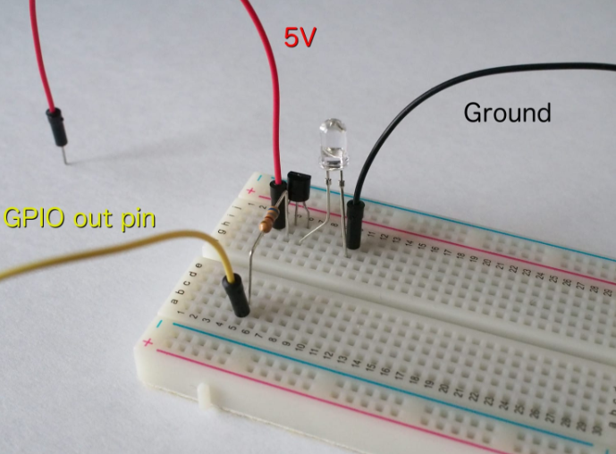
Building and Testing an IR LED Circuit
Although you can connect an IR LED directly to GPIO pins on the Raspberry Pi, the LED's output signal will be too weak, and the IR transmitter will have a very limited range. A simple transistor circuit solves the problem by amplifying the current output from a pin and thus increasing the IR LED's signal strength.
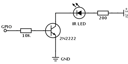
To build a transistor-powered IR transmitter, you need two resistors (220ohm and 10K), a transistor (2N2222, BC547, or practically any other transistor will do), and a 940nm IR LED. Additionally, you'll need a breadboard and jump wires to assemble an IR transmitter prototype (Figure 1). Wire the components as shown in Figure 2 to assemble the IR transmitter. The next step is to check to see whether the IR transmitter actually works. To do this, you can use a simple LED Python blinking script (Listing 1) that turns the LED connected to pin 22 on and off.
![]() Figure 1: Transistor-powered IR transmitter schematics.
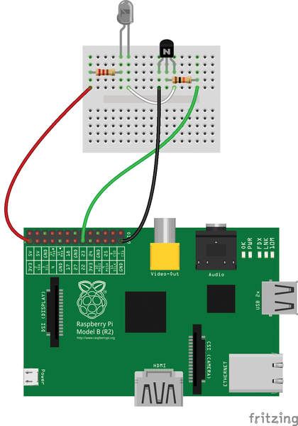
Figure 1: Transistor-powered IR transmitter schematics.![]() Figure 2: Wiring diagram.
Figure 2: Wiring diagram.Listing 1
Python Blinking LED Script
01 #!/usr/bin/python
02 import RPi.GPIO as GPIO
03 import time
04 GPIO.setwarnings(False)
05 GPIO.setmode(GPIO.BCM)
06 GPIO.setup(22, GPIO.OUT)
07 while True:
08     GPIO.output(22, True)
09     time.sleep(1)
10     GPIO.output(22, False)
11     time.sleep(1)
Because the IR LED is not a regular light-emitting diode, how do you actually find out whether it blinks or not? You can use a camera with an LCD screen or smartphone camera. Point the camera at the circuit and look at the screen. If the circuit works, you should see the IR LED blinking.
Installing and Configuring the LIRC Package
To control a device with an IR receiver, the IR LED transmitter must send a specific signal sequence, and the LIRC package [1], which emulates the infrared signals of many remote controls, is the perfect tool for the job. LIRC is available in the Raspbian software repositories, so installing it on Raspberry Pi is just a matter of running
sudo apt-get install lirc
Once you've done that, you need to enable and configure the
lirc_rpikernel module. To do so, openmodulesin the Nano editorsudo nano /etc/modules
and add the lines below to the file:
lirc_dev
lirc_rpi gpio_out_pin=22
Make sure that the
gpio_out_pinparameter points to the pin controlling the IR LED (in this case, it's pin 22). Next, open the file/etc/lirc/hardware.confin Nano as before withsudoand add the following configuration to the file:LIRCD_ARGS="--uinput" LOAD_MODULES=true DRIVER="default" DEVICE="/dev/lirc0" MODULES="lirc_rpi" LIRCD_CONF="" LIRCMD_CONF=""
Now, reboot the Raspberry Pi using the
sudo reboot
command to activate the configuration. Finally, you need to specify a profile that emulates a specific remote control. The project's website [2] offers a long list of profiles that emulate practically any remote control in existence, including remote controls for DSLR cameras. So, if you want to use Raspberry Pi to control a Nikon D90 DSLR camera, point the browser to lirc.sourceforge.net/remotes/nikon/ML-L3 and copy the profile. Next, open the
/etc/lirc/lircd.conffile in Nano, paste the copied profile into it, save the changes, and restart LIRC with:sudo /etc/init.d/lirc restart
Turn on the DSLR camera and enable the IR triggering mode. On your Raspberry Pi, issue:
irsend SEND_ONCE Nikon2 shutter
If everything works properly, your camera should fire.
-
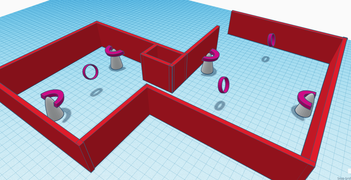
3D representation
08/22/2018 at 18:46 • 0 commentsHere is the 3D representation of receivers places in rooms that can pickup IR signals from the IR bracelets in the home, as little as 2 , one on each end of the room to pickup signals regardless of the direction you are standing.
![]()
![]()
-
Researching products and other projects
08/22/2018 at 13:53 • 0 commentshttps://www.aplaceformom.com/blog/4-29-15-dementia-and-elderly-gps-tracking-devices/
https://create.arduino.cc/projecthub/projects/tags/tracking?page=1
https://www.ncbi.nlm.nih.gov/pmc/articles/PMC4970021/
https://www.ibm.com/blogs/internet-of-things/sensors-smart-home/
https://www.ncbi.nlm.nih.gov/pmc/articles/PMC3354997/
https://www.ncbi.nlm.nih.gov/pmc/articles/PMC5982638/
https://www.ncbi.nlm.nih.gov/pmc/articles/PMC5750778/
http://modernroboticsinc.com/ir-seeker-v3-2
https://blog.bschwind.com/2016/05/29/sending-infrared-commands-from-a-raspberry-pi-without-lirc/
-
in the beginning
08/22/2018 at 13:25 • 0 commentsSo this project is the spawn of my semifinalist project, QR IR code navigation for robots. I always wanted a way to interface discretely with my home and home devices. In my mind we must compromise the environment of machines and the environment of humans. Making processes simpler makes way for practicality and usefulness. Not only can a IR bracelet allow machines to better track humans, it can be used as tracking to prompt facial recognition, emotion recognition and gesture control as well. I will post any links i find for research and proceed from there.
IR Wearable Human/pet tracking and Gesture Control
Humans and Pets wear small invisible beacons that allow robots and smart homes to track and easily recognize humans and pets