-
Debugging the Receiver
12/28/2018 at 05:15 • 0 commentsI've had a few people struggle with the receiver, so I wanted to write a guide to clarify how it works and how to test it.
The NRF on the receiver is constantly waiting to receive packets from the 2 transmitters on the Dichotomy boards. When it gets a packet, it updates it's internal memory (storing the matrix info, mouse movement, etc), and continues waiting. As often as it's able, the arduino (running QMK) requests that info from the NRF, which is sends over UART.
Because the arduino is at 5v and the NRF is at 3.3, there is a level shifter chip in between so nothing gets fried. This is the small, difficult-to-solder 8-pin IC underneath the NRF. Most of the time when there's an issue with the receiver, it can be traced to this.
That said, try the below steps to debug things:
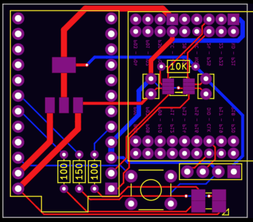
1) Ensure all solder joints are good (none of the 8 pins on the small IC should have continuity with each other when everything is off/unpowered, but they SHOULD all have a continuity with another part on the board. Follow the traces to see where. Here's a picture:
![]()
2) Ensure you've flashed the receiver with QMK. If you need more details on this one, I suggest going to the QMK Discord Channel.
3) Make sure your USB cable is working - some cables work for charging (powering) things, but don't have the necessary data lines to actually facilitate communication. If your cable works for another keyboard, it should work for this.
4) If QMK is running, try using the hid_listen tool available here:
https://www.pjrc.com/teensy/hid_listen.html
If the arduino and NRF are having trouble communicating, you should get a lot of "Time out in keyboard" messages. If you don't see that, either (1) your arduino isn't running QMK, or (2), the NRF and arduino are communicating fine, but the NRF isn't receiving any packets from the transmitters.
5) Loopback test:
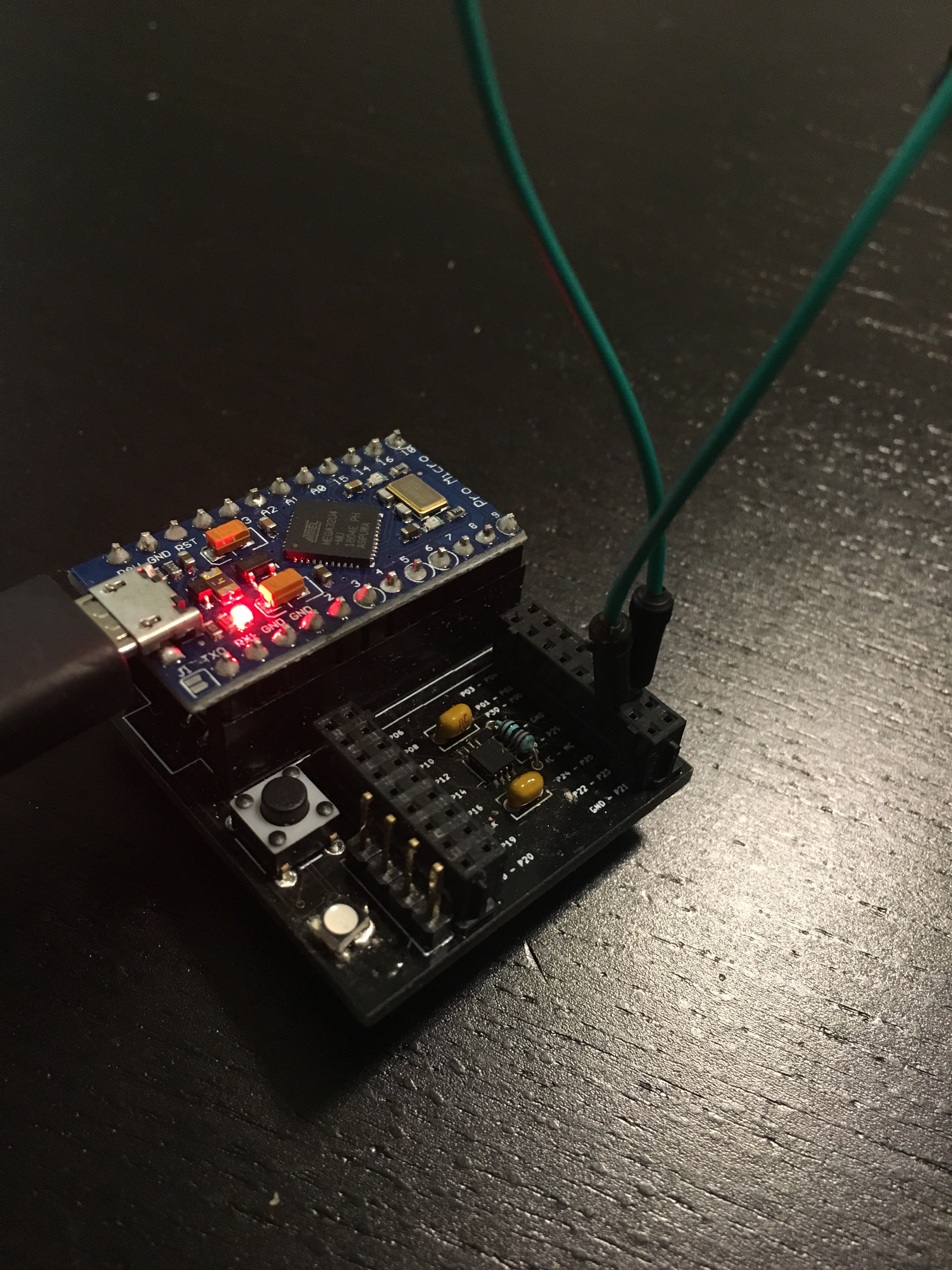
If you're seeing a lot of "time out in keyboard" in the previous step, we need to see if the 8-pin IC is soldered correctly or not. We can do this by looping any data we send back through. First, remove the NRF and insert a jumper into your receiver like so:
In case the picture is hard to make out, that's the 3rd-from-last hole in each of those rows, and that is 1 jumper, so we're bridging those two ports. Also ignore the LED, it's oriented incorrectly in this picture (this was an old version of the board, but most of it's still the same).
Once that's inserted, upload the following arduino sketch (I used the arduino IDE and the "Leonardo" board definition - I had to press the reset button twice before uploading):
void setup() {
  Serial.begin(9600);
  Serial1.begin(1000000);
  //Serial.write((uint8_t)(F_CPU>>8));
  //int received;
  //int sent;
}

void loop() {
  while (!(Serial.available())){
    //wait.
  }
  int received = Serial.read();
  uint8_t uart_data = 0;
  Serial1.write(received);
  uint32_t timeout = 0;
  while (!(Serial1.available())){
    timeout++;
    if (timeout > 10000){
      Serial.write("\r\nTime out in keyboard.");
      break;
    }
  }
  if (Serial1.available()){
    uart_data = Serial1.read();
  }
  Serial.write("\r\n UART is ");
  Serial.write(uart_data);
  Serial.write("\r\n");
}
Once it's running, open up the serial monitor and try sending anything. I sent "test," and got back this:
 UART is t

 UART is e

 UART is s

 UART is t
If that works, then your IC is soldered correctly, and the problem is apparently the NRF. It's either fried, or running the wrong program. A guide to reprogram the NRF will be up soon.
If instead, you get something back like:
Time out in keyboard.
 UART is

Time out in keyboard.
 UART is

Time out in keyboard.
 UART is

Time out in keyboard.
 UART is
Then it's likely that your 8-pin IC (bi-directional level-shifter) is either (1) fried, or (2) not soldered properly, or (3) both of the above.
Hopefully this was helpful - let me know if you have any questions, the discord (invitation/link sent out in the last Group Buy update email) is a great place - or comment here.
-
Receiver Assembly!
12/11/2018 at 05:18 • 0 commentsI'm shipping out the GB kits, and I thought I should PROBABLY upload the instructions for assembly. I've got a video (currently rendering) for the board, but the receiver was simple enough that I decided to do it with pictures.
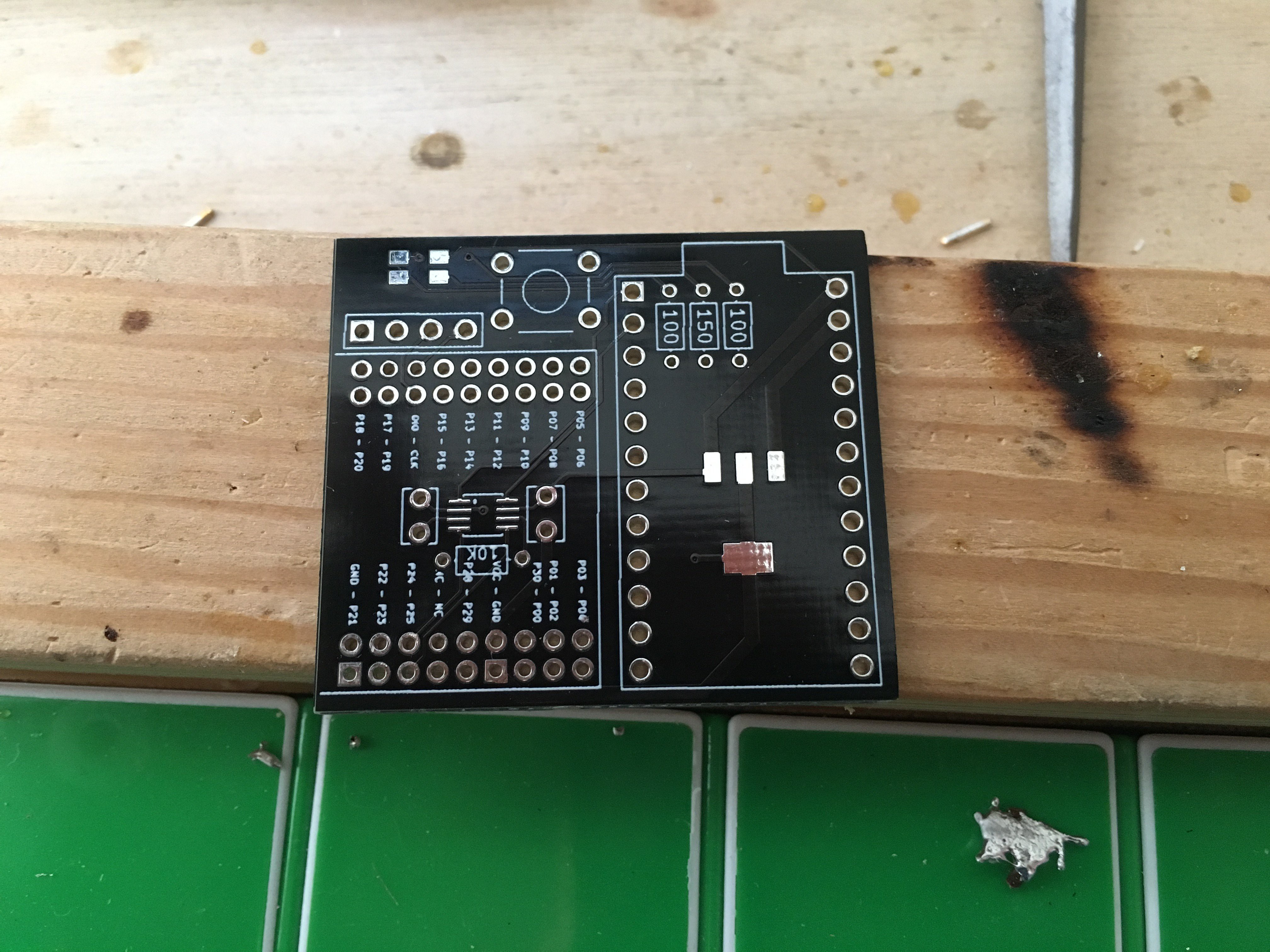
Note: The receiver PCB pictured is an older version, but it's VERY similar to the one I shipped. The main differences are: (1) on the 8-pin package (the very first thing soldered), the pictured version has a single dot to indicate orientation. The new version of the board, which shipped, has a line across the top (like the IC does). (2) The LED orientation was slightly wrong (I was using an old footprint on this one). For the PCBs that were shipped, there is a small triangle on the silkscreen of the PCB by the LED footprint. Align that triangle with the triangle mark on the top of the LED.
Let's go!
This first picture is the bare receiver board. Please note the changes between the version pictured and the version that actually shipped. We'll be soldering on the 8-pin package near the center-ish of the board. It's got a white stripe along the top that will help you identify how to orient it (hint: match it with the white line on your PCB).
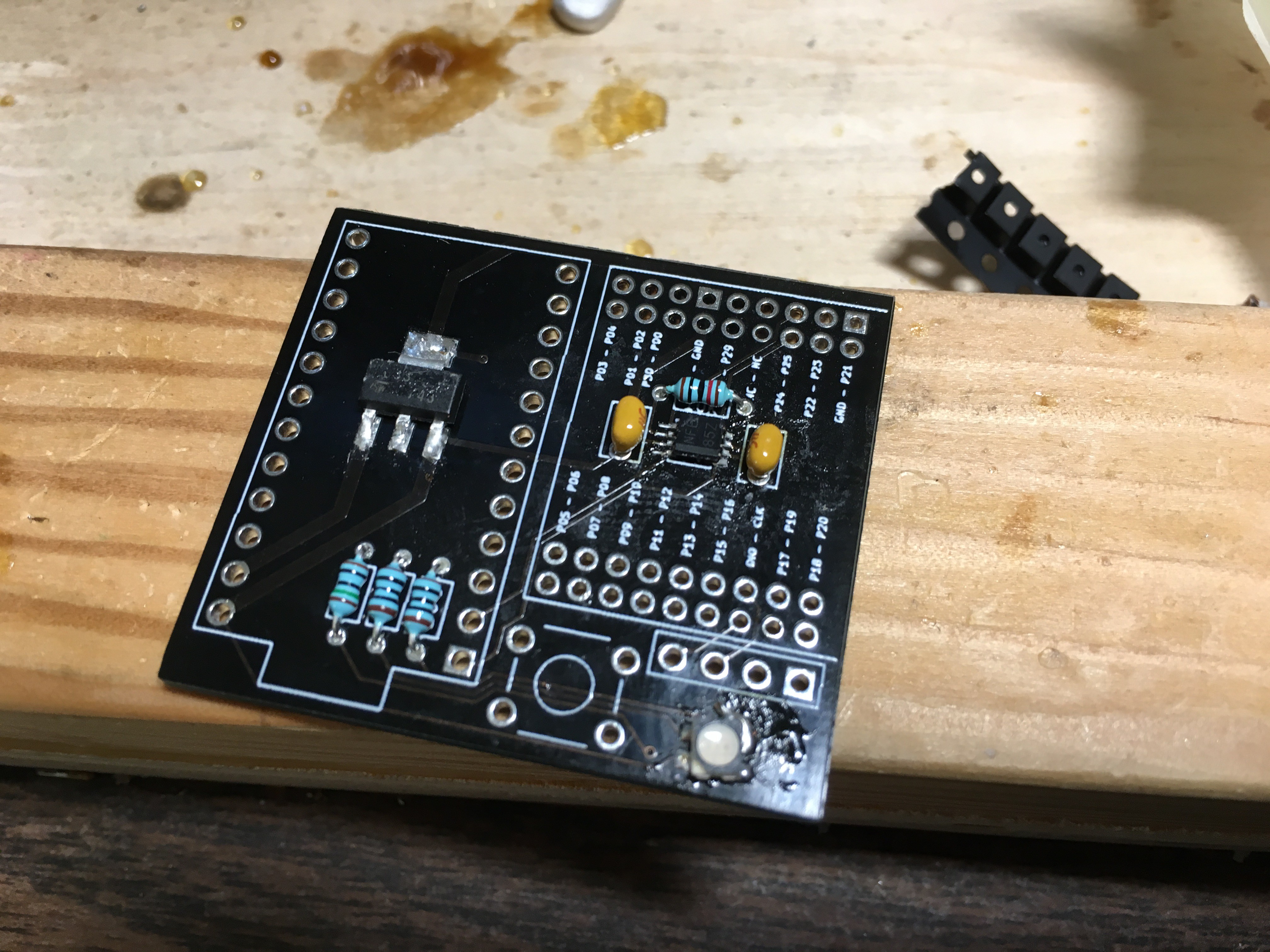
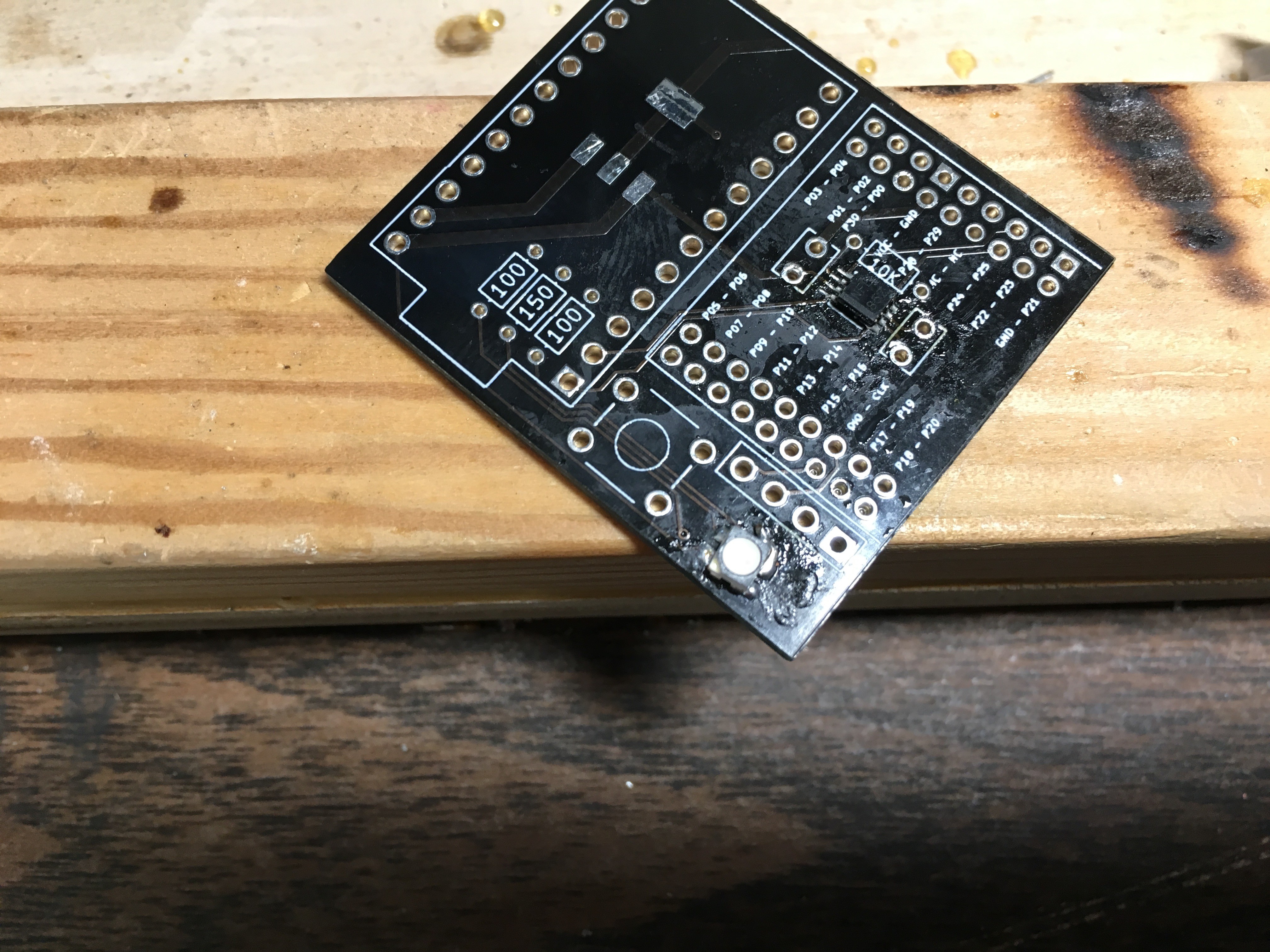
There we go, all soldered. Try not to clog the capacitor holes (you can see I ignore my own advice if you look at the hole to the bottom-right of the IC we just soldered). Next, we'll be soldering on the LED. Again, my board (the one in the picture) and the boards I shipped have slight differences. The board YOU have should have a small triangle in one corner of the LED footprint. Align the triangle on your LED with the triangle on the board. Don't do what I did.
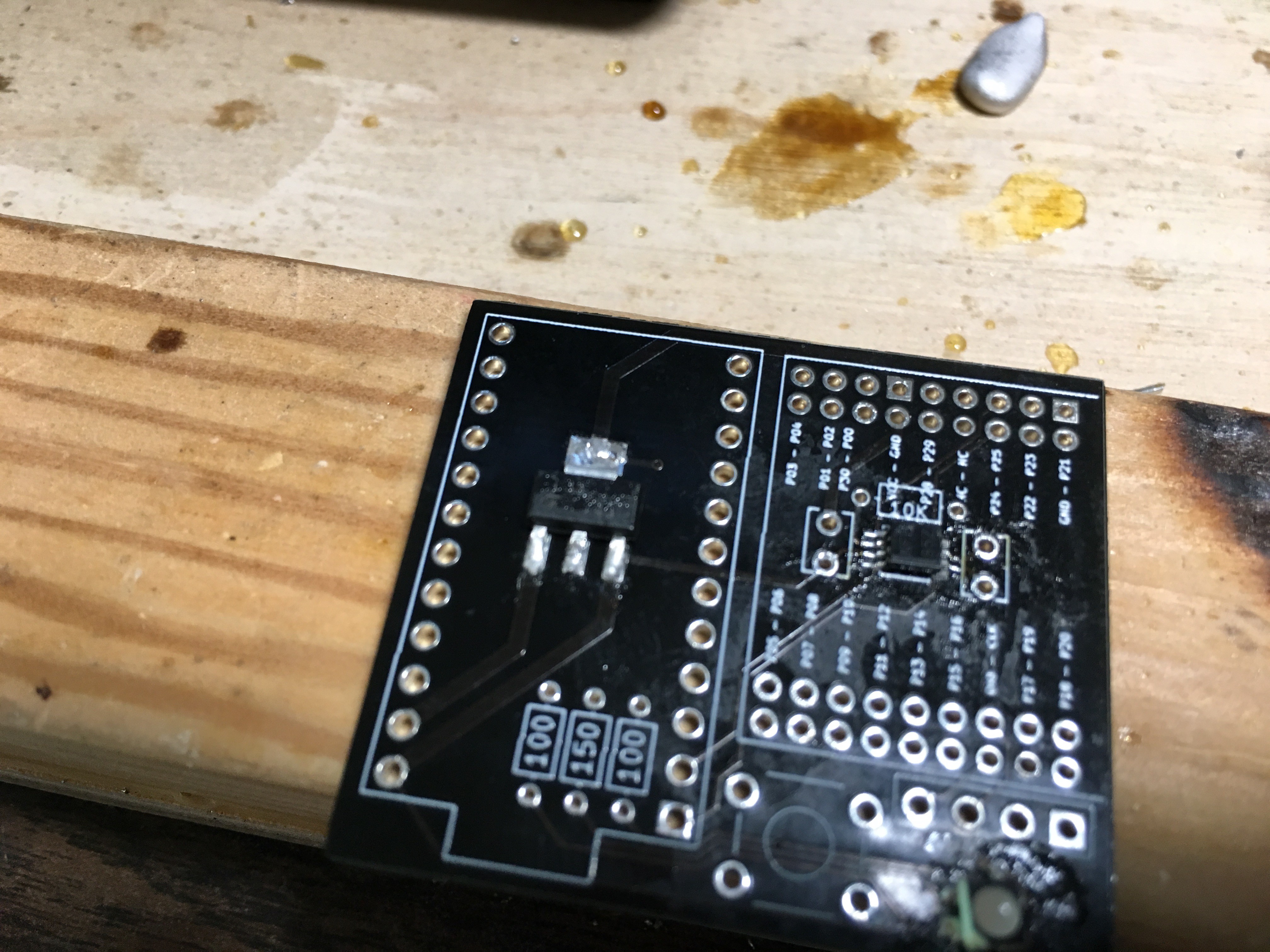
Great! Assuming you did it right. If you didn't do it right, not great. Next we'll get on the linear regulator - there's only one place/orientation it could possibly go:
Now we'll get on the resistors and capacitors. Another deviation (WHY AM I EVEN POSTING THESE INSTRUCTIONS?) from the picture to your board: I put my resistors (the three that are right next to each other) in the "wrong" places. The brown-green-black-black should go in the MIDDLE of the three, and should be flanked by brown-black-black-blacks. The brown-black-black-red is the 10k, and should go by the 8-pin IC we soldered earlier. Neither the resistors nor the capacitors are directional, so you can flip them around however you want.
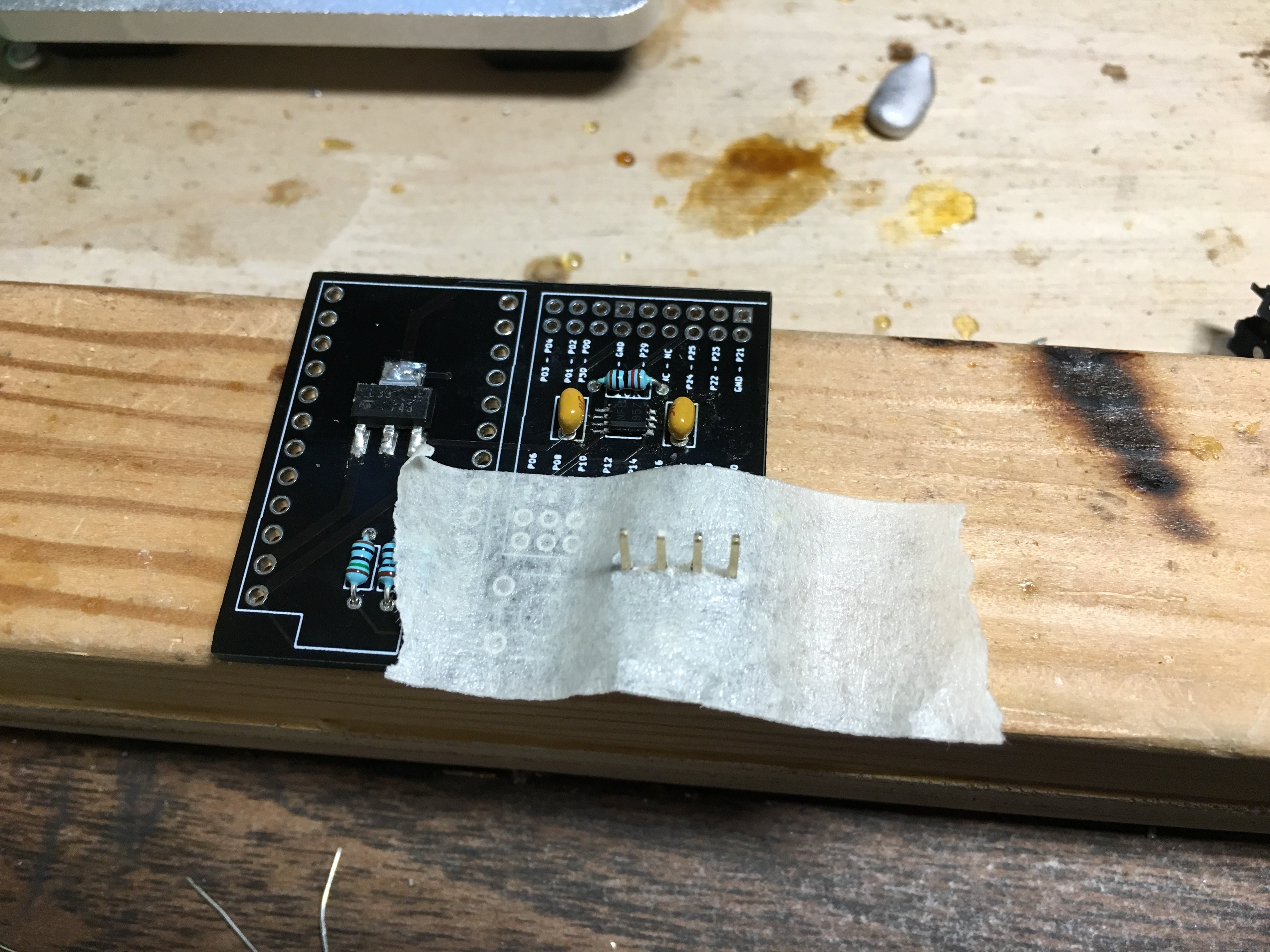
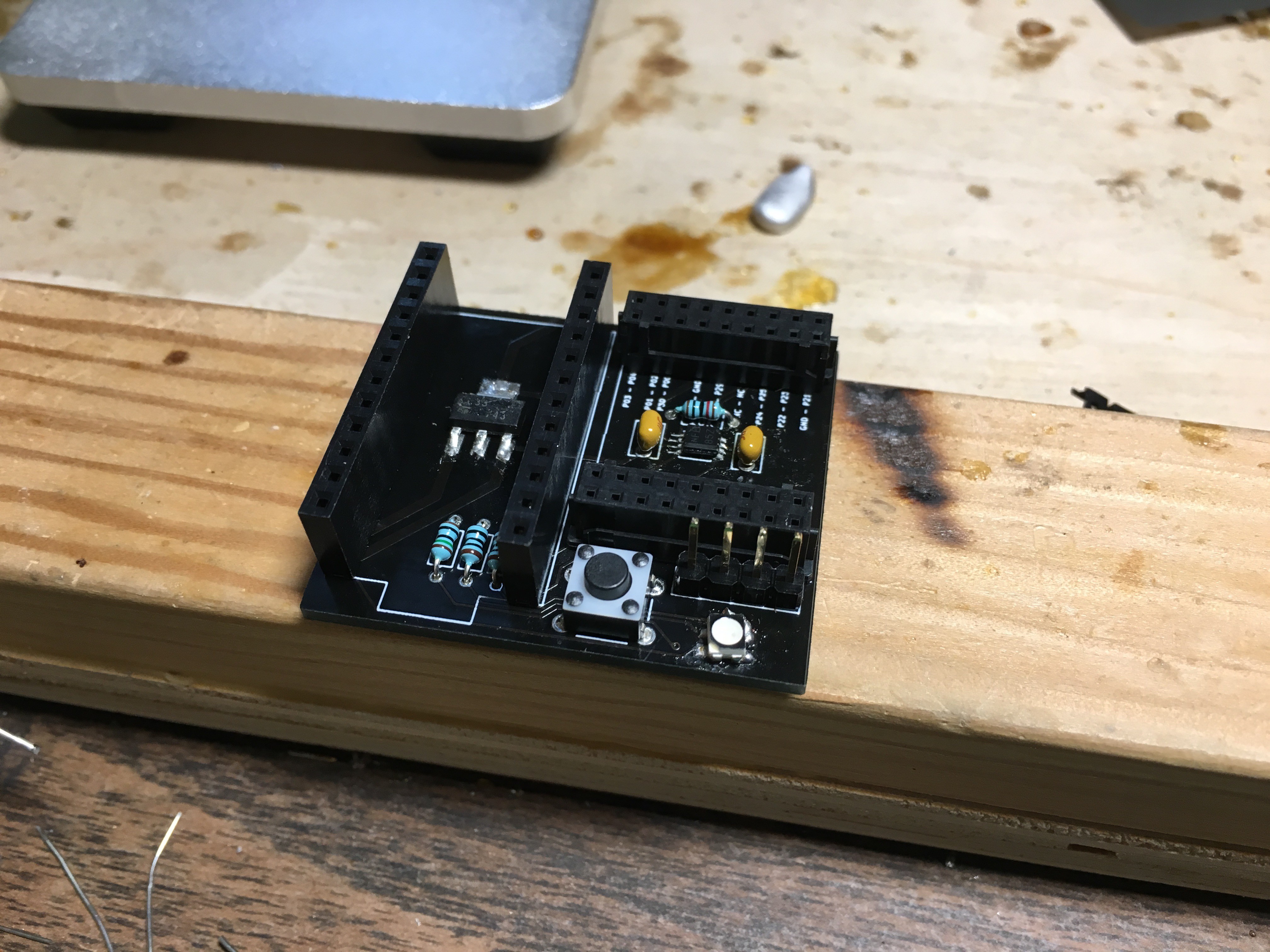
Perfect. Now the 4-pin header:
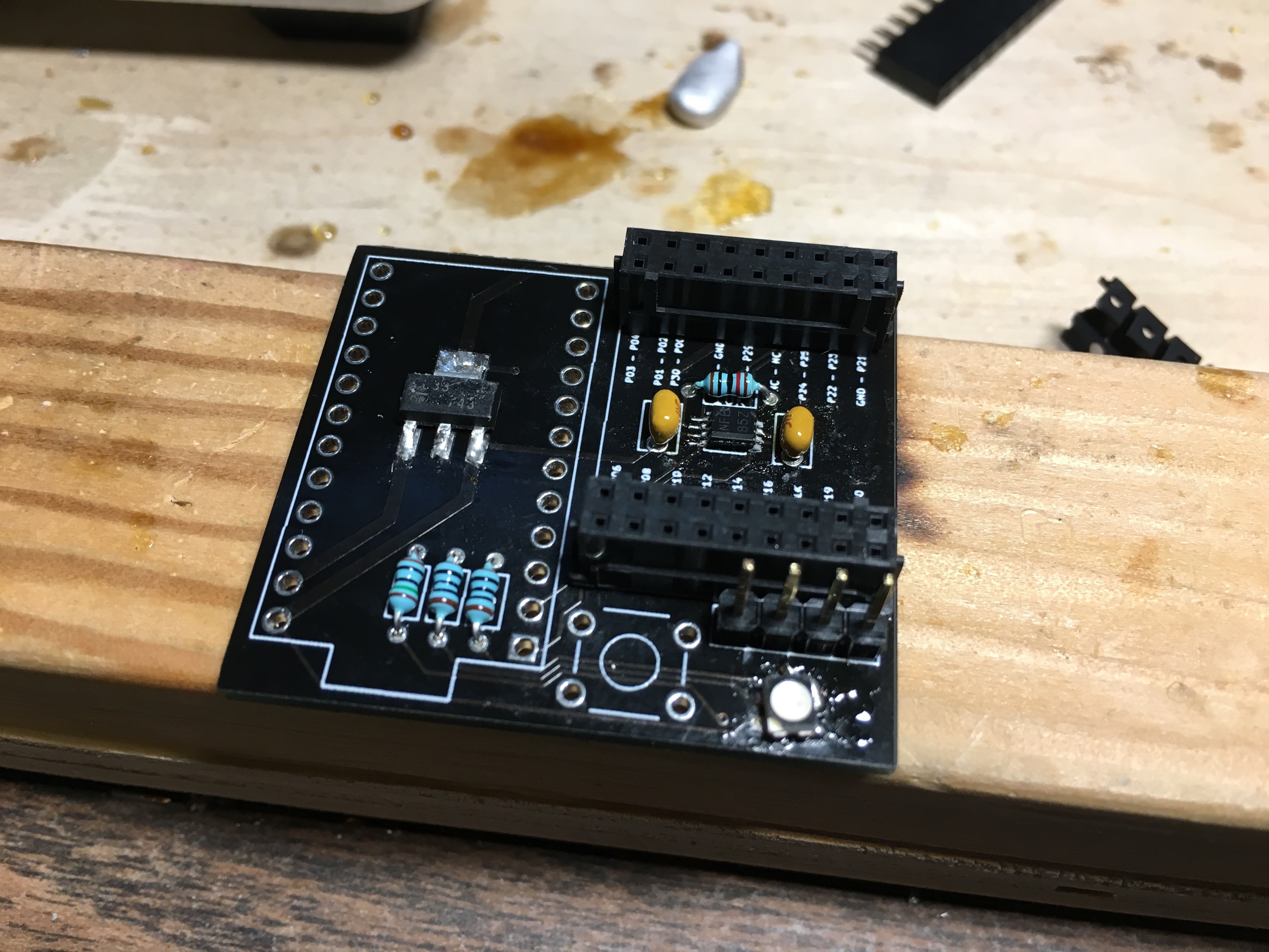
Aaaand the two 18-pin headers for the NRF:
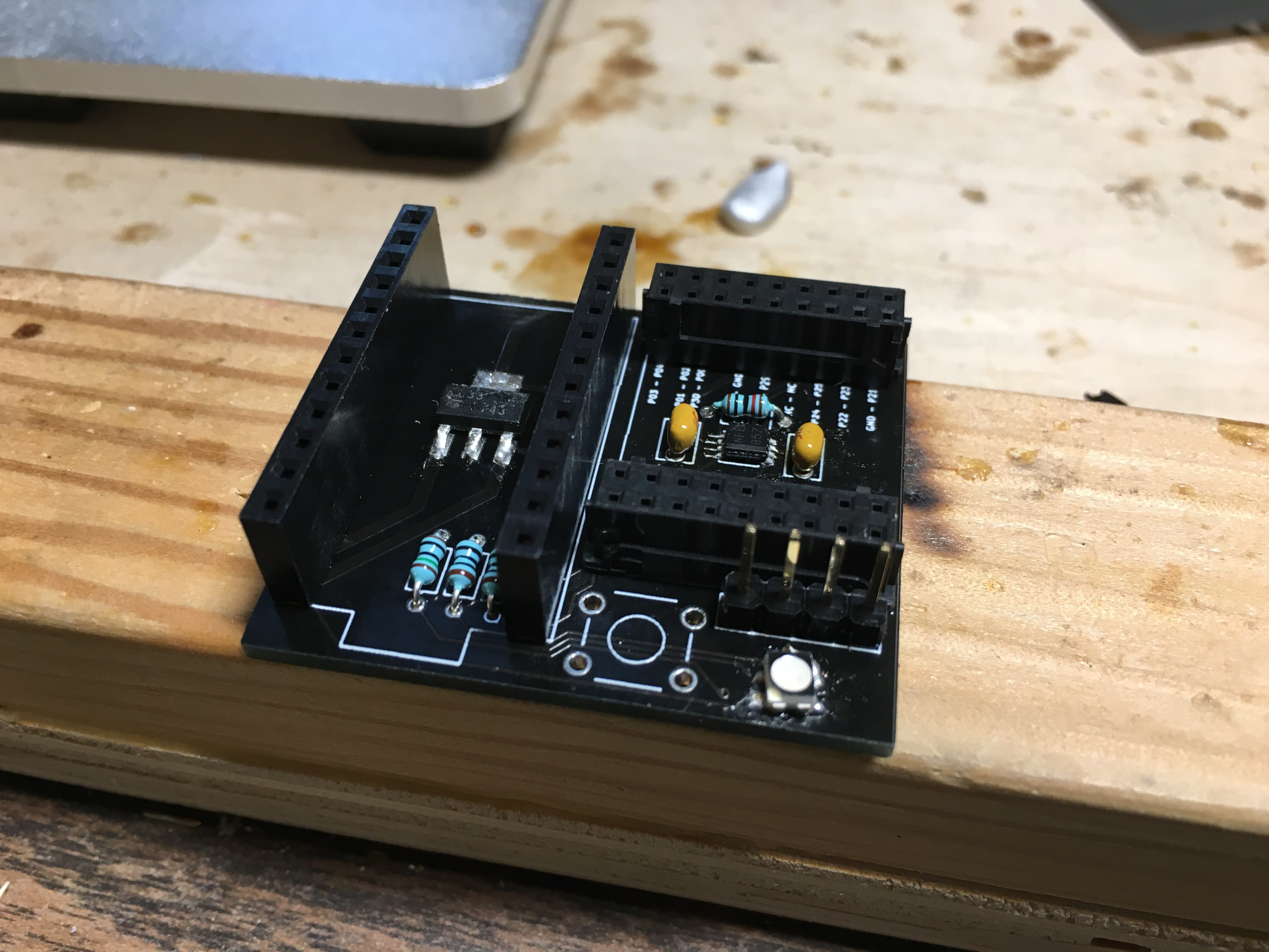
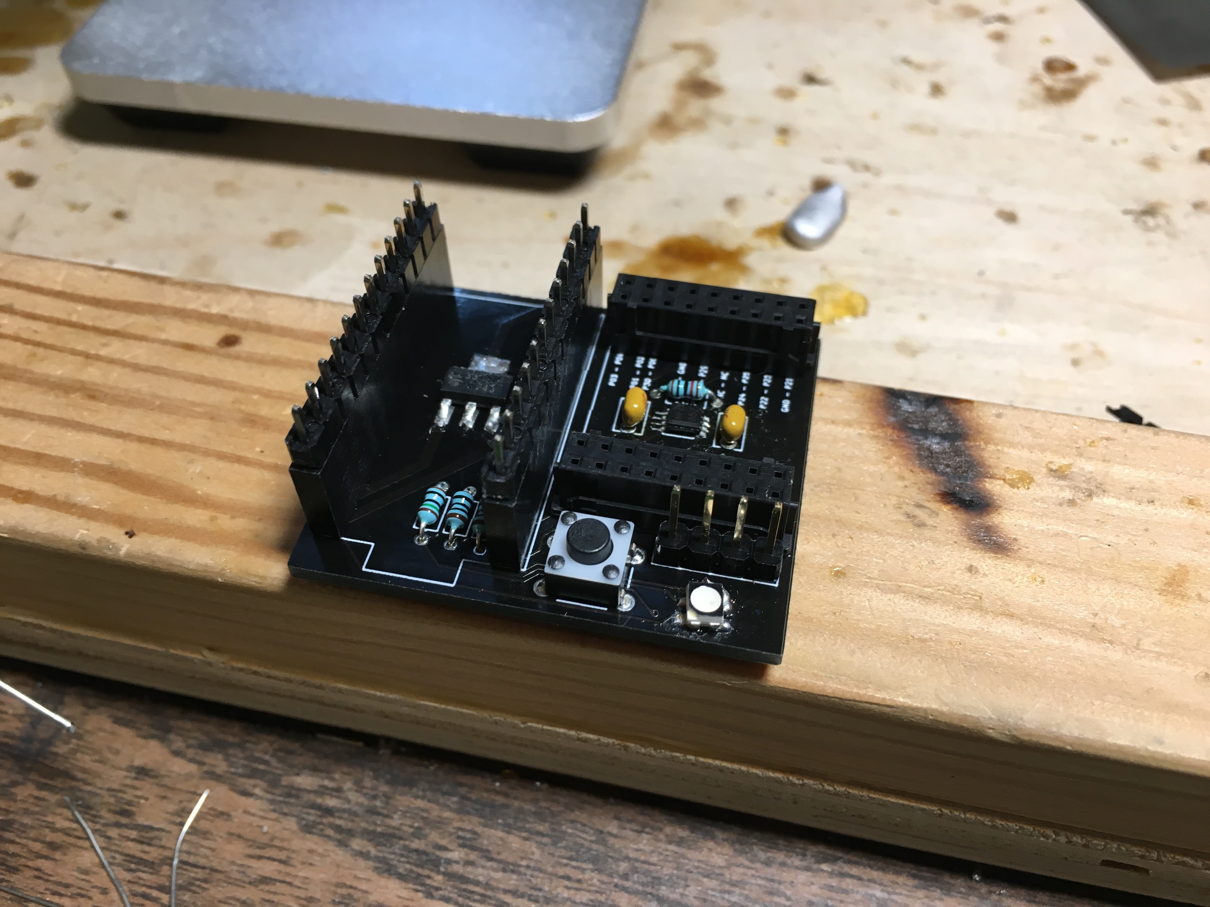
The two 12-pin headers for the Pro Micro:
And the tactile switch:
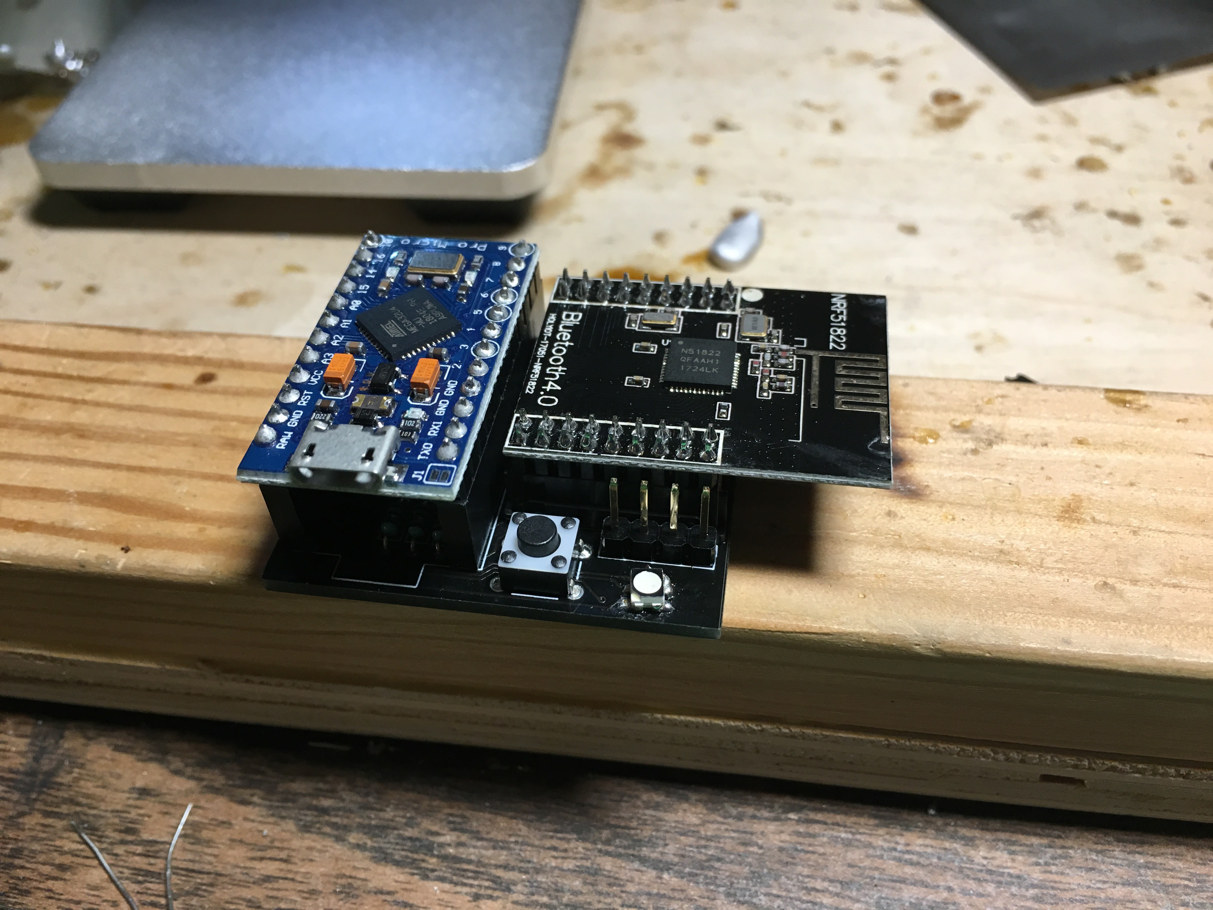
If your pro micro isn't already inserted, I recommend inserting it into the headers to solder it, to ensure it's got the right alignment.
Insert everything, and you're all done!
Yay, being all done. Video for the board assembly coming soon!
Dichotomy - Keyboard and Mouse
The keyboard. The mouse. Tragically separated since birth. Finally rejoined in "Dichotomy."
 Joshua Broekhuijsen
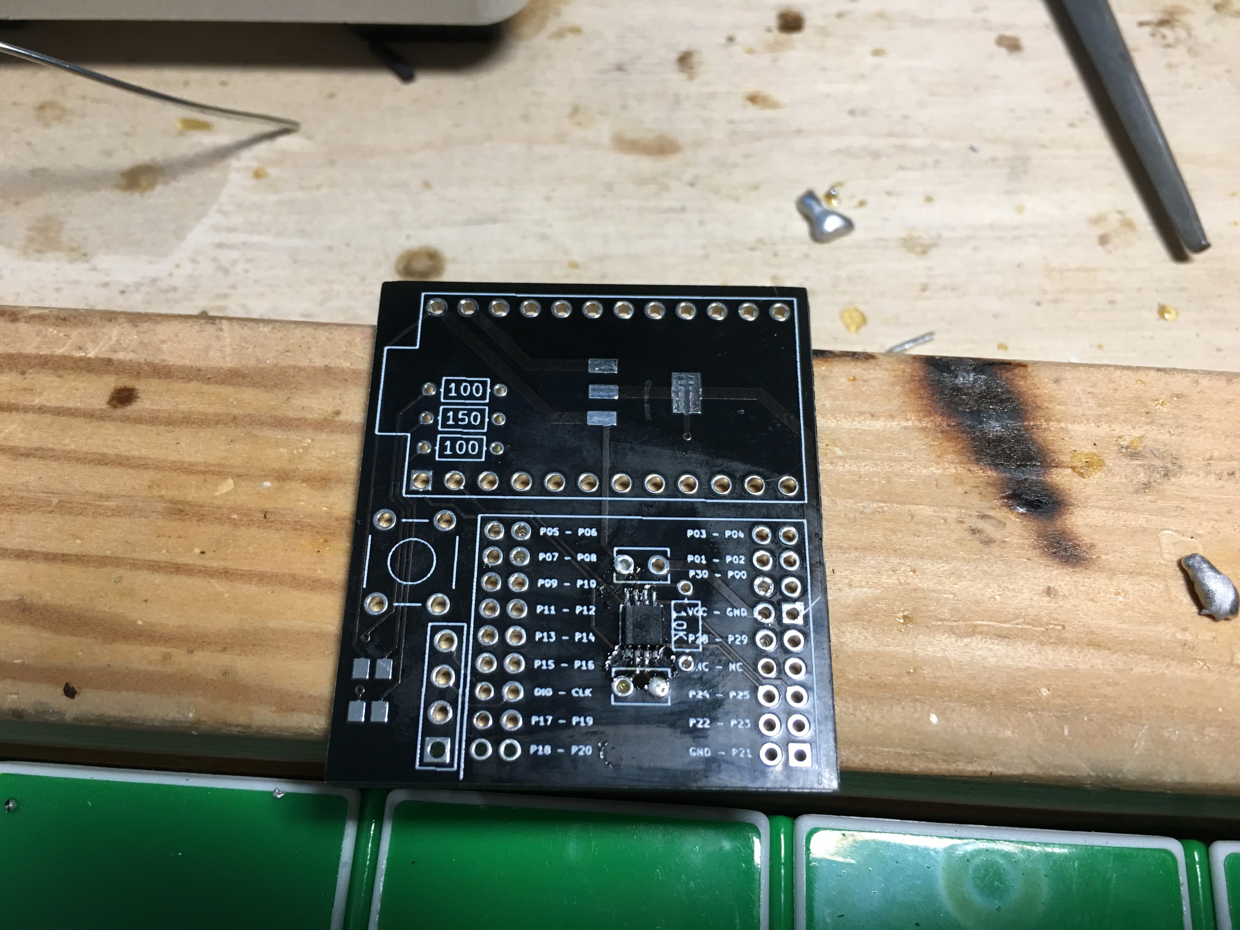 There we go, all soldered. Try not to clog the capacitor holes (you can see I ignore my own advice if you look at the hole to the bottom-right of the IC we just soldered). Next, we'll be soldering on the LED. Again, my board (the one in the picture) and the boards I shipped have slight differences. The board YOU have should have a small triangle in one corner of the LED footprint. Align the triangle on your LED with the triangle on the board. Don't do what I did.
 Now we'll get on the resistors and capacitors. Another deviation (WHY AM I EVEN POSTING THESE INSTRUCTIONS?) from the picture to your board: I put my resistors (the three that are right next to each other) in the "wrong" places. The brown-green-black-black should go in the MIDDLE of the three, and should be flanked by brown-black-black-blacks. The brown-black-black-red is the 10k, and should go by the 8-pin IC we soldered earlier. Neither the resistors nor the capacitors are directional, so you can flip them around however you want.