-
1Download Arduino IDE
Before starting with building anything you should make sure your computer can communicate with the Adalogger M0 board and that you can flash sketches to it. This should reduce frustration later. Start by installing the Arduino IDE.
-
2Install relevant Arduino boards to run the Adalogger M0
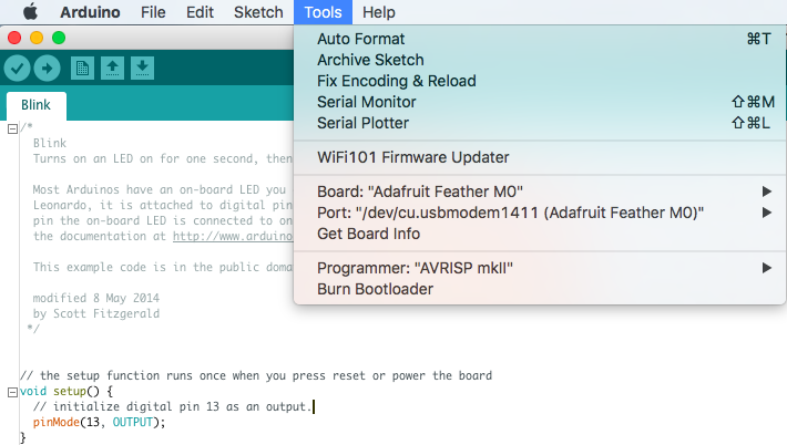
The Adafruit M0 Adalogger board is not natively supported by the Arduino IDE. Follow instructions here to install support for this board in the Arduino IDE. After completing these steps make sure you can flash the example sketch "Blink" to the Adalogger board before continuing. To do this, open the Blink example in File>Examples>Basic>Blink.
"Double-click" the small physical button on the Adalogger board to put it in bootloader mode, set Board to "Adafruit Feather M0" and port to the correct COM port and click upload (the right arrow at the top of the Arduino IDE). You should see "Upload complete" in the bottom feedback window and the red LED on the board should blink once per second.
Congratulations, you have configured your Arduino IDE and uploaded a sketch to the Adalogger!
-
3Install relevant libraries
The PIR device requires the following libraries:
#include <Adafruit_SSD1306.h>
#include <Wire.h>
#include <RTCZero.h>
#include <SPI.h>
#include <SdFat.h>
#include <Adafruit_GFX.h>
These are available for download as a single zip file from the files area, or you can search for them online. When you're done they should all be in your libraries directory, see example:
If this doesn't work, or you'd prefer a different way go through instructions here for how to manually add libraries.
-
4Download PIR sketch and extract it
Extract the PIR device sketch (also in the files area) to where ever you like to keep Arduino sketches (for me it's: /Documents/Arduino).
Open the PIRCounter*.ino file in the Arduino IDE and flash this code to the M0. You should see "Upload complete" at the bottom of the IDE. Nothing will happen yet, but this confirms that you have all libraries installed correctly.
-
5Download 3D housing and print it
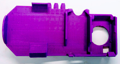
Download 3D housing (also available in the Files area) and print it.
-
6Prepare short 3 wire connection cable
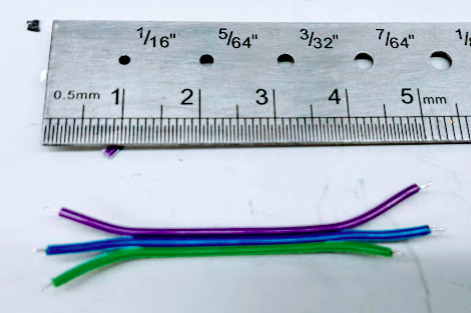
Cut a 5cm piece of 3-wire cable. Strip ~2mm from end of each wire and tin the ends.
NOTE: Cut one wire (green below) about 1cm shorter than the rest, this is not critical but it will make the wiring a bit cleaner at the end.
-
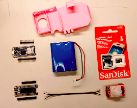
7Assemble and lay out all needed parts
-
8Put male headers on the OLED shield and female headers on the Adalogger board
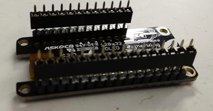
You can lay out several at once if you want. I found it easiest to first put the male headers on the OLED shield:
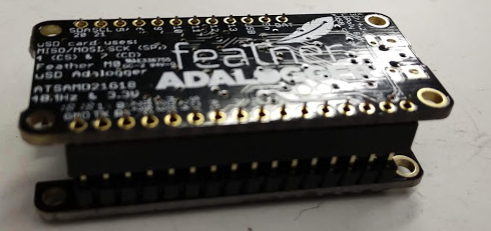
And then turn it over and put the female headers on the Adalogger board.
NOTE: Be careful to leave the shields a bit loose before soldering the Adalogger headers, so you don't solder everything together.
-
9Solder connector cable onto the PIR sensor
We chose this PIR because it is very low power (gives more battery life). It has >10x lower power consumptions than some of the others we piloted, which is critical for extending battery life, as this sensor is always on. That said, you can use this design with any PIR that provides a digital output.
Unfortunately, the Olimex PIR module doesn't provide a digital output pin. To get around this, we soldered directly onto the LED output and use that as our signal. We give it power (3V) and ground by soldering onto the relevant pins in the photo. You can leave the signal LED in place or remove it.
-
10Solder the PIR to the OLED shield
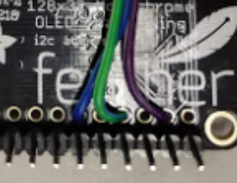
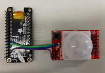
Solder the power, ground, and signal pins to the proper holes on the OLED shield.
The OLED shield doesn't have printed labels, so align it with the Adalogger to see the connection. Or just count - Power is the 2nd hole from the bottom (3V on the Adalogger), under the "h" in feather, ground is the 4th hole between the "a" and the "t" (GND on the Adalogger), and signal is under the "e" (A1 on the Adalogger).
That's it for soldering!
RAD (Rodent Activity Detector)
Using a passive infrared sensor and a datalogger to record activity patterns from rodent home cages
 Lex Kravitz




Discussions
Become a Hackaday.io Member
Create an account to leave a comment. Already have an account? Log In.