So, I handed the belt synth to my friend Brandon to see if he could figure out the strange audio issue with the LED making noise in the speaker.
His solution was to isolate the audio section ground from the rest of the circuit.
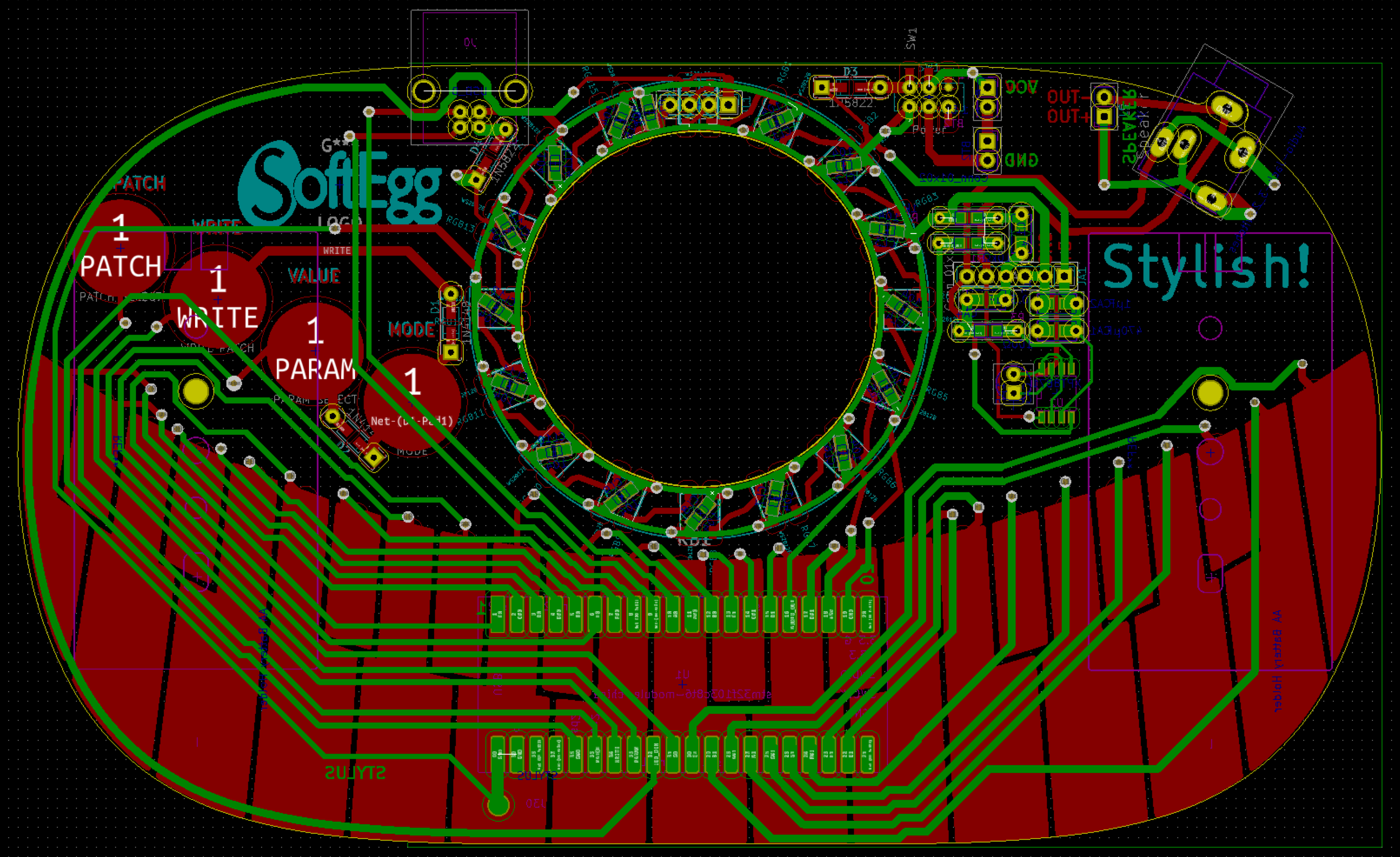
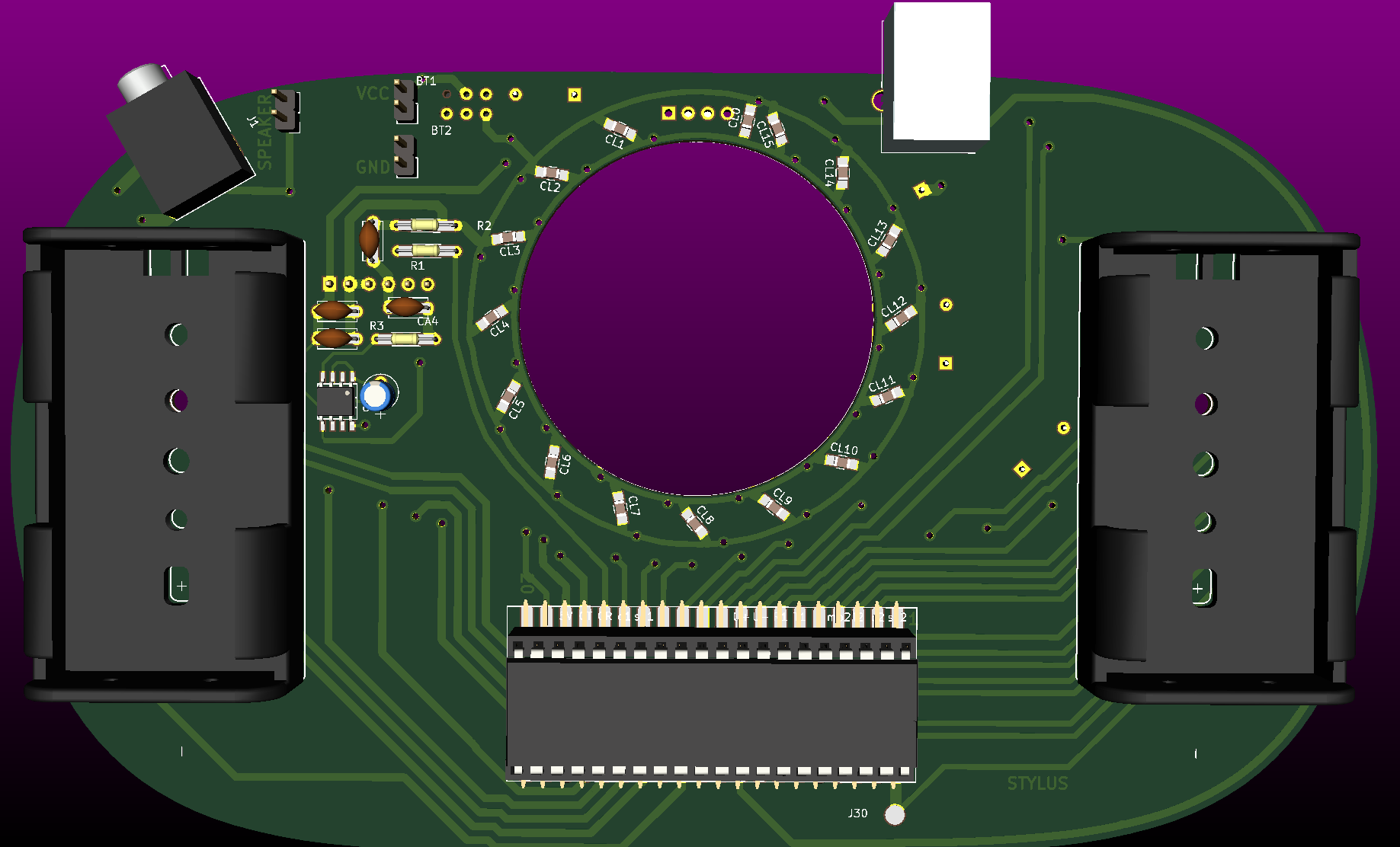
You can do this by cutting the traces on the GROUND (battery) side of C1 on both sides of the board so that they don't connect anything, and then running a bodge wire to the exposed conductive pad at the back of the amplifier chip (the exposed rectangle with the 6 vias on the right of the board, when you are looking at the front.)
You also cut the connection between C4 and GROUND (battery) so that the only connection is to the back of the potentiometer terminal 1.
It seems odd, because the ground at the amplifier is still connected to the battery by a longer route, but somehow this seems to work.
I have a nice picture of what to do, but I keep getting "Unknown Error" trying to upload it, so I can't show it.
Anyway, I've updated the KiCAD schematics and PCB on my system, so I'll probably try to test them before making them public.
I wonder how to specify the bodge wire in the PCB tho?
Does anybody know what the best way to cut traces on a PCB is? I have ~60 to correct...
I'm kinda way behind on project logs, but I submitted this project to the DigiKey "Making Tech At Home" contest, since, well, I'm making them at home right now.
Since all the files are on GitHub, anybody else can make one too. You may think "Oh, it requires a fancy PCB and all sorts of surface mount parts from China!" but really, all you need is a blue pill (STM32F103C8T6) board, and maybe an LED ring or LED strip with WS2812B parts in it.
The whole thing was designed to be fairly modular, and was originally prototyped with a blue-pill, an LED ring, and the cheapest amplifier board on AliExpress, and early board revisions (see the history on GitHub) actually have pin connectors for those parts.
But even if you just have the STM32 blue-pill board, you can still make a playable synth pretty easily:
You can replace the PCB + stylus "keyboard" with a bunch of switches, or even recode to use a keyboard from something else, using a keypad library or something. The only strange thing with the keyboard is that there are a couple of diodes so that you can use the last button (pad) to trigger two buttons at once, which was a poor man's way of multiplexing and getting one more button in.
While I have an elaborate low pass filter to eliminate the PWM noise, you can literally just attach it to a headphone jack or amplifier input and it will probably sound OK, since those things can't reproduce frequencies in the PWM range anyway.
You can power it through the USB port on the blue-pill board and skip the batteries and extra diodes.
Again, the LEDs can be replaced with just about any commodity WS2812B LED ring or LED strip.
Basically, the software is the synthesizer, and with the code from this project, any Blue Pill board can become a valid synthesizer.
Since it is based on Mozzi, you could probably even run it on a Teensy or Arduino Duo with a little effort. Patch storage / writing would probably have to be reconfigured, but most other platforms have some persistent memory for storage and don't require you to write to the Flash as I have done.
And that is why I think this is appropriate for the DigiKey "Making Tech At Home" contest. One microcontroller, and you can basically make a completely usable, programmable synthesizer.
I lost the LED ring somewhere between the Supplyframe Design Lab and 23b Shop in Fullerton.
Then, having returned home late, I accidentally left Stylish on the car seat and it melted in the heat of the day! Oh noes!
Worse, I need it to show off at Hackaday Superconference, as I won an award for it!
Well, Friday is a lost cause. It does still work, so I brought it, but it looked terrible!
I can reprint it, but it takes 27 hours! What to do?
Well, the back is still vaguely shaped correctly, so if I just print the front, it might be OK. That's only 8 hours...
Ok. And Alex Whittemore volunteered to print the back, so I sent them the link for the files for that, although I imagine it won't be done before he has to leave for the show, so I won't get it til Sunday in any event.
But what to do about the LED ring?
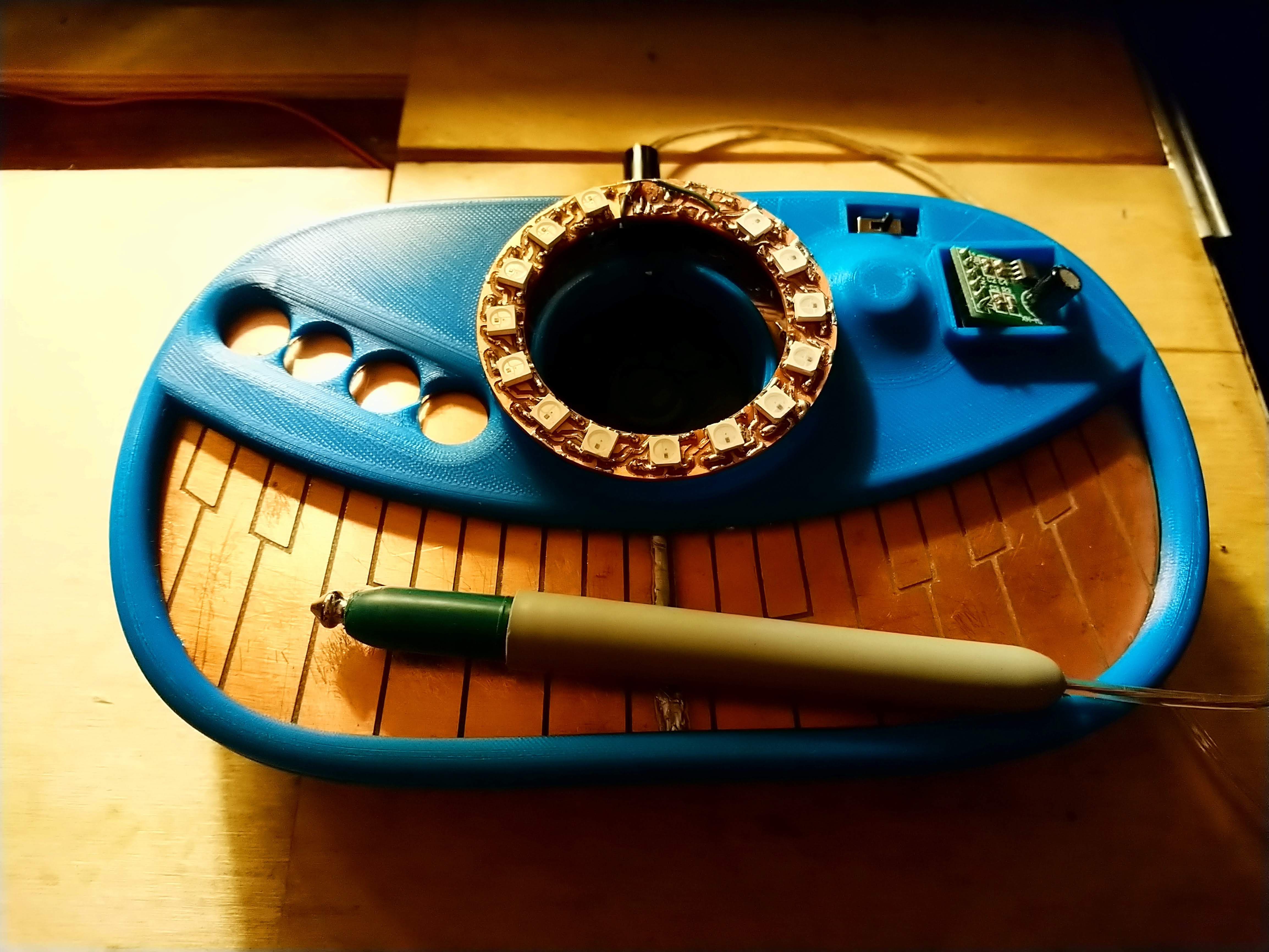
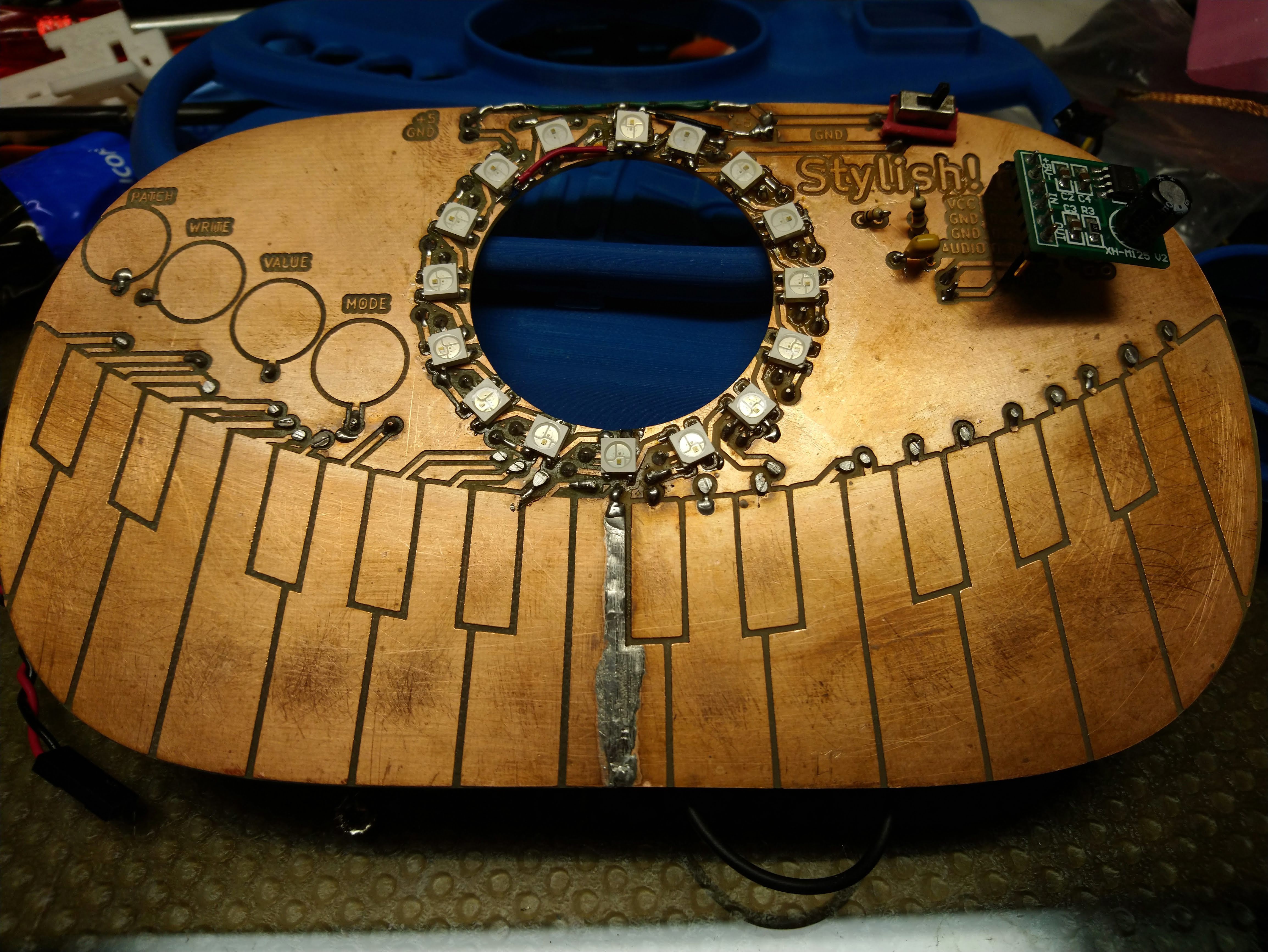
Well, there ARE traces on the PCB to solder it on directly, but two of the LEDs traces were kinda messed up, so I used the external ring instead.
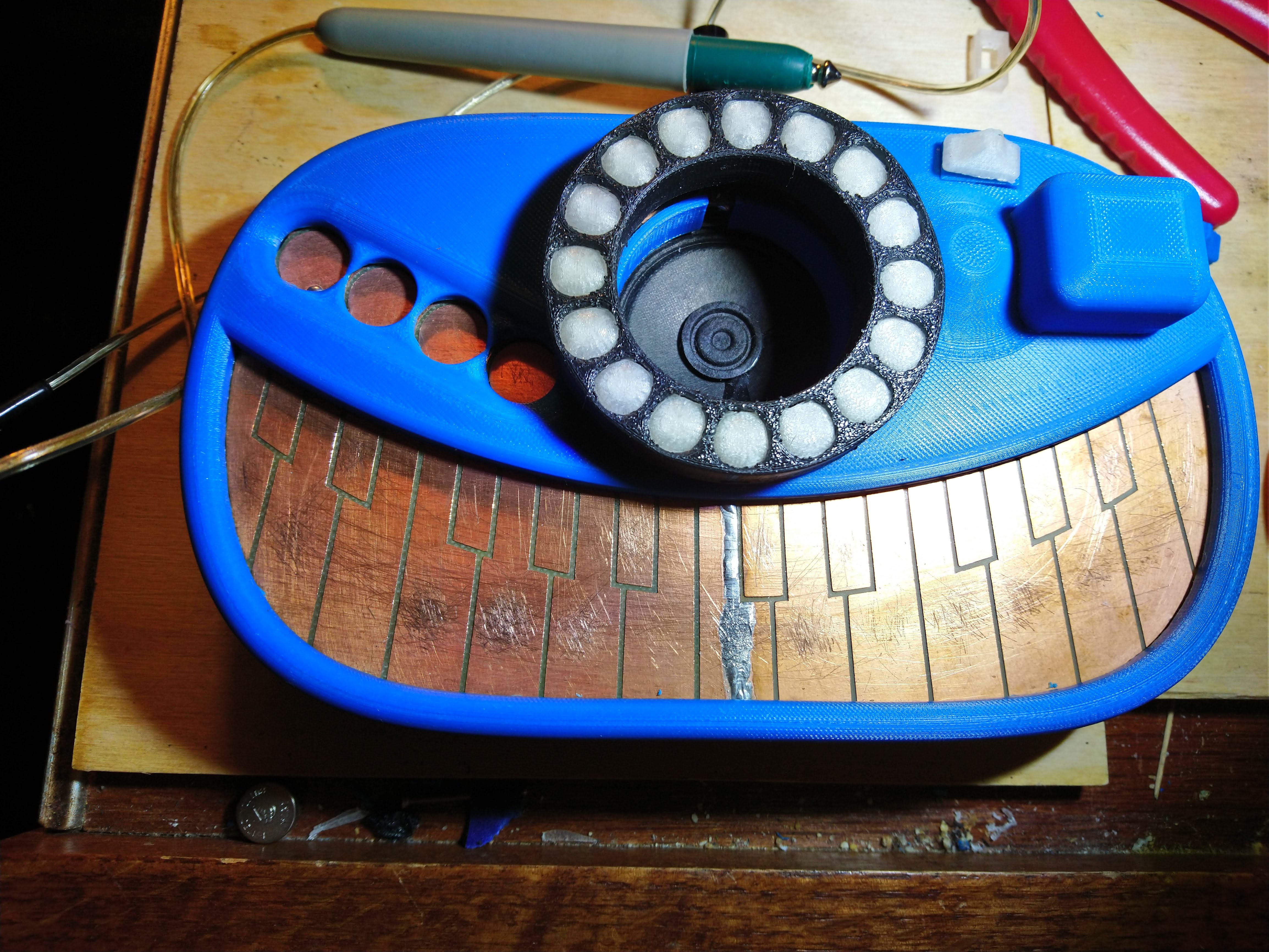
Well, nothing to it but to do it. I soldered all of the WS2812B RGB LEDs to the board, using lots of bodge wires to fix the places where the traces were incorrect.
It took some debugging, as there was one bad LED in the bunch that had to be replaced, and I had to wire one LED completely floating in the air...
It can still be a little finicky, and the last LED has some strange extra colors in it, but it's good enough for show!
I also have a spare of the white part of the LED bezel, although I don't have the TPE part. I can reprint that Saturday night.
So I should have something decent for tomorrow's show.
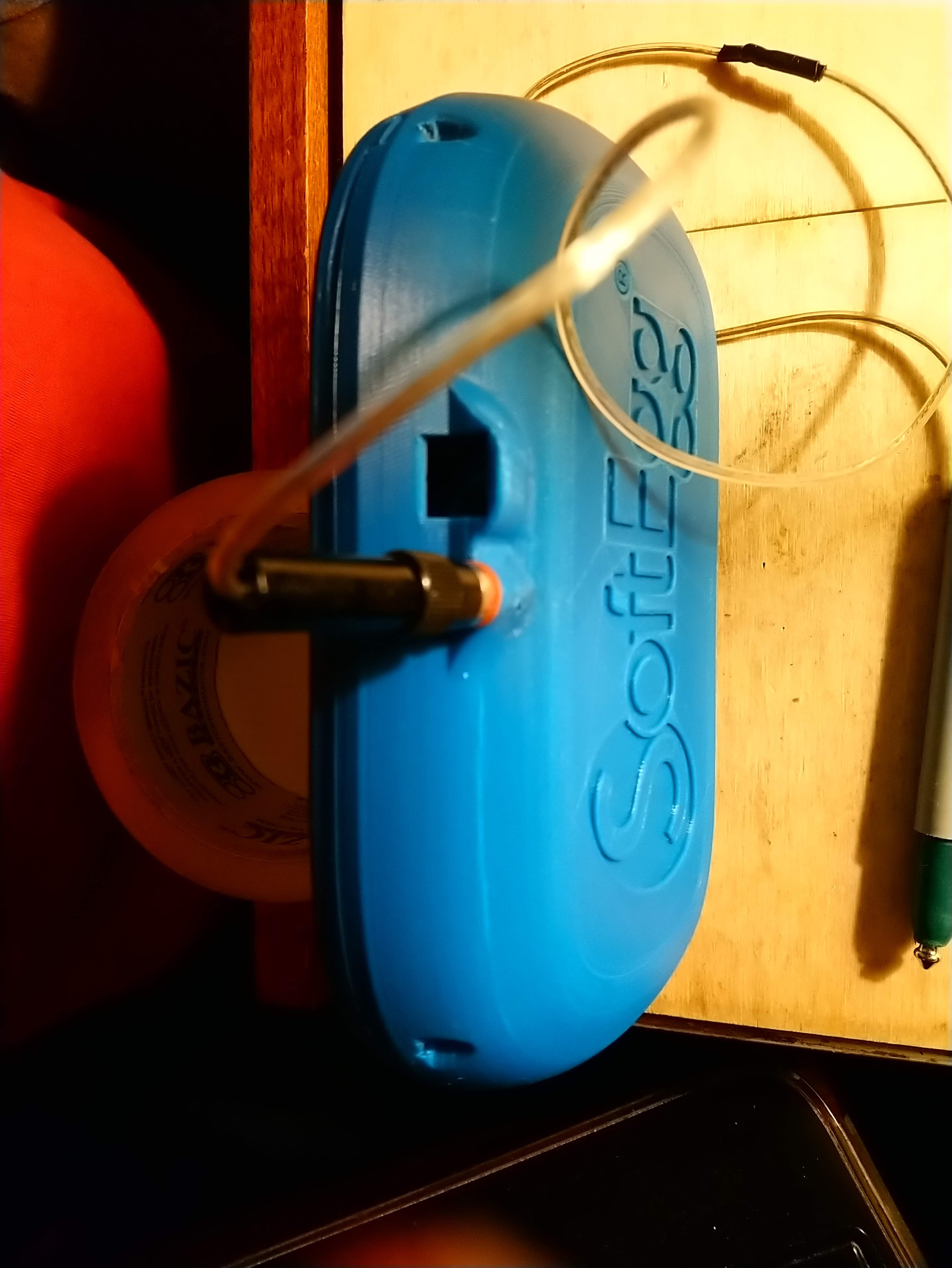
So, the prototype was looking pretty decent, but it still had some noticeable holes around the LED ring, power switch, and the amplifier board.
Also, the belt synth should probably have a way to mount it on your belt.
I know, right?
So anyway, I spent a night doing CAD and 3d printing stuff.
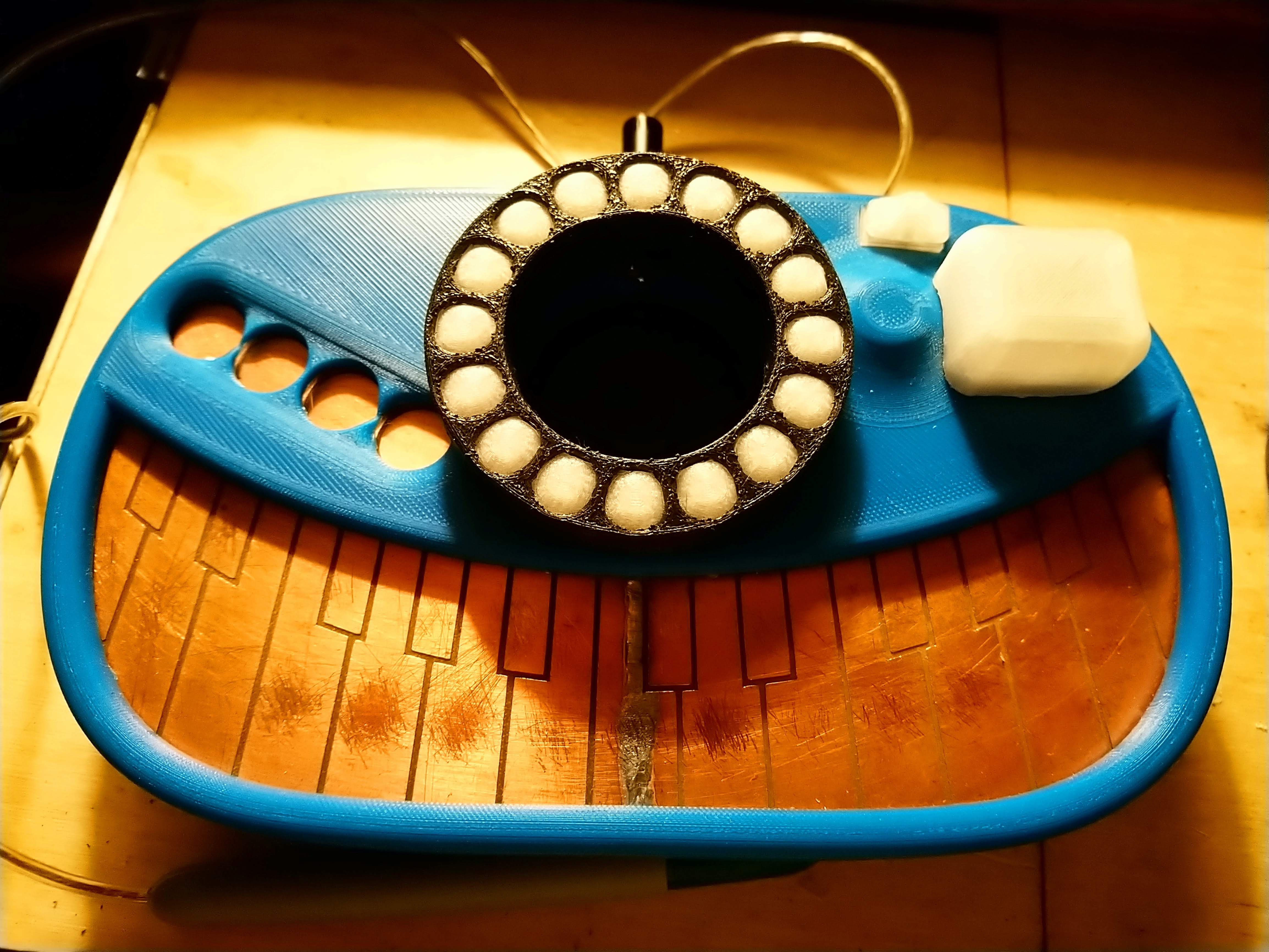
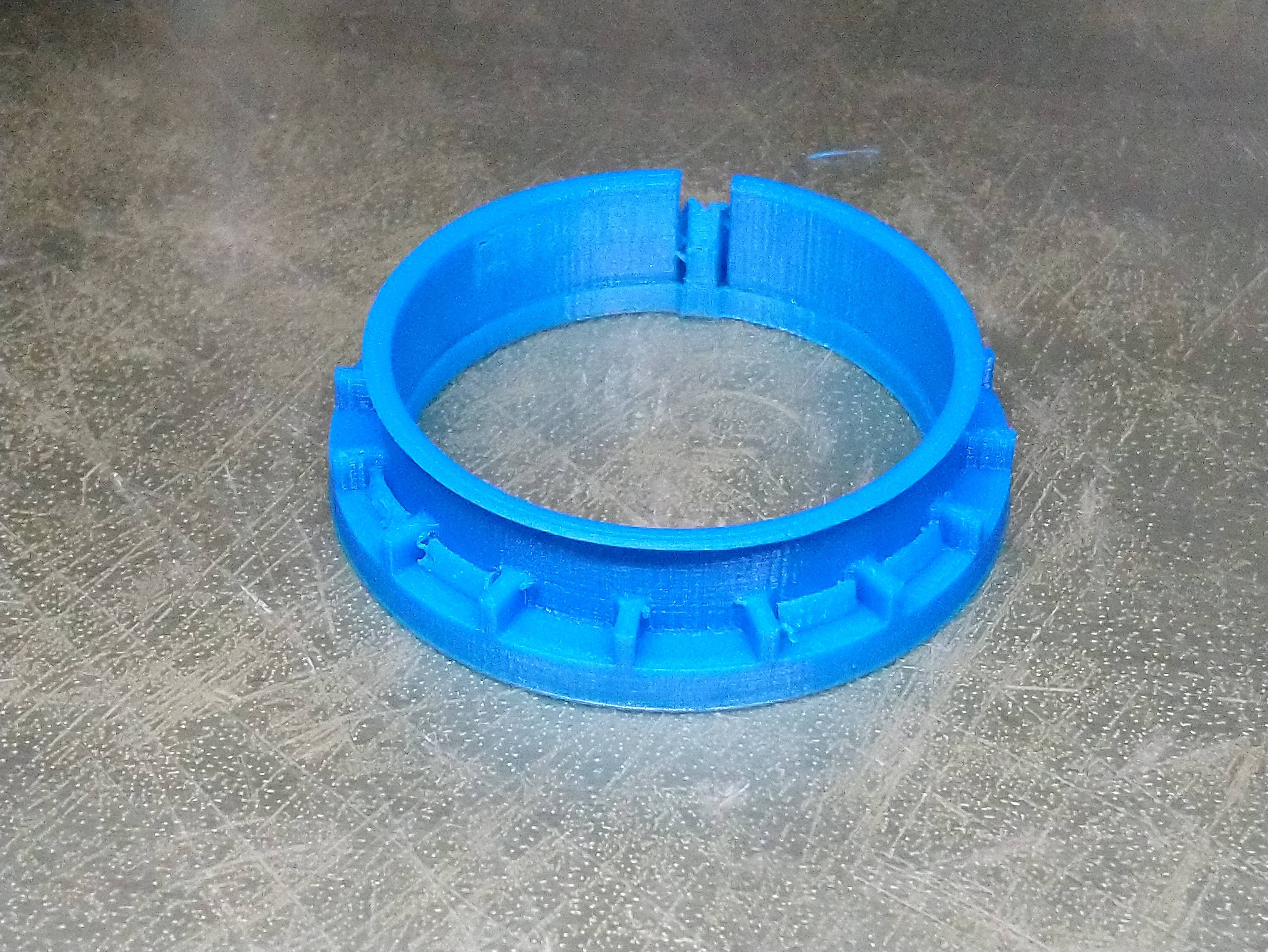
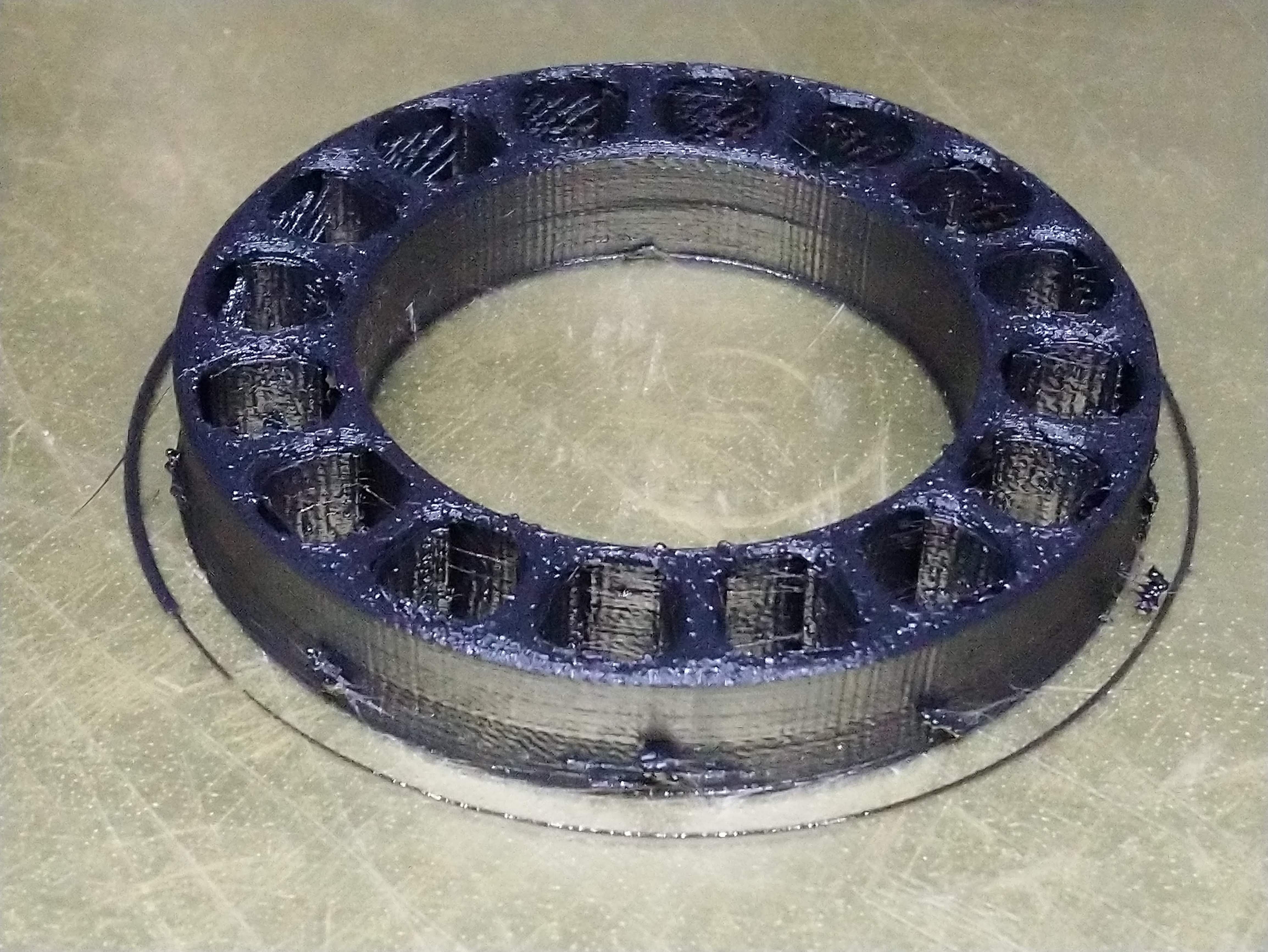
I made the LED ring cover with flexible TPU/TPE/Ninjaflex filament . This allows me to have the cover flex to get around the ring and have some indents to lock the board and bezel in.
Printed the bezel in "natural" PLA filament. It turned out that all of the soldered vias on my homebrew 16 LED ring were pushing it up, so I ended up printing it again. That one also didn't fit, so I ended up going at it with nippers until it kinda fit.
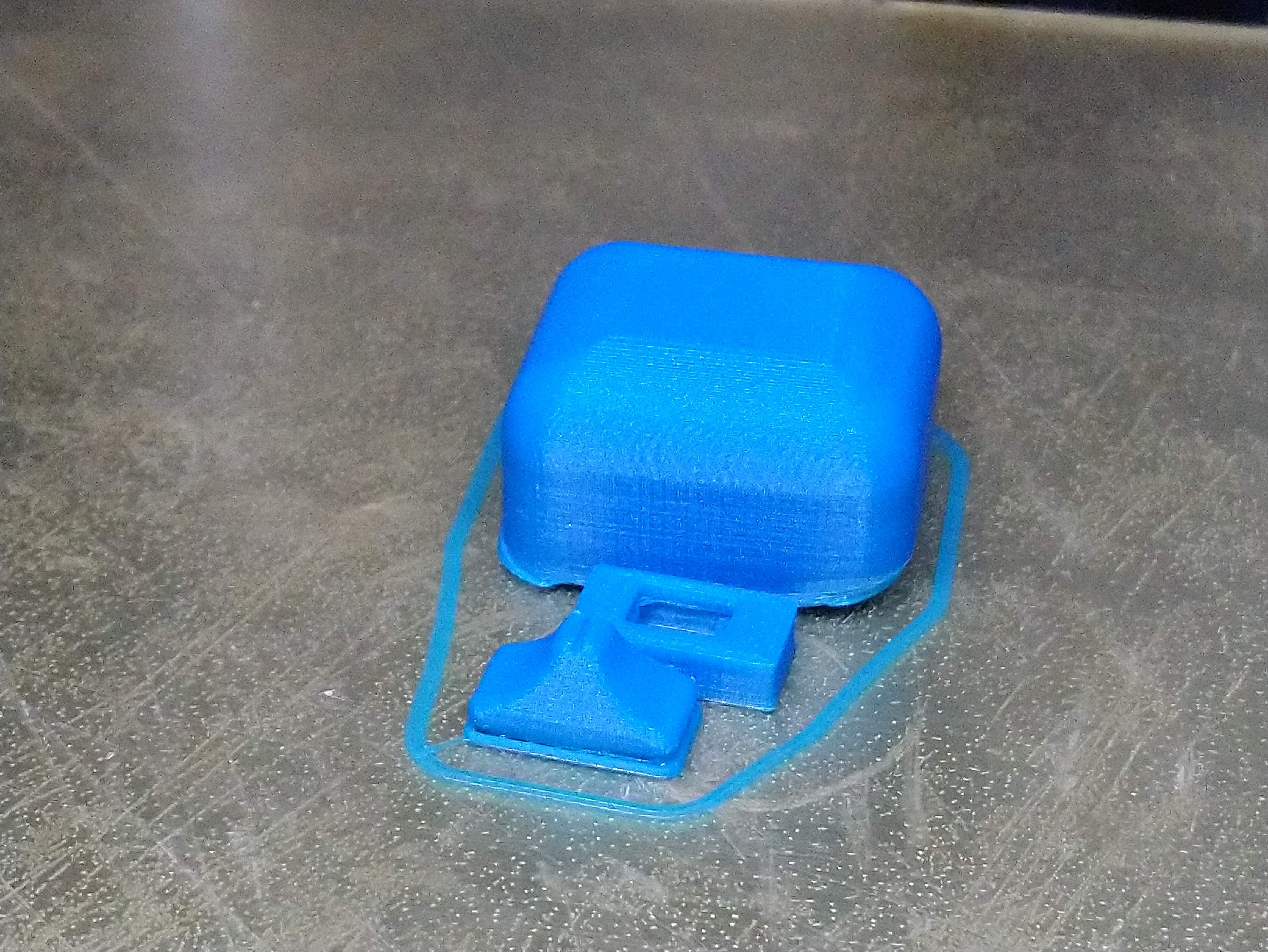
I also needed a cover for the amplifier board.
So I designed that.
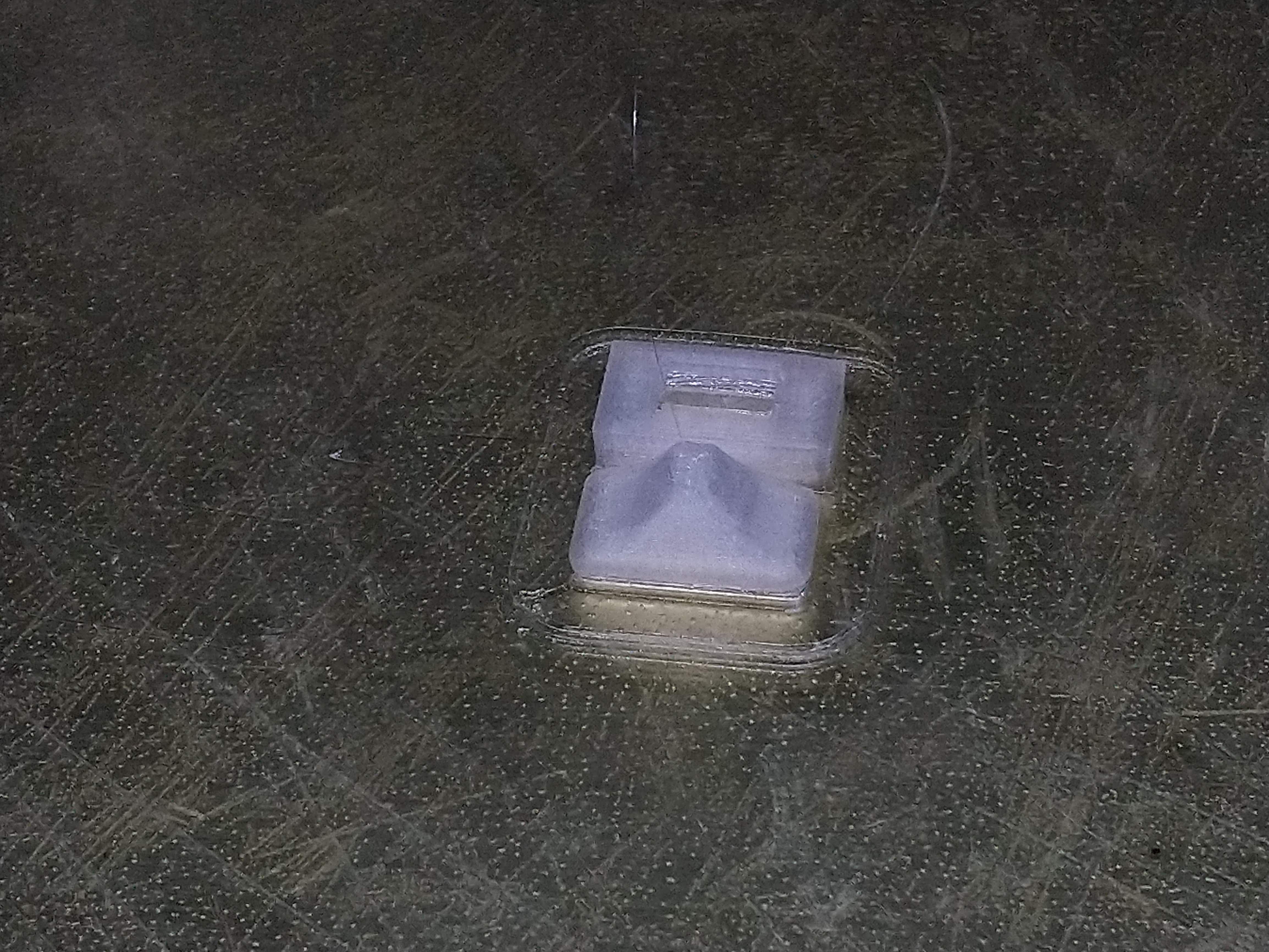
I also needed to make an end for the switch and a plug for the hole in the case for the switch that is too big.
Hey, look here is a thing! This makes it sound like I didn't spend my entire working day on this. Rest assured that I'm STILL working on it.
Those colors sucked, so I reprinted in colors that match the existing case.
For some reason, the blue is less snug than the natural, so I had to use the natural white version of the switch.
But hey, I promised you a belt mount. Well, It kinda takes awhile to print, so you'll have to wait, but here is a cool render.
While I slog through boring bits like writing code and cleaning up the PCB design, it was nice to discover that the project got another accolade in the Hackaday Prize contest: the "Diva Plavalaguna" Achievement: You've built a musical item so unexpected it blows everyone's mind."
a USB port (USB B, because I hate all of the smaller USB jacks).
a headphone jack.
a new power switch that switches both power and ground, batteries properly in series.
diodes to allow batteries and USB to be attached at the same time and let the unit be powered by USB.
a fix for the lack of pins for the MODE button.
capacitors on all of the WS2812B RGB LEDs.
Whew!
Here is a lovely 3d render. Note that it shows all thru-hole components mounted in most places, but rest assured that I actually have an option for surface mount parts for manufacturing. The thru-hole parts are used in the 3d render because those are larger and the case needs to be constructed around them because they are going to be harder to fit.
Back side of the board shows the new capacitors on the LEDs, and the USB and headphone jacks.
The USB port and headphone jack are optional; they can be removed to get the price down, although saving a dime seems silly here. Note that there is a little extension on the board for the headphone jack; that is because I now know that the boarder on the case is going to be at least 7mm, and it sticks out from the PCB so that the jack won't be recessed too far inside the case. Likewise, the edge location of the USB port.
Also, the batteries have been moved as far to the left and right of the board as possible, and all of the amplifier circuitry has been moved out from behind the batteries. Mostly, this makes it possible to mount the batteries to the PCB if one is using it without a case.
Finally, all of the battery and speaker connectors have been changed to vertical pin headers to make them a little easier to fit; there were a lot of problems before with the speaker connection getting stuck under the bezel
I've also prepared a parts order for AliExpress that I have posted for approval. I hope to get that order out by tomorrow.
While I wait for parts, I'll be getting back to working on the software.
Thank you everybody who "Like'd" "Stylish: The Trucker Belt Buckle Synthesizer" !
There is still a lot of work ahead!
If anybody hasn't "Like'd" it on the Hackaday site, please do so! Besides the (remote) possibility of placing in the top 5 of the Hackaday contest, there is still the chance for $5k in the Tindie manufacturing contest which judges on the 24th!
Because Stylish is designed to be a manufacturable product, and also a kit, I think I have a much better chance at this one than many of the other entries that are meant as a one-off, or are too big for the Tindie store.
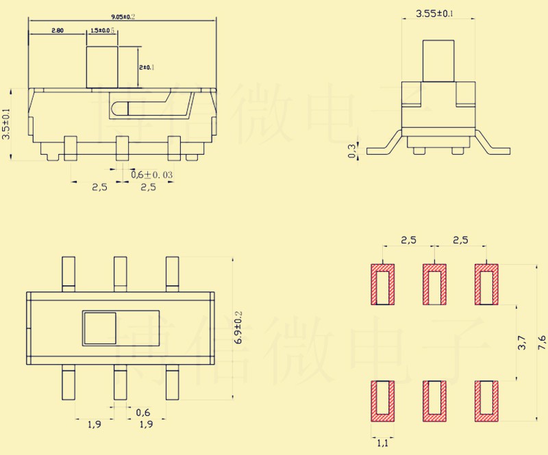
I like having 3d models for PCB parts so that my 3d board renders will be accurate. I found a lovely switch on AliExpress (which I still haven't even placed the order for) and decided that I needed a model. But the internet didn't cough one up, so I wasted a whole evening and got it done.
This was made possible by the fact that they did include a very nice drawing of the part and some decent pictures.
I could have made a simpler model.
I could have done without.
But I had to do it.
And I had to do it right.
I don't know what that says about me.
EDIT: The component is here on AliExpress. It is listed as "YT2024Y MSS22D18 MINI Miniature SMD Slide Switch 2P2T 6Pin ".
I made the 3d model available on Pinshape here, but Pinshape seems to be focused on 3d printer stuff, so they won't take STEP files, which makes it kinda useless for KiCAD. So I put it in the GitHub for the project here.
FURTHER EDIT:This switch is crappier than I thought and kinda fell apart on me.
This project is powered by AA batteries. Normal, non-rechargable AA batteries. But I'd also like to attach it to USB for stuff, and draw power from there when it is so attached.
So, the worry is that USB power will back-bias the batteries and they will eventually leak or explode. That would be irresponsible. So I should probably do something about that.
Now, the easiest option is to simply use a 3 position switch, which has one direction for battery power, and one for USB power. But that's confusing, and I'm not sure what happens when you are attached to USB but on battery power. I don't want to do stuff that blows up computers USB ports, either.
Now there are plenty of solutions that provide all sorts of protection for circuits against voltage spikes, reverse polarity, etc. Some of the protection chips alone are $2.50-$5, tho, and whole board solutions from Adafruit are $10+. This project is shooting for a $10 price point for the whole thing, so the price points on that kinda stuff aren't really reasonable! And many of those parts just can't be sourced easily in China, where the PCBA happens. If it isn't on AliExpress, I can't use it!
So, I'm looking at a bare minimum solution that adds a few pennies to the design and doesn't impede performance.
The simplest transparent option seems to be to put a diode in series with the battery and the power in, and another on the USB side.
But I'm a n00b. What kind of diode?
I really had no idea, so I got in the Hackaday.io Hack Chat and talked to Al Williams and Jez Boxall. Al pointed out some useful articles ( 1 & 2) and suggested a Shottky diode with a low VR . After some looking around, I found the 1n5822 Schottky diode on AliExpress for barely over a penny! Al had decamped by this point, but Jez seemed to think the specs were in range for this project. Second opinions are good!
I also found a lovely set of articles on the topic of polarity protection which seemed to be in the right direction for what I was doing.
I finally decided to use a diode on the positive side of batteries, and on the positive side of the USB plug to prevent backflow from batteries. Adds 2.1 cents to the design; I think they client will accept it!
Next thing to do is to order parts and wire it up!
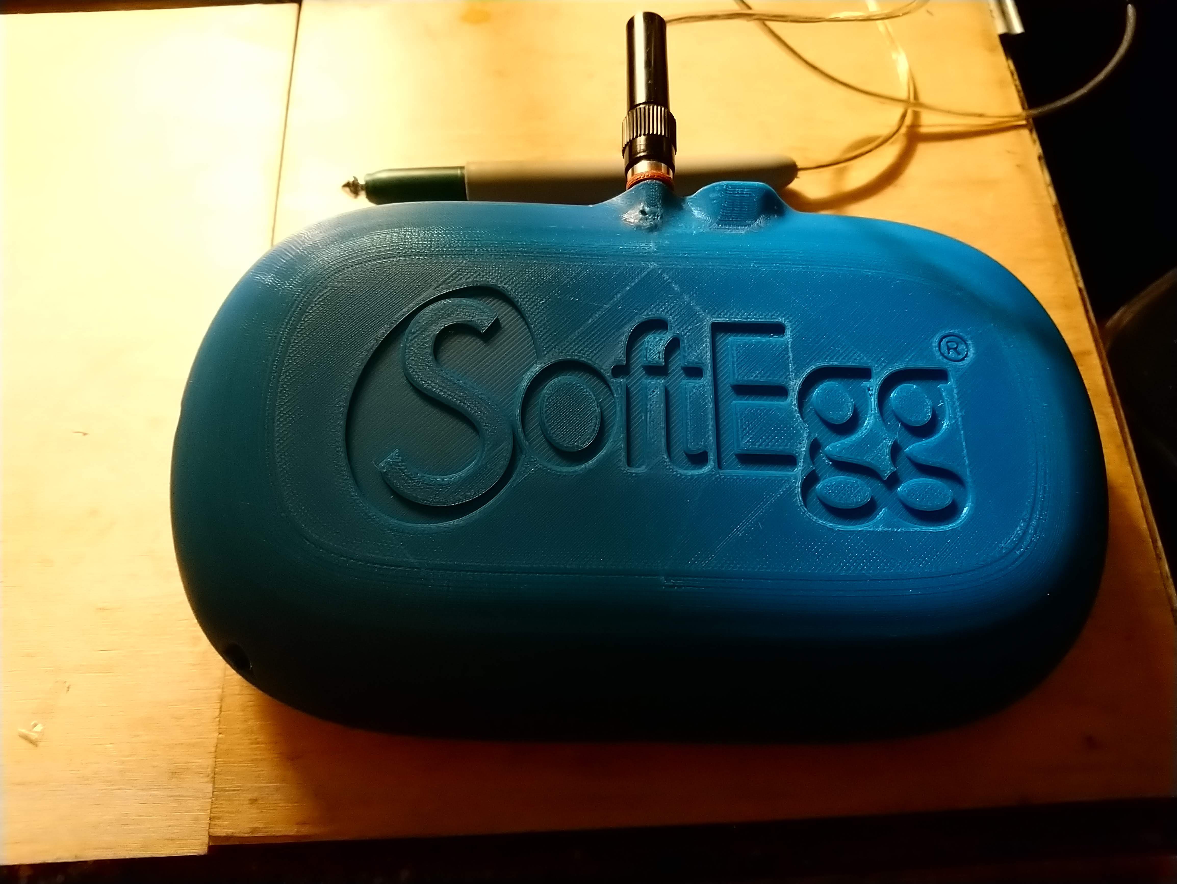
The 3d printer finally coughed up the finished print of the V2 case! It snaps together very nicely, and screws can be added for increased solidity.
From the front, it looks very similar to the V1 case, but you might notice a much larger bezel around the bottom of the keyboard, an indentation over the buttons, and the thru-hole parts for the PWM are now covered with a little bump.
The plastic under the banana plug socket had a tiny hole in it due to a very thin feature that I tried to patch with extra plastic and a soldering iron, but just ended up making it worse.
The USB port hole awaits a connector! On the real one, if this appears, it will probably be optional and perhaps differently located. Currently, you have to attach the USB cable directly to the microcontroller inside the case, which means I have to disassemble it to work on software every time. This should solve that.
The speaker mount got a redo as well, but because of some unintended relations in the model, it screwed up the rest of the model, so I had to revert all of that work. I can still get this part from the history, but having it attached to the rest of the design intent is not really possible unless I redo it.
I had also started on a bezel for the LED ring before I discovered this, so all of that work is gone as well.
I finished updating the schematic to reflect the changes I made to the board with bodge wires and cut traces, but I keep crashing KiCAD when I try to reroute the PCB to match. I've downloaded a new daily build of KiCAD, and will try to install it soon and see if it helps.
Now that the contest entry has met requirements, I'm hoping to slow down a little and get my sleep schedule (as well as various health issues) back in order, so work may be a little slower.
The whole case was mainly made for "dog-and-pony" purposes; the project wasn't really ready for that, but contest deadline was Monday, so being pretty is good. I intend to finish up the beautification with the USB port and the LED ring cover, and maybe do something about the amp board that sticks out, but after that I intend to finally get back to the code.
In the code, the state machine for the UI is being written, but because of the massive debouncing required to make this thing work, that system needs to be tweaked to accommodate the different needs of playing the piano keyboard vs touching UI buttons.
For example, when tracking the piano keyboard, if the user moves to a new key by sliding the stylus, you want to go to that immediately... unless it is a key you just left, because you might be sitting on the boundary between keys. In that case, you want to wait for it to be stable. But on the buttons, you want to wait a good long time for stability. Probably the best thing to do is to have them trigger on stylus UP, but then you think the user will be confused if they touch the thing and nothing happens. So buttons need a LONG debounce period, and states for both stylus down (update LEDs with solid color change) and stylus up (LEDs flashing in current "state color" to reflect a need for further input.)
This also applies even to synthesizer systems like the envelope generator state machine. Since the keyboard needs low latency, a "trigger" for envelope needs to start immediately on key down, but then debounce heavily any key up. This could potentially be done in the envelope generator by having "attack" reassert itself from whatever the current volume level is if there is a momentary off due to stylus motion. This works better with envelopes that are only "attack-decay" than with full ADSR tho, so this might not be an option after all.
Anyway, it's code that is in the middle of being written, but I'm in CAD land for a few more days...
 T. B. Trzepacz
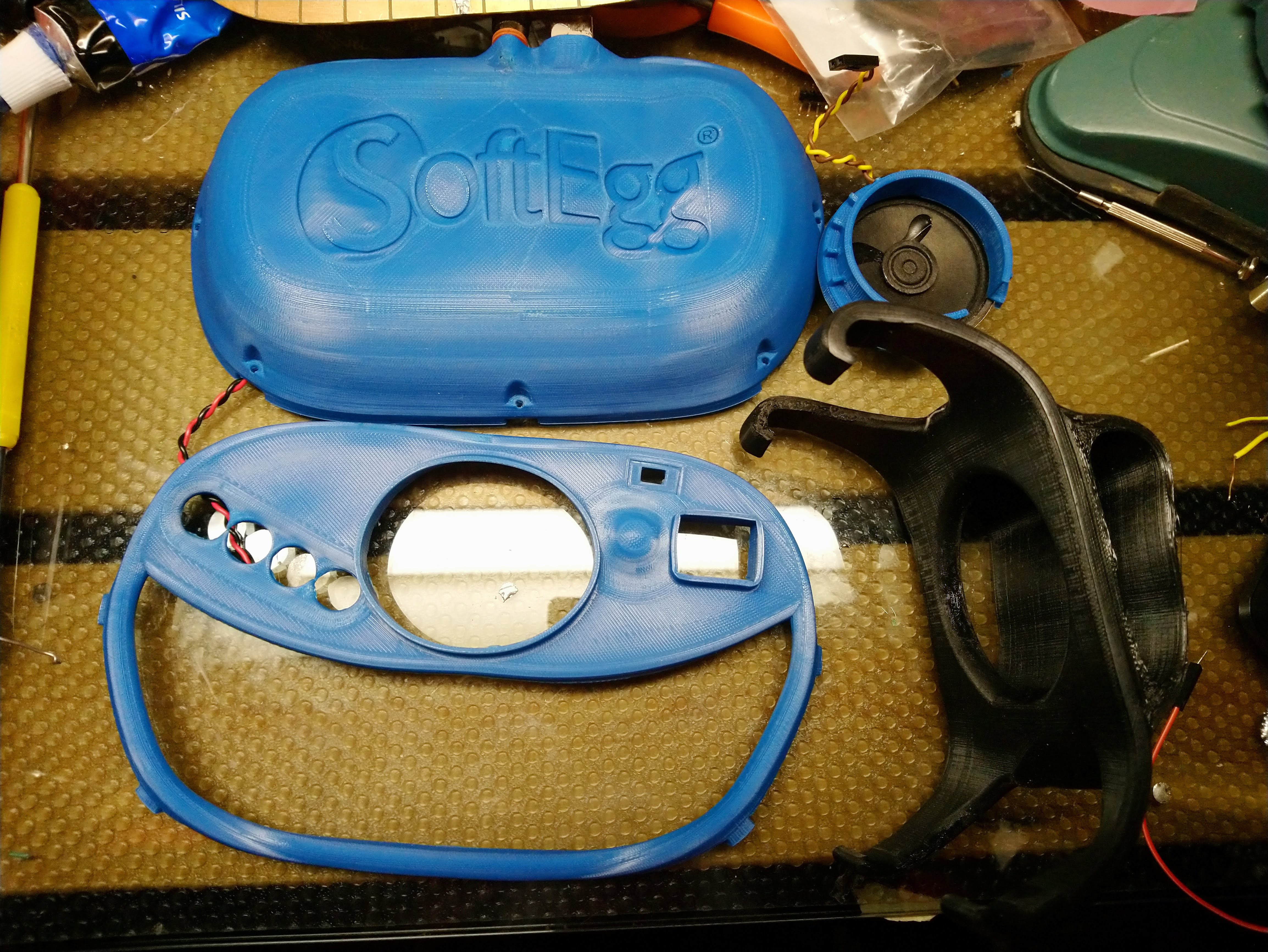

 It took some debugging, as there was one bad LED in the bunch that had to be replaced, and I had to wire one LED completely floating in the air...
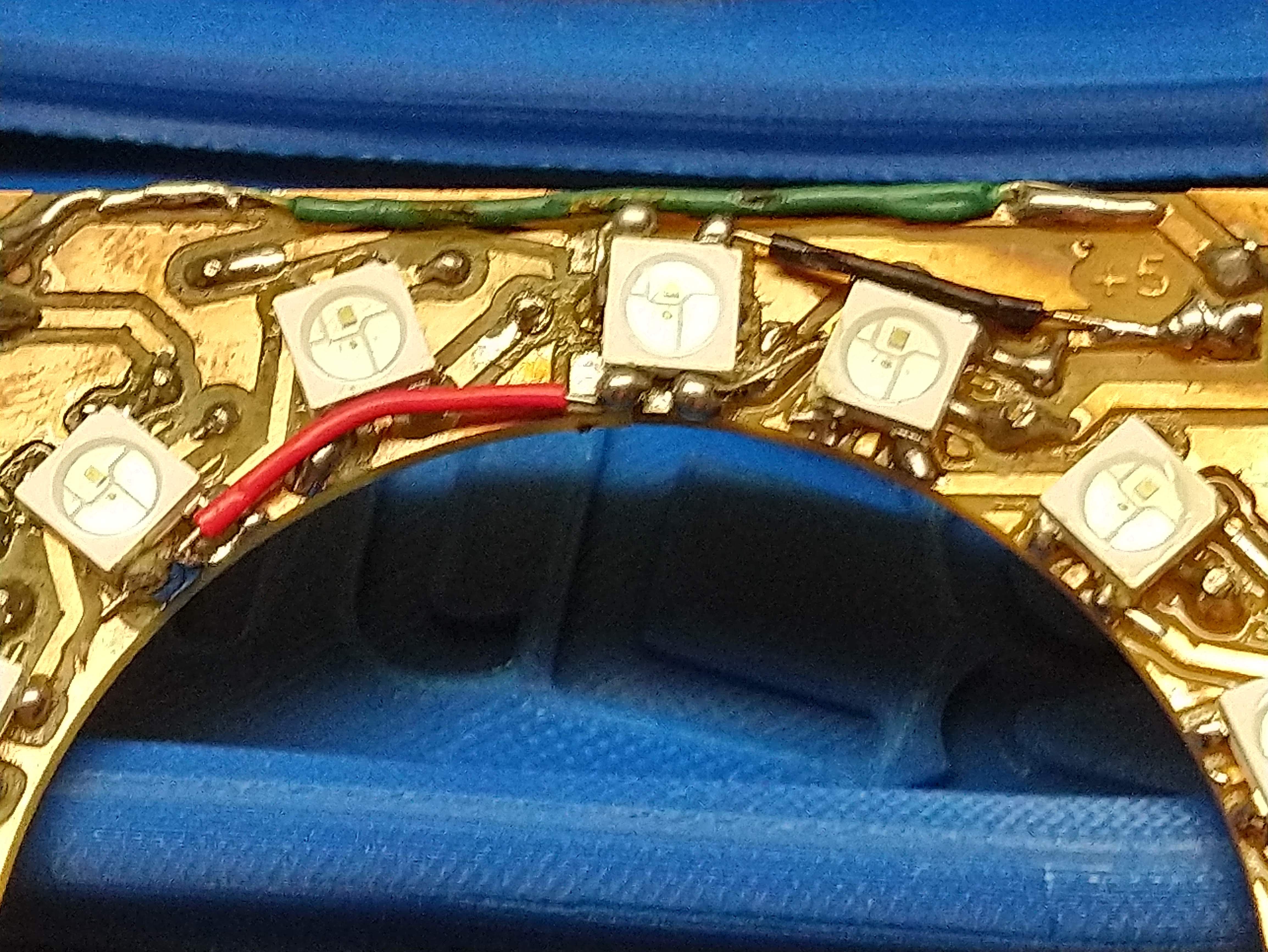

 Printed the bezel in "natural" PLA filament. It turned out that all of the soldered vias on my homebrew 16 LED ring were pushing it up, so I ended up printing it again. That one also didn't fit, so I ended up going at it with nippers until it kinda fit.
 I also needed to make an end for the switch and a plug for the hole in the case for the switch that is too big.