-
Blackbird 2 CAD Sketching
09/27/2019 at 09:16 • 8 commentsWith the end of the year coming around, we thought it would be fitting to share some CAD outlines for a new blackbird model. While we haven't officially started working on Blackbird 2, we wanted to show some very very very rough outlines for the future designs being considered. Blackbird 1 was nice because we really put a focus on 3D printed parts, modularity, and commercial off the shelf (COTS) products.
![]()
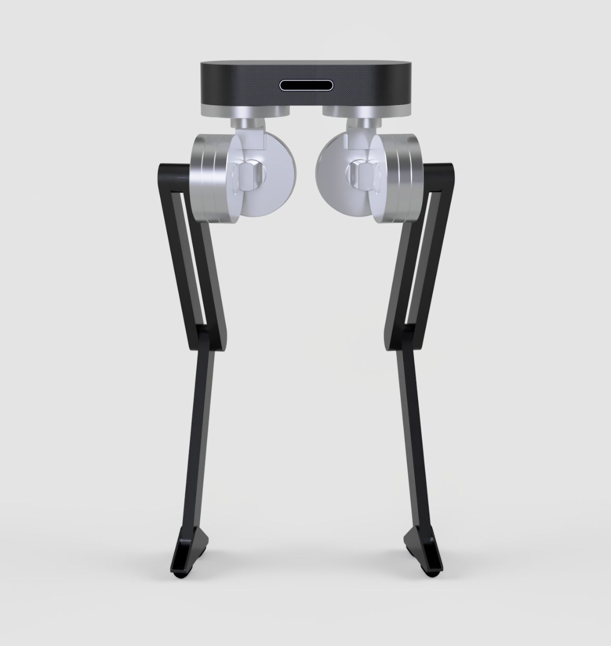
Blackbird 2 will be a far more customized solution, pursuing a more "Design for Manufacurability." It will be composed of easily accessible and manufacturable materials such as molded plastics, carbon fiber, and aluminum. We are also currently working on an entirely custom backdrivable pancake motor solution that will be used for extremely high torque and repeatability (which will outperform OpenTorque in almost every way for a small price increase). These new motors will be the bread and butter of the new design, allowing it to do highly dynamic maneuvers like jumping. Since control is the heart and soul for locomotion, the new design will focus more on lowering the leg inertia and moving the center of mass to a more controllable position.
The open hip design (above) is probably our leading design at the current moment due to it's flexibility and high degree of freedom. By keeping an open design, each leg has an insane ab/ad range and can yaw full 360 if desired. The design stacks all three of it's leg motors (hip, knee, and foot) on the hip of the robot and will rely on wiring/belts to transmit torque to the appropriate joints. This reduces the inertia of the leg and allows for better leg trajectory tracking. Some downsides of the design is the location of the center of mass, which will be higher from the ground because the legs are mounted underneath. Depending on the strength and weight of the legs, the simple block of support above the motors may not be enough to prevent the body from twisting/bending.
A second closed hip design was inspired by the design of Atlas, by Boston Dynamics. It's essentially the same things as the open hip design, except with a fully enclosed body to help support the motors. Center of mass will be lower, since the battery could be mounted lower on the body, which is better for balance. The hips are mounted off-axis from the yaw joint, which gives the foot an arched trajectory while yawing. This, may be an advantage because it could contribute to the stride phase while walking and accelerate the body faster. Ab/ad is smaller compared to the open hip design, and can only reach to roughly +-60 degrees before making contact with the body. The thought was that we could also integrate small motors into the foot to handle its smaller loads. If the integrated motor design doesn't work out, the motor can get stacked at the hip and transferred to the foot in a similar fashion to the open hip design.
The next major design steps is going to be refining the transmission system in the legs and conducting FEA analysis on the joints/body. Since there may be some material and linkage based non-linearities in the Free Body Diagrams, a fair bit of the analysis will come down to physical testing.
-
A New Optimal Controller
09/22/2019 at 05:47 • 2 commentsWhat's better than one way to control a biped? That's right, two ways to control it... and a longish log post to summarize the top level of the new one.
We've recently created an optimal Model Predictive Controller (MPC) that can also be used to control Blackbird. Now the robot can walk compliantly using SLIP dynamics or Floating body dynamics. These two options have led us to some interesting results and while I can't compare them at the moment, I wanted to show off the new controller we developed. This log will cover the super high level concepts of the control system. That all being said, what did we do, why did we do it, and how did we do it? Here are some of the basic sim result videos, but we are holding off on showing the walking of the physical robot with this controller for right now. There are still some little kinks to work out.
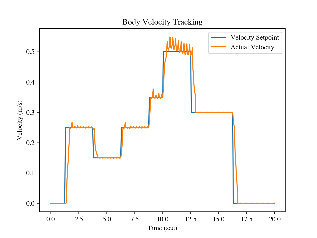
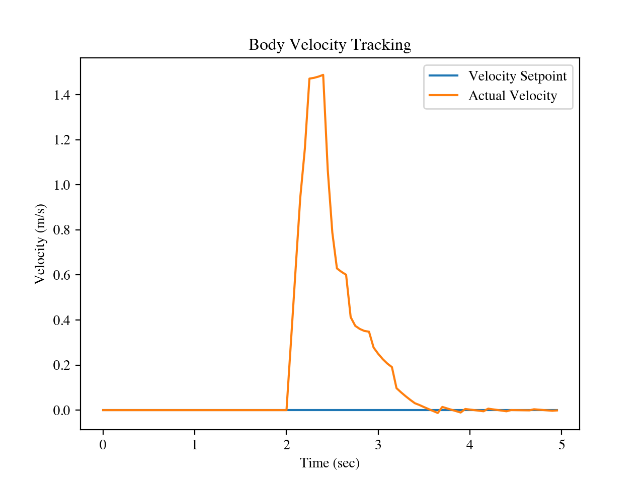
We did some disturbance testing and basic walking tests in order to verify that the controller works well. You can watch the video at the top of the log to see what they looked like visually. Basic walking testing was done to make sure the controller worked at reasonable speeds (Fig 1), The second major test we did was exerting a 100N force on the robot from the front to make sure it would keep it's balance (Fig 2). You can see that the robot is able to recover after about 1 meter of travel, but does not fall over.
![]()
Fig 1. Body following a desired speed.
![]()
Fig. 2 Response to a force at the body.
One of the main inspirations that brought this project into being was the phenomenal work by Jonathan Hurst, Christian Hubicki, and Mikhail Jones on the CASSIE and ATRIAS robots. They helped pioneer modern compliant locomotion using reduced SLIP models for bipeds to mimic human dynamics. Offshoots of this research has led to some interesting results using hybrid and optimal solutions from Michigan Robotics and AMBER Lab in Caltech respectively.
On the other side of the spectrum you have incredibly dynamic multi-legged robots such as MIT Cheetah 3/Mini (Songbae Kim, Ben Katz, Gerardo Beldt, and Jared Di Carlo) or ETH Zurich's ANYmal (by ANYbotics). We've also had some long chats with the folks over at Boston Dynamics and how they use Model Predictive Control for both Atlas and SpotMini. Who have been bringing on new formulations for simple and effective multi-layered Model Predictive Control with computed torque control.
So first of all. What is Model Predictive Control? For those that don't know (I wouldn't be surprised because this is College Graduate Level Math), MPC is a form of Optimal Control, where you basically tie an optimizer to a robust closed loop control system to determine your outputs. We love it because it can control your plant (robot) really really well if you can characterize it's dynamics properly.
![Image result for model predictive control]()
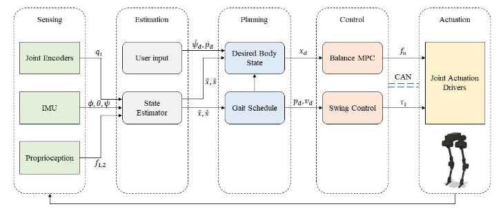
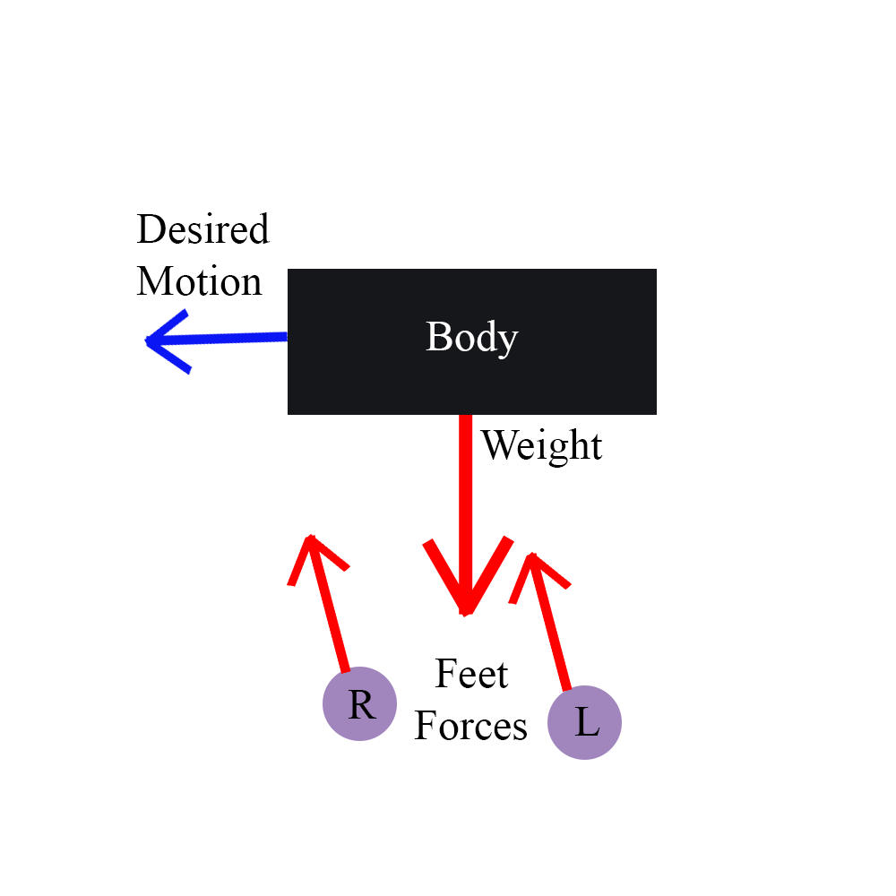
We pose the dynamics of the robot in two stages. The body of the robot just acts as a floating mass a distance from the ground. The MPC is only responsible for optimizing the motion of the state of the body mass in space based on the force each foot exerts on the ground. Basically the mathematical model boils down this: the feet are at a specific place based on the walking gait and have to exert a force that keeps the body balanced (counteracting all that inertial force from the body) and moving based on the desired body trajectory. Based on the desired forces that the optimizer determines the feet have to exert, you can do the Jacobian math to transform the foot force into leg joint torques. Note that this prediction only works if your leg's are light and have little inertia, because we just abstract them away to simplify the model.
![]()
The second layer of the robot is the leg swing dynamics. Hooray for more force control!!! The MPC is only used when the legs are on the ground. When the legs are in swing, we predict the leg dynamics (feedforward control PID control) using inverse dynamics in operational space to determine the torque each joint has to exert based on the desired position, velocity, and acceleration of the leg.
[source]
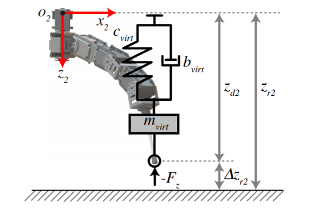
Now here is the cool part about leg dynamics. When you have relatively high bandwidth actuators (like Series Elastic Actuators [Gil Pratt] or Quasi Direct Drives [Songbae Kim/Kalouche]) you can do something called Impedence Control. Impedence Control (virtual spring control) is basically where you set all your PID gains for exerting a force based on an imaginary spring/damper. This allows the legs to act compliantly exactly like a spring to dampen the impact of the foot when it makes contact! Take the basic spring equation, F=kx, and basically make your Kp=k and your basic damper equation, F=cv, and make your Kd=c, then let run your control algorithm super super fast (we run ours at 1kHz).
That's it for the control! Two layers. Optimal (MPC) for balancing and impedance control for foot trajectory tracking and impact mitigation. Then you tie those two heavy math models with all your gait dynamics and ta-da you got yourself a well controlled walking robot.
-
Testing the trajectory tracking of the legs
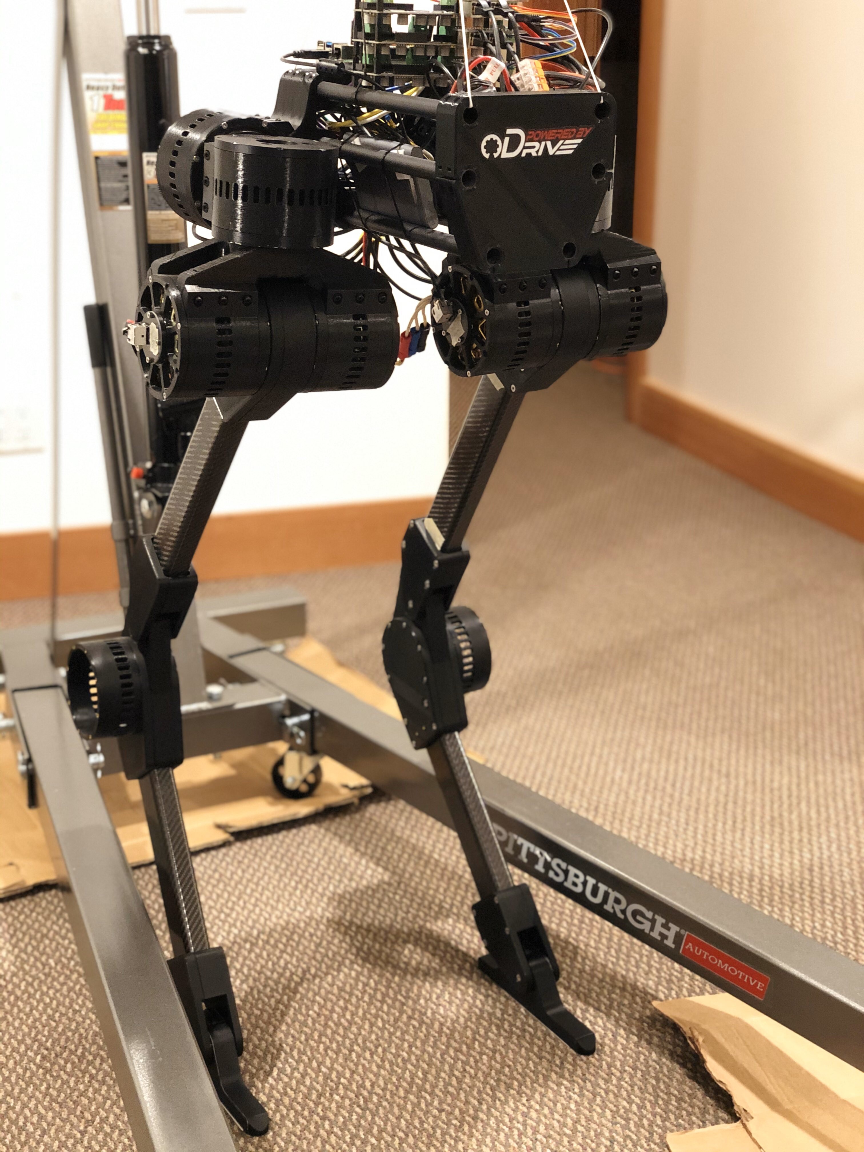
09/22/2019 at 04:05 • 0 commentsIt has been a few months since there has been an update for this page. Over the last few months there has been a ton of work finalizing the physical robot and improving the overall control code. Now that everything is all wired up on the robot, we can start looking at the tracking performance of the legs during the swing phase of walking. We looked around at a few different methods for generating trajectories. You get a preview of it walking in the air while we were testing the trajectories.
We decided to just settle with a stable polynomial spline trajectory. There are many types of splines out there, such as cubic, quintic, clothoids, etc., but a simple cubic spline was the best fit because we wanted basic acceleration motion profiling for the inverse kinematics and dynamics of the leg. Below is an example of a a basic cubic spline interpolating a few data points (This is not that actual trajectory of the foot, just an example).
![figure_1.png]() For those that don't know cubic splines (red) have pretty bad position tracking if the distances between knots (X's). Our trajectories are getting calculated online based on the swing distance needed to walk at the desired speed, so cubic spline inaccuracies shouldn't be an issue because we can generate plenty of knots to interpolate during the swing trajectory.
For those that don't know cubic splines (red) have pretty bad position tracking if the distances between knots (X's). Our trajectories are getting calculated online based on the swing distance needed to walk at the desired speed, so cubic spline inaccuracies shouldn't be an issue because we can generate plenty of knots to interpolate during the swing trajectory. Since the robot also has a concept of force control, the trajectory only acts as soft guideline for the feet. If an object interferes with the foot before expected, the proprioception from the QDD's will notice and allow the robot to preemptively finish it's trajectory and act compliantly with the object disturbing it.
-
Mechanical build
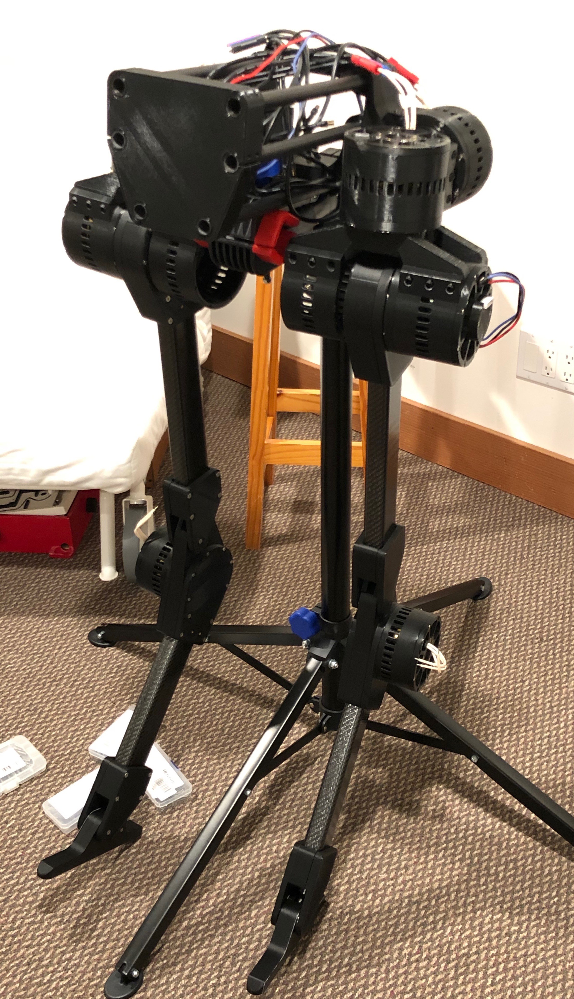
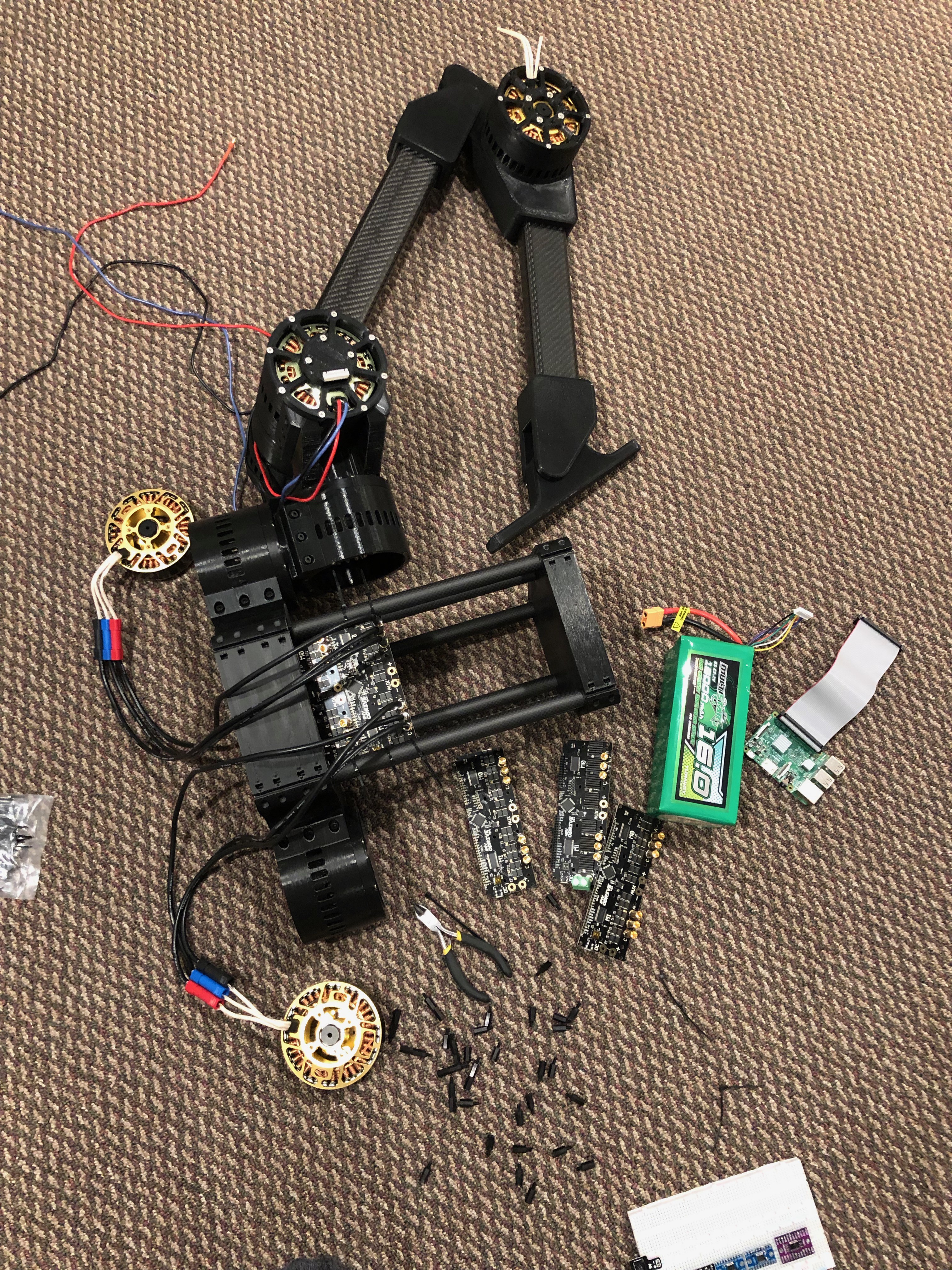
04/30/2019 at 06:10 • 0 commentsOver the last few weeks, I've been iterating on the design and making parts. The Blackbird is now close to being ready to walk.
The few remaining challenges to be solved have to do with the electronics, mainly wiring up the Raspberry Pi and synchronizing all the motors over CAN bus. I've chosen to use five MCP2515 CAN boards connected to the Raspberry Pi over SPI. Each of the five CAN channels will connect to a single ODrive board, ensuring the 1000 Hz control frequency required for closed-loop torque control.
Special thanks to ODrive Robotics for sponsoring this project.
More updates coming once it walks (hopefully within the next couple weeks!)
![]()
![]()
-
More controller improvements
01/04/2019 at 07:06 • 0 commentsThe Blackbird has a couple new tricks. It can now turn around and walk over stairs.
I still have more features to add (for example, the ability to stand still), but once that's done I'll publish the source code for the controller.
-
Balance Control
12/17/2018 at 23:55 • 0 commentsI've implemented PD balancing control for the torso. Previously there were prismatic constraints keeping the torso parallel to the ground, but now the robot is entirely self-balancing.
To prevent the feet from slipping, the controller limits the balancing torque according to the current axial force on the leg. When the axial leg force is small (such as immediately after touchdown or right before liftoff), the controller knows not to apply too much balancing torque to that leg.
Conversely, during the double support phase (both legs on the ground), the controller evenly distributes the balancing torque between both legs. This keeps it from simultaneously applying full balancing torque to both legs, which would cause the robot to "overbalance" and fall over.
-
Walking control part 3
12/07/2018 at 05:07 • 0 commentsI've added the full-order Blackbird model to the PyBullet simulation.
It's running the same SLIP controller as before, but the Blackbird's torso and feet are constrained to the positions of the SLIP walker's torso and feet.
This means the assumptions of the SLIP model are no longer true (the legs are no longer massless), yet it performs admirably with no modifications. I believe this proves something about the inherent stability of my robot/controller design.
-
Walking control part 2
12/06/2018 at 01:08 • 0 commentsHere you can see the improved controller in action. It's able to walk in 3D (in this case following a circular path) and reject large disturbances. Still to be added: torso balancing, transitions between walking/standing, and yaw control.
-
Walking Control
11/25/2018 at 04:31 • 1 commentPrior to building the robot, I'm developing the controls on a reduced-order SLIP model. The robot's legs are modeled as massless, springy linear actuators on revolute joints. All the mass is located at the hip.
The controller here was inspired by this paper.
This controller has two basic parts:
State-based control: Switches each leg between the stance and swing controllers according to whether the foot is in contact with the ground.
Time-based control: Lifts the legs and performs energy injection according to a repeating timer. The timers for the two legs are 180 degrees out of phase with one another.
The stance controller holds the leg at a constant length while allowing it to swing freely, while the swing controller rotates the leg to match the desired touchdown angle. The touchdown angle is proportional to the difference between the desired and current velocity.
Energy injection is accomplished by temporarily increasing the leg spring constant during the second half of the stance phase, thereby producing extra force in the direction of motion.
Next I'll extend the controller to work in 3D (as it's currently confined to the sagittal plane) and add balance control for the torso.
-
Leg testing
09/24/2018 at 06:43 • 0 commentsI'm running some sinusoidal trajectories on the leg to simulate different modes of locomotion such as walking and jumping. The actual controller will be far more complicated of course, but this gives me the opportunity to check the range of motion.
I also put the leg right-side-up on the ground to see how much current it draws when standing. The results were promising -- only 15A per actuator. Or in other words, only 37 watts for the entire leg. It seems highly likely that I'll be able to hit the goal of 2 hours of operation on a 500Wh battery. (The real robot will need to support more weight, like the battery and yaw/roll actuators, but this will be mitigated by the new actuator I'm designing that features a 50% higher gear ratio and better cooling.)
Blackbird Bipedal Robot
A low-cost, high-performance bipedal walking robot

 [
[ For those that don't know cubic splines (red) have pretty bad position tracking if the distances between knots (X's). Our trajectories are getting calculated online based on the swing distance needed to walk at the desired speed, so cubic spline inaccuracies shouldn't be an issue because we can generate plenty of knots to interpolate during the swing trajectory.