Thomas
-
First STM8EF application project on HaD
01/30/2017 at 10:29 • 0 commentsIn this project log I wrote several times about cheap Chinese DC/DC converters with a STM8S based voltmeter that can be converted into something much more interesting: a programmable power supply.
Yesterday I started a "HaD Downstream Project" to track the progress with this board. The new project isn't fully independent, as it will contribute requirements to this project (downstream is a bit misleading - in a development process it's actually one integration level up).
The first requirements are:
- all aspects of LED_MUX should be handled by the board support code
- assigning RAM to board support code should not not require changing forth.asm
The second requirement is trivial to solve.
I solved the second requirement with a "RAM pool" and a set of macros, and now I wonder why it took so long to do such an obvious thing. The disadvantage of automatic RAM allocation is of course that addresses now depend on the configuration (for the application there is no problem since a Forth word can export the address). For debugging a look into the list file is necessary. I guess I sub-conciously re-applied 80s embedded control practice: the RAM address sheet. Meh.
-
Bump to v2.2.6: new features, same binary size, more user code
01/28/2017 at 22:49 • 0 commentsI just released STM8EF v2.2.6 with some really nice features from the development branch:
- significantly more compact compiled user code
- interrupt code in Forth (thank Elliot for nagging me)
- simulated COM ports are no longer limited to Port D (but work with any GPIO)
- more flexible board configuration, e.g. external interrupts
There was also an important bug fix for DO LEAVE LOOP/+LOOP (LEAVE actually works now, and it's possible to use negative increments).
Thanks to new coding techniques, e.g. TRAP for literals, the binary size still is within the same bounds as before:
- interactive Forth (the use case of the original STM8EF code) < 3800 bytes,
- CORE ("compile to Flash", interrupts in Forth) < 4096 bytes
- MINDEV (DO-LOOP, CREATE-DOES>, board I/O, background tasks) < 5000 bytes
- W1209 (7S-LED display, COM-simulation, board keys) < 5500 bytes
The code generator improvements (relative calls, STM8 opcodes for literals, branch and exit) reduce the size of compiled user code by 20-25%. This should be sufficient for 5 to 10 screens of Forth, enough for non-trivial applications.
Edit: with this release some of my personal goals were reached, and it's some kind of milestone. I took the opportunity to update the project's description and details. Sorry for the update spam :-)
-
Coding Interrupt Handlers in Forth
01/26/2017 at 21:29 • 0 comments@Elliot Williams convinced me that writing interrupt handlers in Forth instead of assembly (or C) is a Cool Thing. I had pondered a lot about how to do that with the least amount of overhead but it took a lengthy discussion with Elliot to get it right!
There was a problem to solve: the STM8 register X is the Data Stack pointer, and it's also needed for implementing certain core words. The assumption that "X is TOS" isn't always justified. There is no way around this, except by blocking interrupts, or by rewriting code so that X always represents a valid stack pointer (with undesired effects like increased code size or longer runtime).
My "the most simple thing that works" solution assigns a small clean data stack to user-defined interrupts. The data stack is just 8 cells deep, but that should be more than sufficient (please read below why).
Interrupt handlers in Forth code are now based on the following words:
- SAVEC to save the context
- IRET to restore the context and return from the interrupt
- IVEC! to set an interrupt vector
Writing an interrupt handler is easy - here is an AWU (Auto Wake Up) handler as an example:
: IVEC! ( a n - -   ) 2* 2* $800A + ! ;
nvm
: HALT ( -- ) [ $8E C, ] ;
: awuint SAVEC awu_csr1 c@ IRET ;
: initawu 38 awu_apr c! 1 awu_tbr c! 16 awu_csr1 c! ;
' awuint 1 IVEC!
ram
The interrupt handler awuint first does a Forth VM context switch with SAVEC. Reading awu_csr1 clears the AWU interrupt flag, and IRET restores the Forth VM context and returns to the interrupted code with IRET. It's not necessary to leave the stack balanced (otherwise DROP would be required). The word IVEC! stores the address of our new hander to interrupt vector 1 (the AWU interrupt in Flash memory). Since IVEC! is only needed at "compile time" it can be compiled to RAM and doesn't need to be part of the Forth image.
The word HALT encodes the STM8 HALT instruction that shuts down the CPU clock until an interrupt occurs (I first added a word HALT to the Forth core but this user code implementation is just as good). When I run HALT with this code, it returns because of the Auto Wake Up interrupt. Note that I didn't find the time to make sense of the AWU configuration, and I simply took the AWU timing values from this page.
When writing interrupt handlers in Forth, I would like to recommend the following practice:
- interrupts should only be used for low-level code, e.g. for using µC peripherals that require interrupts to work
- be careful about data- and return stack use - 5 levels deep should be plenty!
- the code should be fast - if in doubt use pin-debugging with a scope or a simple logic analyzer for testing the timing
- only do the data processing that's absolutely required for meeting your application's timing constraints. The rest should be done in a low-priority task (e.g. background)
- simplicity is important: don't use any fancy high-level words (e.g, output string formatting shouldn't be used)
- one should be carefully assess potential side effects of character I/O (if required!)
- in many cases you'll need the µC manual to understand what your code is doing, and fancy abstractions won't make your code more readable
Working code with SAVEC and IRET is in the develop branch on GitHub. I'm still working on some details but it will be part of the next release.
-
More fun!
01/26/2017 at 06:39 • 0 commentsYou may have noticed that this project page isn't one-way communication any longer!
Several people *) now contribute to the progress in the following ways:
- by writing their own application code and challenging limitations
- by contributing with requirements, and discussing implementations
- testing and filing bug reports
- writing new board support code, or proposing new boards
- interest for, and encouragement of, all of the above
Thanks guys, you're making all this more fun! I hope to see a related project, soon :-)
*) hat tip to @Elliot Williams, @ajlitt, and others
-
STM8EF v2.2.6.Snapshot: embarrassing hotfix (and new features)
01/22/2017 at 17:45 • 0 commentsA long time ago, I proudly released the "DO .. LEAVE .. LOOP" feature. I should better have spent more time testing, and less time announcing, since LEAVE was all but working. For some reason, my test cases worked, and some change to the code base must have exposed the bug. The new (pre-) release 2.2.6.Snapshot with the bug fix (and some more features) is here.
I noticed the bug during tests of new features for code size optimization, like a DOLIT implemented with TRAP, and relative addressing of CALL (now, depending on the code, STC can now be as compact as DTC).
Release of support of new boards (like W1401 and DCDC) will have to wait a little bit longer, just like introducing the W1219, or a voltmeter with very friendly breakouts that I had in the mail last week. At least, the code in the GitHub "develop" branch contains some initial board support for the W1401 (without keys and outputs), and for the DCDC converter (the serial interface isn't fully usable yet).
-
The code densitiy TRAP
01/21/2017 at 10:32 • 0 commentsFusing code to improve code density has a high potential of making refactoring very difficult. In this project I took the freedom to fuse core code when I saw a size (sometimes also a speed) advantage, and where I didn't see possible future variation points. In some cases I un-fused code from the original STM8EF source to get desired variation points (e.g. vectored I/O). This was easy since much of the eForth source code is written in Forth, and fusing code is no problem as there are no fundamental changes to the design of eForth.
So, where is the point? It's a pun. I used the TRAP instruction to improve the code density of Forth user code :-)
Please let me explain by diving a bit into how the Forth VM, the virtual CPU that drive a Forth systems works. When Forth compiles a "word", it creates a thread of tokens for consecutive execution by the Inner Interpreter, the execution unit of the Forth VM.
The Inner Interpreter can be implemented in hardware (a Forth CPU), or in software. There are established coding techniques for general purpose CPUs, like the often used Direct Threaded Code (DTC) where tokens are pointers to the so called "Code Field Address" of words.
Tokens can represent any of the following:
- other Forth words like DUP, SWAP, or other user words, that get executed in sequence
- the DOLIT instruction to push an literal integer, following the token, to the Data Stack
- the EXIT instruction that ends a thread, to return to the calling thread, or to end execution
- the BRANCH instruction to move the instruction pointer to a different point in the same thread
- ?BRANCH, DONEXT, or DOLOOP which are similar to BRANCH but conditional (using data on the Data or Return Stack)
Words like DOLIT or ?BRANCHdiffer from ordinary Forth words in that they manipulate the Inner Interpreter, and don't just work with the stacks of the Forth VM, and therefor the implementation of this class of words dependents on the coding technique used for implementing the Forth VM. Only a small number of such words is necessary, and most of them are core words.
STM8EF uses Subroutine Threaded Code (STC). Here, the Inner Interpreter is implemented by the CALL instruction of the CPU, the instruction pointer is the program counter, and the CPU's return stack is used as the Return Stack of the Forth VM. Words that need to manipulate the instruction pointer, like DOLIT, do this by changing the CPU's PC value on the return stack (the one that the CALL pushes for use by RET).
The advantage of STC is speed and simplicity of implementation. Context switching for multi-tasking is also easy to achieve (I took advantage of this). The disadvantage is code size: compared to DTC a simple STC implementation needs at least one more byte for representing a token, the CALL instruction. And this is before we even use words like DOLIT and EXIT to make the Inner Interpreter change the sequence of execution.
Since we're using the CPU as the Inner Interpreter there are other some more analogies between the CPU and the Forth VM that we can exploit for optimization:
Token Optimization measure for increasing code density Trade-Off Done any Many CPUs have CALL instruction that uses some form of relative or segmented addressing for improving code density, and an optimizing compiler can take advantage. The STM8S CALLR instruction is used if the call distance is less than 128 bytes (2 instead of 3 bytes). Some code generator complexity. ✓ EXIT EXIT can be coded as native RET (1 instead of 3 bytes) None ✓ BRANCH Branch can be coded as native JP (3 instead of 5 bytes) None ✓ ?BRANCH That's very hard since manipulation of the Data Stack is required (DONEXT and DOLOOP even manipulate data on the Forth VM Return Stack ). In Machine Forth, Chuck Moore changed the rules of the game to make this easier. Be like Chuck Moore.
DOLIT
Same as ?BRANCH, except what DOLIT does is a simple operation of the Forth VM.
hmmm
Edit: I worked a bit on replacing CALL by CALLR to make one more check mark in the "Done" column in the first table. I'll be playing with the code before releasing it.
In most cases, manipulating the Forth VM stacks with native code requires many CPU instructions. This also sets limits for hand-optimizing core assembly code.
If we only had more of such 1:1 matches of Forth VM instructions to CPU opcodes (like EXIT-RET and BRANCH-JP). I'm not like Chuck Moore (and I don't change easily) but ... the STM8S has one malleable instruction: TRAP.
TRAP is a "non-maskable software interrupt with highest priority". The purpose of such an instruction is to consistently manipulate the state of the CPU, e.g. in an RTOS: it interrupts the CPU's flow of execution, saves the context to the stack, runs the TRAP handler code, restores the context, and returns to where it left off. It can only be interrupted by RESET or by TRAP (which rarely ever makes sense).
I used TRAP to implement the DOLIT instruction: "CALL DOLIT MSB LSB" can now be coded as "TRAP MSB LSB", that's 3 bytes instead of 5 for representing literals!
Here is the code (you may need the page on the TRAP instruction in the STM8S programming manual to make sense of it):
;       TRAP handler implementing DOLIT
;       Push the inline literal following the TRAP instruction
_TRAP_Handler:
        DECW    X
        DECW    X
        LDW     (3,SP),X               ; XH,XL
        EXGW    X,Y
        LDW     X,(8,SP)               ; PC MSB/LSB
        LDW     X,(X)
        LDW     (Y),X
        LDW     (5,SP),X               ; YH,YL
        LDW     X,(8,SP)
        INCW    X
        INCW    X
        LDW     (8,SP),X
        IRET
In order to use it for compiled user code I only had to change the implementation of LITERAL (3 lines), and the implementation of DODOES (3 lines), and DOES> (1 line). After applying the new "DOLIT instruction" in the core code a couple of times it had paid for itself!
In applications where a lot of literals have to be used in the code (not variables or arrays but literal numbers) the new approach has a clear code size advantage.
Of course, where there is light, there also is shadow. Here is a comparison of the old and the new implementation:
CALL DOLIT DOLIT with TRAP Execution time 22 CPU cycles 50 CPU cycles Interrupt latency 4 CPU cycles (CALL or RET instruction) 50 CPU cycles w/ TRAP context switch
Bytes on return stack 22 (multi tasking + interrupt) 9 (non interruptible) At 16MHz clock frequency, 50 CPU cycles translate to just about 3µs execution time. In most applications, the additional 2µs won't be noticeable. Since time critical code (e.g. interrupt driven video signal generation) might see an impact (even if it's coded in assembly, or C). I'll try to make this new feature optional. The result of the stack analysis came as a surprise since I already had planned for increasing the return stack headroom.
-
Getting shared GPIO serial right, and other nuts to crack
01/19/2017 at 06:51 • 0 commentsIf you're following this little project you may have noticed that I take pride in adjusting the code for supporting almost any type of cheap STM8S Value Line device.
Here is a number of constraints:
- in most cases UART pins are not broken out
- in some cases UART pins are used for communication
- in most cases there is no accessible "unused" GPIO
- in some cases there is no ICP connector, PD1 is used, and NRST isn't accessible
I did the following to meet constraints 1. and 2.:
- there is a simple "half-duplex" single GPIO configuration for the console
- the serial line simulation for interactive console can be configured for any GPIO (assumption: port change interrupt requirements of other GPIOs on the used port can be met with "falling-edge")
- two instances of serial com "devices" can be used in Forth code, one for the application, one for the console
However, I'm still working on some edge cases constraint 3:
- Sharing a GPIO for the console with the application requires priority for communication (e.g. the DP segment of an 7S-LED doesn't work while the console is being used)
- the "interactive" state has to be detected, stored, and maintained for a convenient period of time
I'm working on a solution that doesn't lead to much entanglement between communication and board support code. I'd like to restrict it to cases where the "background task" option is enabled.
Constraint 4 is a bit more complicated to meet as I learned yesterday:
- When the NRST pin is not accessible PD1/SWIM must be in input mode at least for some time
I've got it working in cases where PD1/SWIM is used for digits or segments of the 7S/LED display even if it's not used for the serial communication code (where the constraint is implicitly met).
Anther thing I've been working on is the code density of Forth user code: having literals (constants, addresses) in STC (subroutine threaded code) is quite expensive: a call to DOLIT followed by a 16 bit constant, that's 5 bytes. In the core code I got that down to 4, 3, 2, or even 1 bytes in many cases (CALLR DOLIT for 16 bit, CALLR DOLITC for 8bit constants, and LDW Y,#W and LD A,#C, or CLRW Y and CLR A with TOS in a register). This method contributes to quite some binary size reduction in the core, but it can't be used easily in user code (one work around is to use words like "0" for frequently used constants).
I now experimented with the STM8 TRAP instruction to build a native DOLIT which is just TRAP MSB LSB. It works nicely, but it takes 3 µs to execute. An 80's programmer would have been happy with that, but today it's a "size over speed" decision.
-
News on "LM2596 with voltmeter"
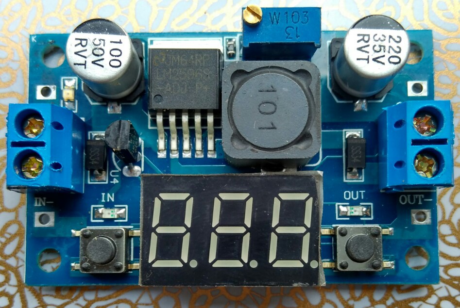
01/15/2017 at 13:17 • 4 commentsYesterday I had another specimen of the prolific cheap LM2596 based "buck converter with voltmeter" in the mail, and it's actually worth writing about!
![]()
The first obvious thing, already visible on the vendor's pictures, is that the 7S-LED display nicely covers the voltmeter part including all the passive components.
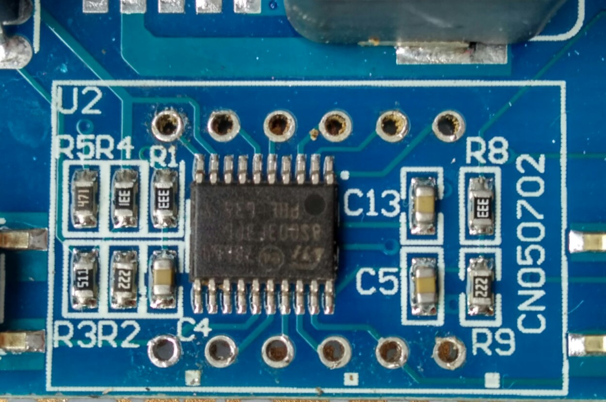
Underneath the LED display we find this nice arrangement:
![]()
The LM317 in TO92 package is directly connected to the voltage divider R4/R3 (the LM317 lacks the recommended capacitor Cout, Cin is shared with the LM2596). C13 is connected to Vcap (STM8 1.8V core supply circuit). R1/R2-C4 and R8/R9-C5 are the "voltmeter inputs" (PC4 Vin, and PD3 Vout).
PC3 is connected to LED "in", and PB4 to LED "out" without current limiting resistor (the same as the 7S-LED display). Like in the first variant, the "design" relies on the limited current driving capability, and on the surprising robustness of the STM8S outputs. The LED power dissipation is limited by a 4% duty cycle (there is a risk of accelerated degradation). R5 is connected to the green power LED.
Isn't there anything else missing? Yes, a bypass capacitor for the STM8S003F3P6 - there is none!
So, if you ever had any doubt about the robustness of the STM8S: it's unfounded. It will tolerate circuit bending practices on a mass production scale ;-)
I first assumed that the GPIOs used for the 7S-LED display are the same but they're not since the STM8S003F3P6 is rotated by 90º with respect to the first variant.
Although the LEDs "in" and "out" are now connected to dedicated GPIOs, the keys are still connected to segment LED outputs (PC5/SegE and PD2/SegG), this means that the display should be blanked during a key-press. It would have been really easy to use PB5 for reading the keys but it was left unconnected.
As mentioned in my last post there is a thing I learned about the STM8 ICP interface: it will work without the NRST pin if SWIM hasn't been disabled in software or in the configuration bits. This means that one can get Forth onto it without soldering (PD1/SIM is connected to Pin4 of the LED display)! It will only work one out of three times, but that's OK for our needs, and once we have a Forth console we don't need the NRST anymore.
Now, what can we do with it this knowledge?
- for reading ADC values of any accuracy all LEDs should be switched off
- Vin is easily accessible on the backside of the PCB, and after cutting the trace it can be used for measuring anything else
- PC3 can be exposed by removing LED "in" (there is no resistor!)
- LM2596 Pin 5 "/ON-OFF" can be cut and connected to PB4 for controlling power out (even without removing LED "out")
- PB4/ can be exposed by removing LED "out"
- for controlling the LM2596 feedback loop the pot wiper can be connected to GPIO PC3
- The Vout ADC can be used for closing an output voltage (or current) control loop
Controlling a DC motor or a hydraulic valve solenoid with this variant of the "DC/DC converter with voltmeter" module appears to be very feasible.
Other applications might be:
- Precision temperature control (i.e. not switching-mode but by setting the power!)
- Low-grade lab power supply with some control features (scripting, monitoring, synchronization, maybe even fold-back current limiting)
- LED power supply with current control
- battery charging
- ..
Who said that a piece of electronics with a horrible design can't be turned into something useful? I hereby put this $1.52 gadget on "strong buy" ;-)
I don't plan to support the first variant of the board as it lacks LED GPIOs that can be easily repurposed. So, if you want to buy one, better make sure to get this second variant (not the one in the first post). On AliExpress search for "LM2596 DC 4.0-40 to 1.3-37V Adjustable Step-Down". I've seen a green and a blue variant, and both are easy to identify (LM317 as TO92, many passive components hidden under the 7S-LED display).
Edit1: some corrections on the circuit, and more details on the used GPIOs
Edit2: I've got the main parts of the board working. The GPIO initialization code in boardcore.inc is as follows:
; DCDC STM8S003F3 init GPIO ; Codes: A ... G+P - LED segments+DP, ; 1 ... 3 LED digits, ; i ... o: LEDs "in", out, ; ".": analog inputs ; u: unused MOV PA_DDR,#0b00001110 ; ----3AF- MOV PA_CR1,#0b00001110 MOV PB_DDR,#0b00010000 ; --uo---- PB4:LEDout MOV PB_CR1,#0b00010000 MOV PC_DDR,#0b11101000 ; PDE.i--- PC3:LEDin PC4:Vin PC5:E/keyIn MOV PC_CR1,#0b11101000 MOV PD_DDR,#0b01110110 ; -21B.GC- PD2:G/keyOut PD3:Vout MOV PD_CR1,#0b01110110Edit3: more corrections, some more details. I pondered how to best control the LM2596. My idea is to synchronize Timer1 with the LM2596 switching oscillator, and to use the PC3 PWM duty cycle to control the feedback loop. It can't be much worse than the B3603.
-
XH-W1401: PD1 quadruple play
01/12/2017 at 23:08 • 0 commentsWhen I first examined the cheap XH-W1401 thermostat module (6 digit 7S-LED display, 4 keys, 2 LEDs, relay, and buzzer) I quickly noticed that using the GPIO PD1/SWIM for 3 tasks (SWIM for flashing, half-duplex RX and TX) wouldn't be that easy since it already serves for SWIM and to clock the 74HC164 shift register.
Now I found a solution: the shift register clock pulse can be short with respect to a UART bit time. I tested it with a two cycle operation (125ns) which a CH340 UART chip filtered out. First tests look promising!
It's also possible to generate the clock with one cycle (64ns) and to use a very simple RC filter (e.g. 47R/10nF) to hide it even from an unfiltered UART like the interrupt driven implementation in this project.
It's further complicated by the fact that the 74HC164 is unlatched which means that any transition on the serial line alters the LED pattern of a currently displayed digit. This can be countered by refreshing the display contents in the stop bit (sometimes even a software UART has an advantage ;-) ). The GPIO will then serve 4 needs concurrently: quadruple play ;-)
It looks like the XH-W1401 has the potential to be a supported gadget (there are variants with a front panel, and at a price of about $2.60 it's still very cheap). The schematics still has some mysteries (e.g. what they did at the sensor input, and which STM8s pins are assigned to keys, relay and buzzer) but if you follow this little project ordering a W1401 now wouldn't be all too risky.
Edit1: I tested optimized assembly code for feeding the 74HC164 with 62ns pulses, and I was mildly surprised by the bit rate. Depending on instruction alignment with 32bit boundaries I get 1.75 to 2 Mbit/sec with looped code (data shift out, clock creation, counting, branching). In my youth that would have been ... fast ;-)
Edit2: the multiplexed LED display and the serial interface on the same port appear to work. For now, the display is off while a byte is being transmitted through Rx or Tx. One of the next things will be more examination of the circuit. Especially the NTC sensor input is unexpected, and a huge capacitor at NRST made me learn a new thing about ICP through SWIM: NRST isn't always neded!
-
UART for application, serial console through SWIM
01/10/2017 at 06:35 • 0 commentsWith the following configuration the latest code on GitHub has the option to use the UART for other things than a Forth console:
         HALF_DUPLEX      = 1    ; Use EMIT/?KEY in half duplex mode
         HAS_TXUART       = 1    ; No UART TXD, word TX!
         HAS_RXUART       = 1    ; No UART RXD, word ?RX
         HAS_TXSIM        = 2    ; Enable TxD via GPIO/TIM4, word TXGP!
         PDTX             = 1    ; Port D GPIO for HAS_TXDSIM
         HAS_RXSIM        = 2    ; Enable RxD via GPIO/TIM4, word ?RXGP
         PDRX             = 1    ; Port D GPIO for HAS_RXDSIM
I used a higher flag value for HAS_TXSIM and TXRXSIM to indicate that it should be used for the console. In this configuration the UART can be used with TX! and ?RX while the EMIT and ?KEY vectors point to TXP! and ?RXP. It would also have been possible to keep the simulated serial interface free by not using a higher flag value.
Here is a test to copy chars from RX to TX in the background:: bcopy ?RX IF TX! THEN ; ok ' bcopy BG ! okThis works fine but for using it to automate an ESP8266 remote serial with background code we still need buffers for RX and TX. Next up: vectored I/O for the background and some kind of buffers. An input buffer is also necessary for using some of the interpreter code in the background.
Edit1: of course, I/O in the background is already vectored, but the vectors used are fixed. The vectors can be changed at the start of the background task, and maybe I keep it that way.
Edit2: I don't want to go for a multi-tasking/multi-user system, and changing the user context therefor isn't necessary (that would be interesting for a CPU with a vast amount of resources, e.g. an entry level Cortex M0 ;-) ). However, the eForth implementation of the words parse (single out words separated by a delimiter) and find (look up words in a linked-list or dictionary) use the temporary variable tmp, which is the only thing that binds the words to a user context (along with the compiler and the interpreter). I'm now removing the words from the implementation and use temporary storage on one of the stacks instead (the return stack). That's not much nicer than the tmp variable, but it provides a cheap multi-tasking context switch.
Edit3: I was wrong - using the return stack instead of the tmp variable is much nicer (and a bit more compact, too). Now I've got to figure out how to implement buffered I/O in a multi-tasking friendly way.
eForth for cheap STM8S gadgets
Turn cheap modules from AliExpress into interactive development kits!