Thomas
-
Easy I2C with STM8 eForth
12/03/2020 at 21:42 • 0 commentsI had some fun experimenting with the STM8 I2C peripheral. Working around its quirks and designing a code efficient yet reliable and easy to use I2C driver was a challenge. In my previous log entry I mentioned improvements for mixing control structures with optimized assembler code in ISRs.
After testing some alternatives I ended up with a very simple approach:
- Device initialization and buffer definition in user code in user code
- An ISR with a simple API
- variable I2ISR as configuration "registers" for the ISR
- I2S ( c -- ) start I2C transmission sequence with device address c
- I2W ( -- ) wait for end of transmission (optional)
The ISR is now really easy to use. Here is the code for a 24C64 EEPROM:
\res MCU: STM8S103

\ Initialization code, e.g. for 100kBit
#require I2I

\ ISR based I2C "Master transmitter/receiver"
#require I2CMA

\ temporary constants for the I2C user code
I2ISR 2 + CONSTANT TCOUNT  \ char number of bytes TX
I2ISR 3 + CONSTANT RCOUNT  \ char number of bytes RX
I2ISR 4 + CONSTANT TPOINT  \ points to TX buffer, starting with CMD/ADDR
I2ISR 6 + CONSTANT RPOINT  \ points to RX buffr

80 CONSTANT SA24C64

NVM

VARIABLE EADDR
VARIABLE BUFFER 6 ALLOT

: write ( a c -- )
  \  BUFFER follows EADDR, c=0 at least writes the address
  ( c ) 2+ TCOUNT C!   \ TCOUNT, # bytes incl. EADDR
  ( a ) EADDR !        \ set EEPROM address
  EADDR TPOINT !       \ initialize transfer pointer
  SA24C64 I2S
;

: read ( a c -- )
  BUFFER RPOINT !      \ set read pointer to buffer
  ( c ) RCOUNT C!      \ RCOUNT
  ( a ) 0 write        \ zero-write sets EADDR and starts the read sequence
;

RAM

\\ Example

I2I
$AA55 BUFFER !
$0011 2 write
$0011 2 read
The ISR deals with the different even sequences in the reference manual and it also catches errors.
Using the error event writing a simple I2C scanner is very easy:
\res MCU: STM8S103

\ Initialization code, e.g. for 100kBit
#require I2I

\ ISR based I2C "Master transmitter/receiver"
#require I2ISR

: scan ( -- )
  I2I
  127 FOR
    I 16 MOD 15 = IF CR THEN
    I2S I2W  \ send address and wait for ACK/NACK
    I2ISR @ 0< IF ."  --" ELSE I . THEN
  NEXT
;

scan
 -- -- -- -- -- -- -- -- -- -- -- -- -- -- -- --
 -- -- -- -- -- -- -- -- -- -- -- -- -- -- -- --
 -- -- -- -- -- -- -- -- -- -- -- -- -- -- -- 80
 79 -- -- -- -- -- -- -- -- -- -- -- -- -- -- --
 -- -- -- -- -- -- -- -- -- -- -- -- -- -- -- --
 -- -- -- -- -- -- -- -- -- -- -- -- -- -- -- --
 -- -- -- -- -- -- -- -- -- -- -- -- -- -- -- --
 -- -- -- -- -- -- -- -- -- -- -- -- -- -- -- -- ok
A negative value in I2ISR indicates that there was a transmission error (the MSB also contains the error event flags). In the listing above shows replies from a DS1621 at A2:0=7 (79) and from a 24C64 EEPROM at A2:0=0 (80).
I also wrote test code for the DS1621 temperature sensor (which has a 8 bit command instead of the 16 bit address in the case of the EEPROM) which was just a few lines of code. Accessing any 7bit I2C device should be really easy now.
Edit: @Eelco did some serious testing with the well known SSD1306 128x64 OLED display. After discussing a slightly more involved API (extra command interface) it was decided to keep the original simple API. Working code for the SSD1306 is in this GitHub Gist comment.
-
IF .. ELSE .. THEN with Relative Addressing - Changing the Compiler during Compilation
11/26/2020 at 06:32 • 0 commentsWhen implementing a driver for the STM8 I2C peripheral I needed BTJx and JREQ branches in Forth code. This wasn't the first time I did that and I had prepared some code to calculated and fix the relative address at the target "label". When I also needed an ELSE block it struck me that this had been solved before - in IF ... ELSE ... THEN.
Here is the code:
\ STM8eForth : control structures with relative addressing         TG9541-201124
\ ------------------------------------------------------------------------------

#require >Y

: THEN ( -- ) [COMPILE] [ HERE OVER - 1- SWAP C! [COMPILE] ] ; IMMEDIATE

: >REL ( -- ) HERE 0 C, ;  \ like >MARK for rel. branch

: ELSE ( -- )  [COMPILE] [ $20 C, [COMPILE] ] >REL   \ JRA rel
    SWAP [COMPILE] THEN ; IMMEDIATE

: JREQ ( F:Z -- ) [COMPILE] [ $27 C, [COMPILE] ] >REL ; IMMEDIATE

: IF ( n -- ) COMPILE >Y [COMPILE] JREQ ; IMMEDIATE
After loading this redefinition of IF .. ELSE .. THEN to RAM, Forth code can be written just like before. When it's no longer needed the temporary compiler change can be discarded and the code using relative addressing remains valid.
The real difference is that now machine code for branch instructions can be used that work like the library words ]C! or ]B!:
#require >REL

: ]B@IF ( -- ) 2* $7201 + , , ] >REL ;  \ BTJF  a,#bit,rel

: ]@IF  ( -- ) $90CE , , ( LDW Y,a ) ] [COMPILE] JREQ ;

NVM
VARIABLE vt
: testb  [ vt 1 ]B@IF ."  set" ELSE ."  not set" THEN ;
: testNZ [ vt ]@IF ."  not " THEN ."  zero" ;
RAM
The word ]B@IF compiles to "BTJF addr,#bit,rel" and ]@IF compiles to "LDW Y,#n JREQ rel".
I plan to add these words and others like ]C@IF (LD A,addr JREQ rel) or ]A<IF (CP A,#c JRPL rel) to the library that directly load >REL.
-
STM8L051F3: Experimenting with LSE, BEEP and RTC
10/29/2020 at 08:38 • 0 commentsI made a write-up about my experiments the STM8L LSE (Low Speed External) oscillator that uses a 32.768kHz crystal to clock peripherals like the RTC.
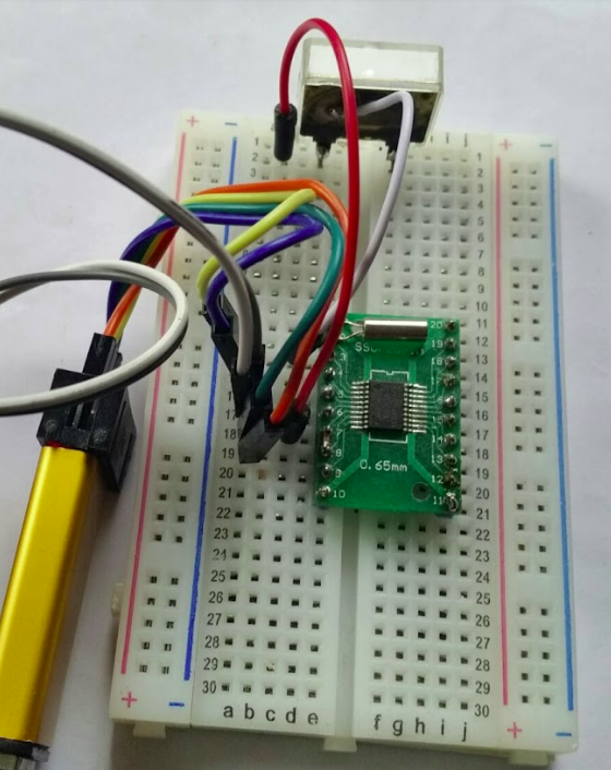
For my experiments I used the nrf24stm8l board that I made some time ago but a chip on a standard "green TSSOP20 breakout PCB" for $0.10 with a crystal soldered to pins 1 and 2 also works (caps were not needed when I tried it):
The write-up gets started with the LSE and the beeper peripheral. Using the beeper is a good test for a crystal oscillator since one can hear the crystal start up! The next experiment introduces the RTC peripheral with a basic example for configuration, initialization and use. -
A debug console in 4 lines of code
10/25/2020 at 08:23 • 0 commentsA Forth system on a $0.20 MCU like the STM8S003F3 with 8K ROM and 1K RAM can offer surprising advantages. Based on an idea I found in the ROBOFORTH II tutorial I added of just 4 lines to the latest STM8 eForth release to provide a very simple debug console that allows examining the state of a Forth program in the middle of the execution
Here is a simple example:
#require BYE
: test ( n -- )
  FOR
    I DUP . 2 MOD 0= IF
      CR ."  Break - mind the stack - continue with BYE" CR
      OUTER THEN
  NEXT ."  done"
;
A debug session on a STM8S003F3, where a "FOR ... NEXT" loop is terminated manually by changing the loop counter on the return stack ($3FF growing down), may look like this:
66 7 test 7 6
 Break - mind the stack - continue with BYE
$03F0 10 dump
 3F0  23  0  0  A 8D 1E 8D 12  1 1D  0  6 8D 1E 8D 12  1_______________ ok
bye 5 4
 Break - mind the stack - continue with BYE
$03F0 10 dump
 3F0  23  0  0  A 8D 1E 8D 12  1 1D  0  4 8D 1E 8D 12  1_______________ ok
$3FA ? 4 ok
0 $3FA ! ok
bye done ok
. 66 ok
Note that a single misspelled word will clear both the data and the return stacks. This will not only reset the console but it will terminate the program and typing BYE in this situation will crash the system! There is clearly room for improvement in the implementation of the library word BYE here.
Edit: here is an improved version of BYE, one that will show a more friendly behavior:
#require OUTER
: BYE ( -- ) [
  \ exit the interpreter on the condition that OUTER was called
  $1605 ,           \ LDW Y,(5,SP)
  $905A ,           \ DECW Y
  $905A ,           \ DECW Y
  $90FE ,           \ LDW  Y,(Y)
  $90A3 , ' OUTER , \ CPW Y,#OUTER
  $2604 ,           \ JRNE +4
  $9085 ,           \ POPW Y
  $9085 ,           \ POPW Y
  ]
;
-
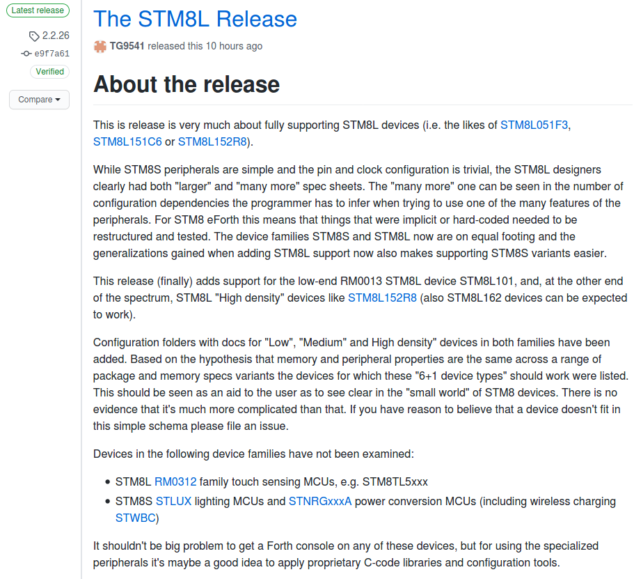
STM8 eForth 2.2.26: The STM8L Release
10/24/2020 at 09:26 • 0 commentsI released STM8 eForth 2.2.26 that adds support for all STM8S "Mainstream" and STM8L "Low Power" devices, at least that's what I assume.
No, I didn't test all the 40 STM8S variants, 37 STM8L variants and none of the 47 STM8AF or STM8AL variants listed here. Instead I looked for evidence what's really the difference between all those devices and thus identified two-and-a-half families (STM8S, STM8L and RM0013-STM8L) with "Low", "Medium" and "High density" devices - and that amounts to just 7 STM8 configurations. The rest is specs and marketing "Product Lines".
Read more about this in the STM8 eForth 2.2.26 Release Notes!
-
A new STM8 eForth pre-release 2.2.26.pr3 is available
09/27/2020 at 12:49 • 0 commentsThe goal of this release to improve STM8L, and to support all STM8L devices, is getting closer.
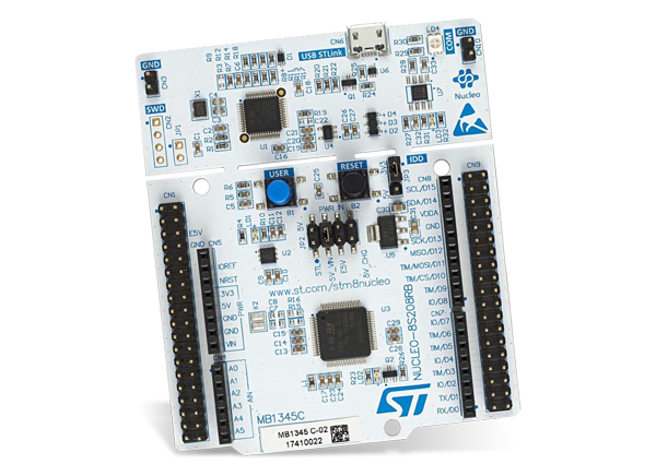
I could need some help with testing support for STM8L High Density devices: there is test code in the repository but I don't have a board (yet).
![]()
So, if you have a NUCLEO-8L152R8 or a similar board with an STM8L High Density chip (e.g. the STM8L152R8 or a also a similar STM8L Medium+ Density chip) I'd be happy to hear from you.
The GitHub issue is here.
-
OpenOCD config files for STM8L Low Density Devices
09/25/2020 at 05:32 • 0 commentsFor RM0031 STM8L Low Density devices (e.g. STM8L051F3 or STM8L050J3) I'm using the following OpenOCD target configuration:
#config script for STM8L051

set FLASHEND 0x9FFF
set BLOCKSIZE 0x40
set EEPROMSTART 0x1000
set EEPROMEND 0x10ff

proc stm8_reset_rop {} {
   mwb 0x4800 0xaa
   mwb 0x4800 0xaa
   reset halt
}

source [find target/stm8l.cfg]
For STM8L101 family devices (i.e. STM8L101F3 or STM8L001J3) the following configuration works for me:
#config script for STM8L101

set FLASHEND 0x9FFF
set BLOCKSIZE 0x40

proc stm8_reset_rop {} {
   mwb 0x4800 0x00
   reset halt
}

source [find target/stm8l.cfg]
I didn't bother about the EEPROM because for all practical purposes the memory blocks designated as "DATA EEPROM" behave like Flash ROM.
My OpenOCD version is "Open On-Chip Debugger 0.10.0+dev-01404-g3934483-dirty". Using OpenOCD I could reset chips such that they consequently worked with STM8FLASH.
-
STM8L001J3M3: another SOP-8 µC runs STM8 eForth
09/22/2020 at 19:47 • 0 commentsFlashing an STM8L001J3M3 never worked for me and I had given up - until debugging an STM8L101F3 with OpenOCD and stm8-gdb showed that I had been chasing a phantom.
I figured that clearing the chip might help but that didn't work, until now: the OpenOCD STM8L example target configuration had RESET ROP (Read-Out Protection) wrong!
EDIT: It's true that the reset routine in the STM8L152.cfg is wrong ... for the STM8L101 family, not for STM8L051 Low Density devices! A file stm8l101.cfg should simply use the stm8_clear_rop code in stm8_clear_rop and that's it.
Fortunately, OpenOCD uses Jim, a TCL subset, for configuration and writing a new "stm8_clear_rop" was quickly done:
#config script for STM8L101

set FLASHEND 0x9FFF
set BLOCKSIZE 0x40

proc stm8_reset_rop {} {
   mwb 0x4800 0xaa
   mwb 0x4800 0xaa
   reset halt
}

proc stm8_clear_rop {} {
   mwb 0x4800 0x00
   reset halt
}

source [find target/stm8l.cfg]
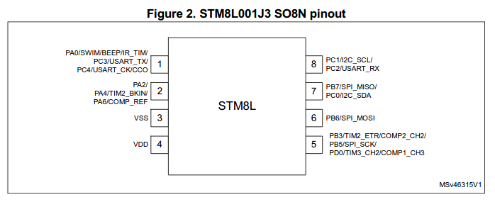
After typing the new command on the OpenOCD telnet console programming just worked!A STM8L001J3M3 is basically a STM8L101 chip in a SOP-8 package.
The problem with this thing is that there is
- a fair chance to lock the chip up by setting any of the GPIOs PA0, PC3 or PC4 to output mode after reset so that PA0/SWIM no longer works
- UART TX is on PC3 - this obviously means "output mode"
- there is no NRST to back you up if you made a mistake
The STM8L101F3 code works around this by *not* configuring PC3 to push pull - the STM8L101F3 binary uses a weak pull-up and active low signaling. It's possible that the pull-up is too weak, but an external 4k7 pull-up will help.
EDIT:
I just tested a Forth console through the simulated serial interface: it works nicely! This means that at least the core functionality of GPIOs and TIM4 (interrupts, peripheral registers) are compatible with the STM8L051 STM8L Low Density devices.
I'm using the following genconf.inc UART section:
        HALF_DUPLEX      = 0    ; Use UART in half duplex mode
        HAS_TXUART       = 0    ; UART TXD, word TX!
        HAS_RXUART       = 0    ; UART RXD, word ?RX
        HAS_TXSIM        = 1    ; Enable TxD via GPIO/TIM4, word TXGP!
        HAS_RXSIM        = 1    ; Enable RxD via GPIO/TIM4, word ?RXGP
        PSIM     = PORTB        ; Port for UART simulation
        PNRX             = 6    ; Port GPIO# for HAS_RXDSIM
        PNTX             = 7    ; Port GPIO# for HAS_TXDSIM
It's also possible to use the simulated port half-duplex mode (which means that RX/TX and SWIM should get along fine on pin1.
-
STM8L101F3: experimental support added to STM8 eForth
09/21/2020 at 06:00 • 0 commentsI merged support for the STM8L101F3 yesterday. For very low power applications the chip is definitely worth looking at (the datasheet claims that it needs around 6µA at 38kHz clock when running from RAM).
New are:
- the STM8L101F3 board support folder
- the new target architecture STM8L_101 in stm8ldevice.inc, and
- STM8L101.efr for creating register constants with e4thcom or codeload.py
The BG task works now: timer register addresses are different from other STM8L devices. That's why it will be necessary to use "\res MCU: STM8L101" for many use cases (not for getting GPIO symbols, though).
I also managed to download the code with stm8flash (!). In case someone wants to try it, here is how to wire the chip:
![]()
What's still missing is a working STM8L001J3M3 based system. The one chip on my breadboard works when I change bytes in the Flash ROM in an OpenOCD terminal session (commands mdb and mwb) but writing an ELF file with stm8-gdb stops after the first four bytes. I'm confident that there is a spare chip in the basement...
It definitively looks like the STM8L101 jinx (or self-inflicted failure) is halfway broken. -
STM8L101F3L3: first STM8 eForth prompt
09/19/2020 at 14:35 • 0 commentsThanks to OpenOCD and GDB: STM8L101 now works!
Besides resolving the problem of actually flashing this chip (I never managed to do that with STM8FLASH), and finding the right configuration for OpenOCD (see the previous log entry), setting the SP to a valid address for this chip (1.5K RAM!) resulted in a prompt (GDB again proved helpfull).
For now I'm using the following target.inc:
;       STM8L101F3 device and memory layout configuration

        TARGET = STM8L051F3     ; let's use this for now - to be fixed later

        RAMEND =        0x05FF  ; "RAMEND" system (return) stack, growing down
        EEPROMBASE =    0x1000  ; "EESTART" EEPROM start address (not really)
        EEPROMEND =     0x10FF  ; "EEEND" 256 bytes EEPROM (see datasheet...)
        FLASHEND =      0x9FFF  ; "FLASHEND" 8K devices

        FORTHRAM =      0x0030  ; Start of RAM controlled by Forth
        UPPLOC  =       0x0060  ; UPP (user/system area) location for 1K RAM
        CTOPLOC =       0x0080  ; CTOP (user dictionary) location for 1K RAM
        SPPLOC  =       0x0550  ; SPP (data stack top), TIB start
        RPPLOC  =       RAMEND  ; RPP (return stack top)
Here is a initialization code snippet of boardcore.inc that enables TX push-pull:
;       BOARDINIT  ( -- )
;       Init board GPIO (except COM ports)

BOARDINIT:
        ; Board I/O initialization: enable USART TX->PC3, RX->PC2
        MOV     CLK_PCKENR1,#0x21
        BSET    PC_DDR,#3
        BSET    PC_CR1,#3
        RET
There are some points that need to be worked on (e.g. BG, EEPROM, RAM layout) and many things are untested. All the important bits works, e.g. writing to NVM!
This means that I'll have to review many docs that state that it's unlikely that STM8 eForth will ever support this chip.
eForth for cheap STM8S gadgets
Turn cheap modules from AliExpress into interactive development kits!