 Alex
Alex-
1Scheme of board
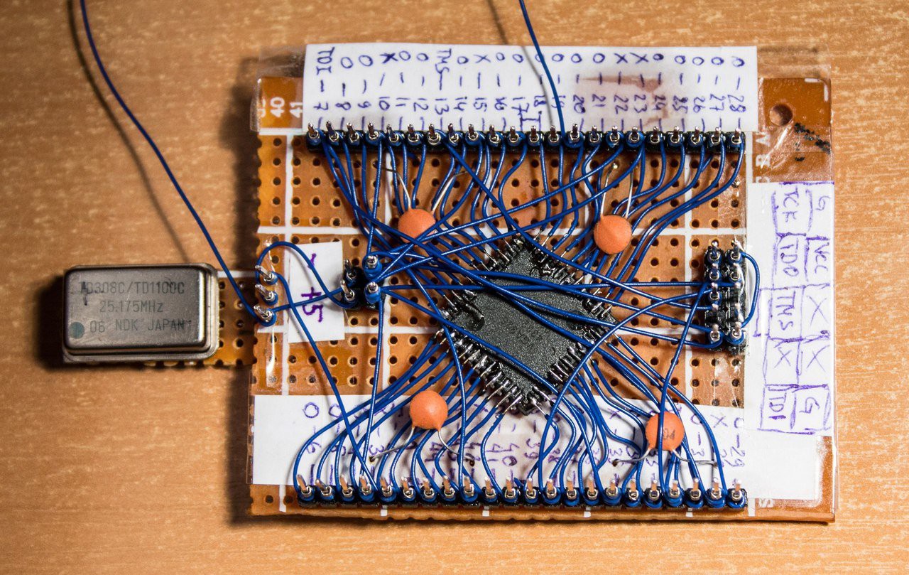
This is a prototype from scratch. Therefore, I did not make a scheme.
I connected all the pins of the CPLD with the pins on the ends of the board. Instead of soldering, I used a wire wrapping. Soldered wires only to FPGA pins.
I attached a description of each pin of the board. See PDF of MAX 7000 series.
After that it became known to which pins to supply voltage. In FPGA are several VCC inputs. I combined them and brought them to a separate pin - VCC/GND, to which I will feed the entire board. The chip works from 5 volts. I shunted each separate VCC input with a capacitor.
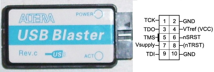
Out of 10 pins, I made a programming connector. Attach pin description. With the wrapping, I connected the corresponding pins of FPGA and connector.
![]()
A minimum of actions, but it is ready to work. It is already possible to flash the firmware and it can work singly.
![]()
FPGA board - it's so easy! ;)
-
2FPGA Based CW transmitter
The FPGA evaluation board - Frankenstein
In old PCB's i found a low-capacity FPGA(CPLD) - EPM7064. I decided to make a small evaluation board.
Discussions
Become a Hackaday.io Member
Create an account to leave a comment. Already have an account? Log In.