Jeremy
-
New Boards, Changes & Testers
10/04/2019 at 13:35 • 5 comments![]()
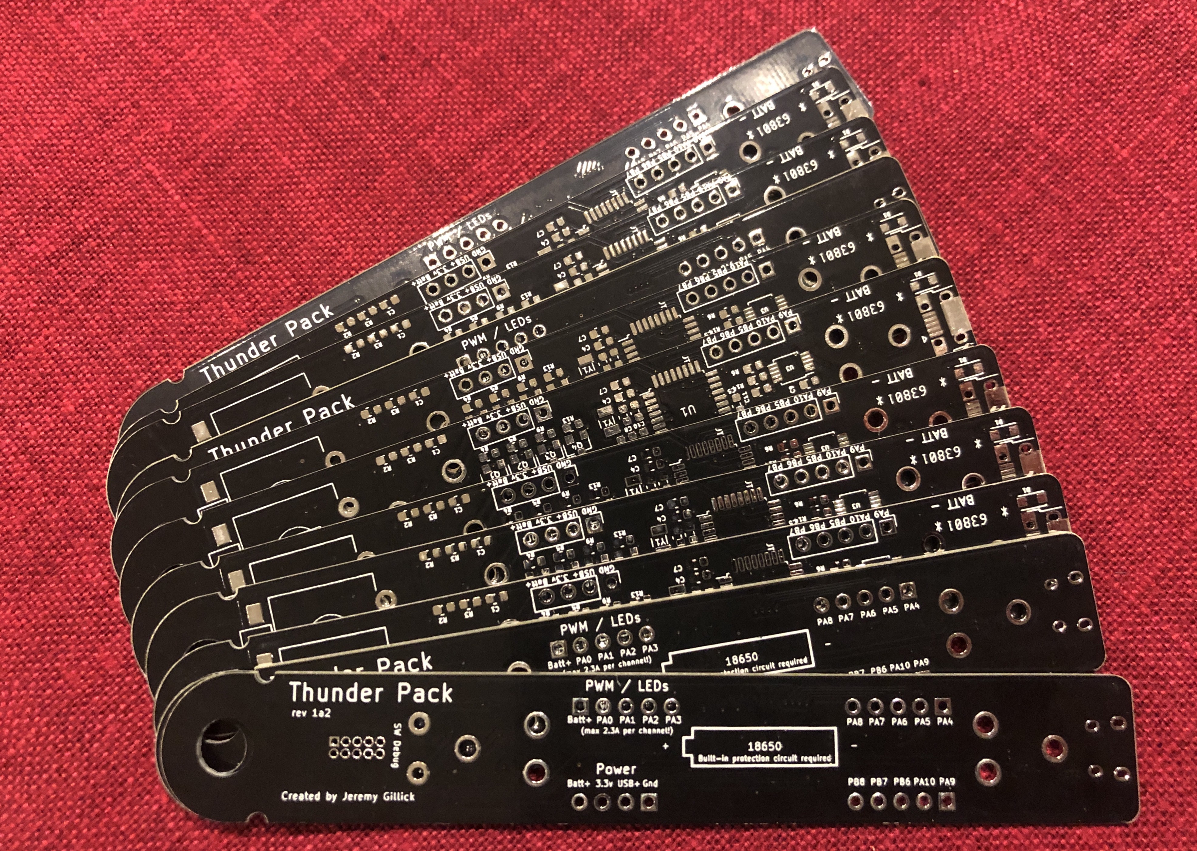
The boards have arrived! I haven't assembled any yet, but everything is feeling a lot more polished.
Beta Testers
Now that the boards are close to completion, I've reached out to some friends and asked them to give them a spin and put them through their paces. I'm excited to get their feedback.
If you're interested to be a beta tester, let me know and I'll help you get setup.
Now 100% more dongle & sewable
The new batch has a hole at the end so it can be hung from a carabiner and notches if it will be sewn to something. The dongle hole can be removes from the board with a pair of diagonal cutters, if it's unnecessary.
Debug Changes + More GPIO
When I moved from 4 layers to 2 layers, space got tight and I had to move the JTAG/SWD pins to the bottom of the board, under the switch (assuming you'd have the switch on top and the debug headers on the bottom). At the time I thought this was a clever way to save some space and keep the layout tidy.
While waiting for the new round of boards, I've been working on writing a decent WS2812B addressable LED example and have been using the debugging interface quite a lot. It's become clear that having the debug pins on the bottom means you cannot debug AND be on a breadboard; which is inconvenient.
So last night I rerouted things.
Now, instead of a dedicated JTAG/SWD block, the necessary 3 pins (reset, PA13, PA4) have been added to the GPIO rows. The happy side-effect is now the board has 2 additional GPIO pins to use!
Next Round of Boards...
I'm controlling my twitchy finger from ordering a new batch of boards with the latest routing. First, I want to build a couple boards from this batch, run them through some tests and get the WS2812B example working.
-
Progress!
09/20/2019 at 17:41 • 0 comments![]()
This is one of those projects that I've been casually working on for the past couple years. Every few months I pick it up, iterate on it a bit, and then put it away. Well, the past few months have seen a great deal of progress and I'm really happy with how far it's come.
In fact, I took one of the recent iterations of it to Burning Man and it survived the week in the harsh elements beautifully. Nothing beats some real-world testing.
Here's a brief rundown on what's been changing:
More Power
I've upgraded the MOSFETS to supply max 2.3A per PWM channel (there are 4 PWM channels!!! You know, so you can drive really big LEDs or just a long string of them. (however, you're still limited by the battery voltage)
The lithium battery charger IC has been changed to more than double the charging current from 500mA to 1.1A.
So Many Example Programs
II've been going crazy writing examples for the board across 4 different popular HAL libraries:
- STM32Cube (Official STM32 HAL lib)
- Arduino
- LibOpenCM3
- ChibiOS
My goal is to have the same examples for each HAL (with some exceptions) so people can compare 1:1 how the libraries differ. It could even be a useful tool for people looking to switch from one library to another (maybe someone familiar with Arduino wants to get closer to the bare metal).
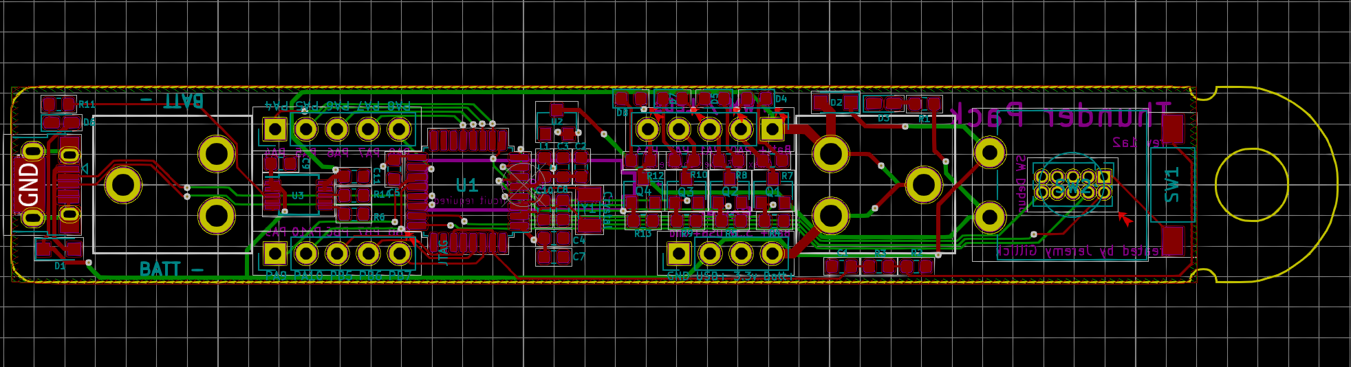
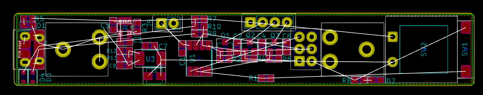
PCB: 2-Layer -> 4-Layer -> 2-Layer
![]()
Even though the overall circuit design isn't too complicated, it can be challenging to effectively route everything on such a narrow board. After reading Hackaday's article on 4-layer PCBs, I decided to give 4 layers a try. It truly made routing the PCB so much easier!
The only problem, though, is the cost. It's still twice as expensive as a 2 layer board, and even more with some PCB houses. For a prototype run, it averages out to $8+/board just for the PCB. Because I want this board to be economical and accessible to anyone, I've decided to switch back to the 2-layer design (although, I could be convinced to keep 4-layers).
The latest 2-layer redesign feels fine, however, I'm still a long way from from being a PCB designing expert. So if anyone is interested in taking a look at the latest iteration, I'd love feedback:
Name Change
I was never really happy with calling the project "Lit Fist". It seemed to pigeonhole it as purely an LED controller. Even though that was the original goal of this project, it has been expanded to be much more than that. Now I see it as a general purpose battery-powered, ARM board with 4 high current outputs and 10 GPIOs. With that in mind, the name has been changed to "Thunder Pack". It still makes for a pretty awesome personal LED controller for wearable projects.
What's Next?
This morning I submitted an order for a fresh run of prototype boards with the new 2-layer design. Now comes the part that I hate...waiting for the PCBs (it's like waiting for Christmas as a kid). When they arrive and if they work as expected, we'll be at a place to call this project feature complete! Until then, I'll keep myself busy writing documentation and coming up with more examples. Stay tuned.
-
Walking sideways to feature creep
10/22/2018 at 00:42 • 0 commentsNot long after I posted the project log "The anatomy of feature creep", @Xasin posted a comment suggesting that I try something other than an AVR chip for this project. For example, many ARM chips have a built-in USB peripheral and bootloader, which would remove some of the complexity & hardware from the previous plan.
I have been looking for an excuse to play with ARM chips and this was all I needed to go foraging down the path to learn everything I could. ARM is very different than AVR and I spent several days with my head spinning trying to figure everything out.
This may have removed some hardware from the design, but replaced it with some new mental gymnastics.
Which Chip?
I started with the STM32F070RB (via a Nucleo-64 dev board). From what I could find, the STM32 line of chips has a great following and quite a bit of online support. I've been really enjoying playing with this chip, so far. The only problem is that it doesn't have an integrated EEPROM; which the final device will need.
This week I'll be giving the STM32L053R8 a try. It looks very similar to the F070, and has an EEPROM built-in. If it works, it'll have everything I need in a single chip.
The original suggestion from @Xasin was to use a ESP32 Pico for this project and I'll be giving that dev board a try soon. This chip would give the project wifi and bluetooth, however, I'd have to add a UART/USB bridge and an external EEPROM chip.
Software Stack
Here are the tools I'm using for ARM development:
- GCC toolchain
- VS Code IDE
- ChibiOS RTOS & HAL
IDE
I tried to use Eclipse, I really did. My problem is, I really f***ing hate eclipse. It's large and clunky and I'm just used to more streamlined IDEs. When I use eclipse, I feel like I spend more time dealing with the IDE than actually working.
I read about people using Visual Studio Code and decided to give it a try. Once I got it up and running I was floored by the level of integration it has with ARM development through the plugins. Everything from compiling & flashing to debugging & stepping through the execution of the program is all in the IDE.
ChibiOS
This part is probably complete overkill. Do I really need a RTOS for fading some LEDs? Probably not...but, it does make fading without blocking a hell of a lot nicer than traditional methods. Also, the HAL it includes for interfacing chips is quite nice.
What's Next?
After I prototype a little more with the dev boards, I'll decide on a chip and send off another order to OSH Park for more purple PCBs.
-
The anatomy of feature creep
09/11/2018 at 01:29 • 0 commentsThe first version of the controller worked pretty well and had just a couple small things I wanted to improve on. It should be an easy upgrade, right? Well, my friends, welcome to a journey down feature creep road.
My primary gripe was that the Attiny10, although tiny, doesn't have an on-board EEPROM to save the last LED mode that was used. No worries, we can upgrade to the Attiny85 just fine.
Just move some things around the board to make room, and we're good to go, right?
Well, now that we have an Attiny85, we might as well use all PWM outputs so the controller can do RGB. Just throw a couple more mosfets in there.
While we're at it, programming via the ISP isn't super convenient and it's completely inaccessible when the device is wrapped in shrink tubing (my cheap/compact enclosure to keep everything together). The board already has a USB port for charging the battery, why not use it to programmed the attiny? Micronucleus is a pretty well trodden USB bootloader for the attiny range, just wire up the USB port to the Attiny85 and we should be good to go, right?
Not so fast! Unfortunately, micronucleus needs a minimum of 12 Mhz to work and the Attiny85 datasheet says it needs at least 4.5V to run more than 10Mhz -- we're not going to get that directly from a single lithium cell.
That's fine, we'll just add boost converter to raise the voltage to 5V 1A. We'll also need to add a couple simple schottky diodes to keep the battery and USB voltage from each other.
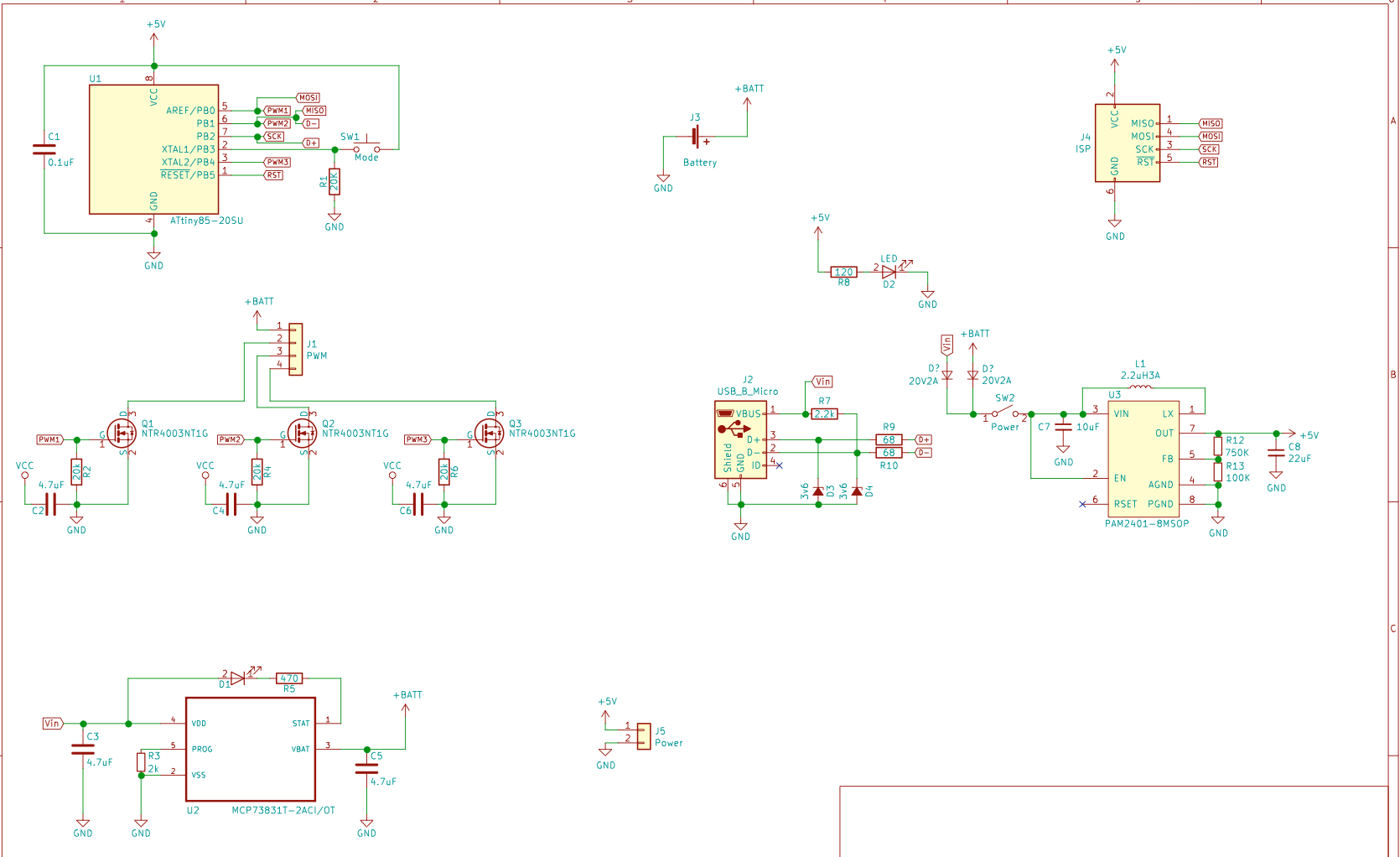
And now we have:
- Attiny85 - microcontroller
- 3 mosfets for LEDs
- PAM2401 - boost converter
- MCP73831T - lithium cell charger
- And all the accompanying components.
Here we go, what could possibly go wrong?
![]()
![]()
-
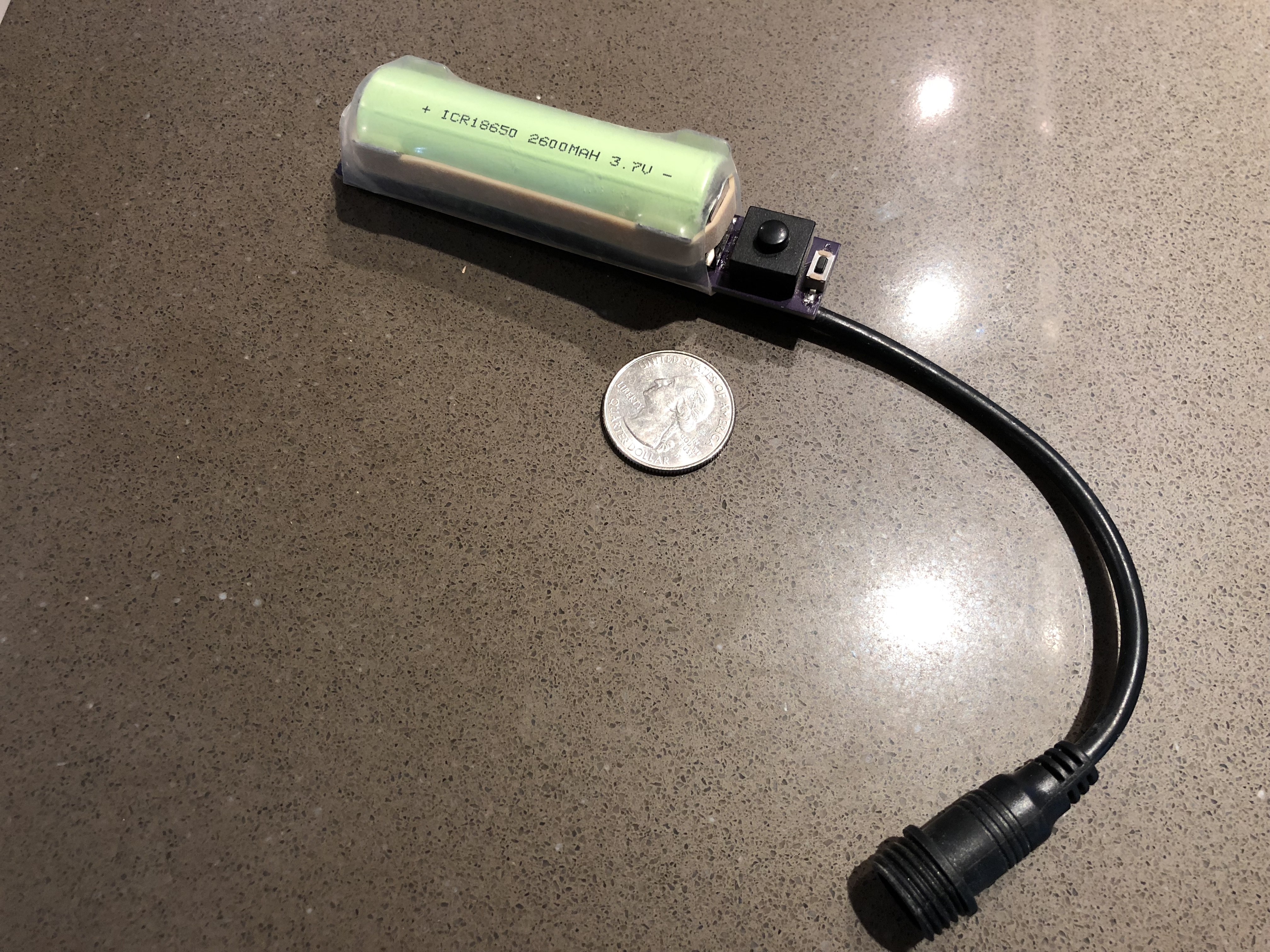
Rev 1 - Attiny10
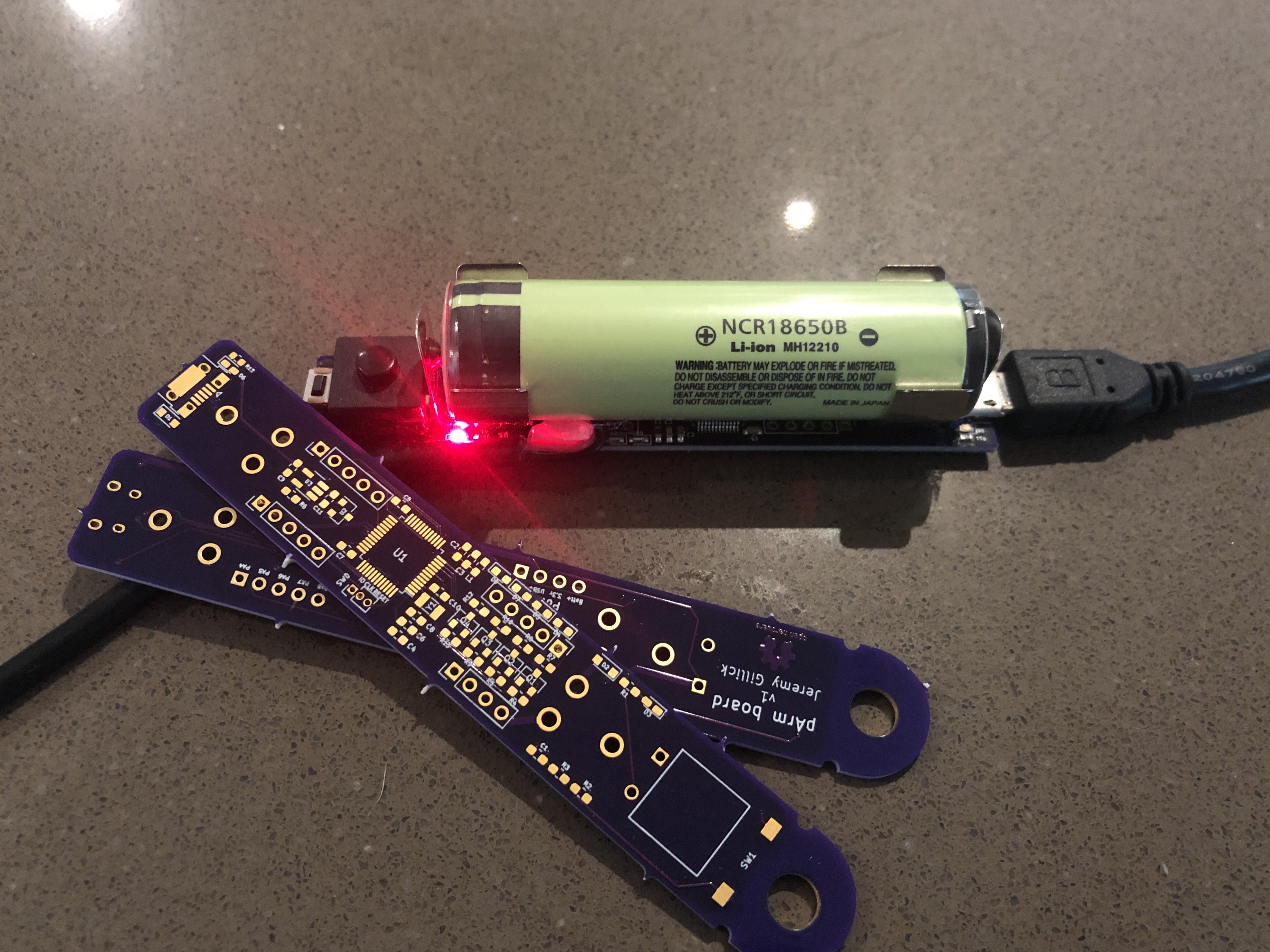
09/11/2018 at 01:15 • 0 commentsThis was the first version. It has a itty bitty attiny10 driving it. This was the first time I'd worked with an attiny10 and it was a good experiment. It was driving 1 meter (50 LEDs) of SparkFun's sewable LED ribbon and with that battery, it was fading it in and out for about 24 hours on a single charge.
![]()
Pros
- Rugged (held up to over a week of use at Burning Man)
- Long battery life.
- Compact
- Charges from by USB
Cons
- Can only program it with an AVR ICE tool.
- Does not remember the last LED animation mode that was used. (attiny10 has no EEPROM).
Programming it via ISP with an AVR ICE was fine, but it wouldn't make it very easy to work on, if I wanted to make any last minute tweaks in the field. Also, we live in a time of USB bootloaders and I have some free time on my hands.
Thunder Pack
A kick-ass high-power ARM board with everything you need -- and small enough to fit in your pocket.