Close
0%
0%

ESP8266 Lua Tutorial, Part 2

Follow along as we dive further into our NodeMCU adventure!

Public Chat
Similar projects worth following

Take a look at Part 1 of this tutorial series:

ESP8266 SDK TutorialLearn how to use the ESP8266 SDK. This is what the pros use!
ESP8266 Lua/NodeMCU TutorialA look at the NodeMCU Lua interpreter for the ESP8266.  Learn how to get to Blinky!
ESP8266 Arduino TutorialUse the Arduino IDE to simplify development and get up to speed very quickly!

And here's the links to the other tutorials in Part 2:

ESP8266 SDK TutorialLooking at using the linker to get PWM, and the included I2C libraries
ESP8266 Lua/NodeMCU Tutorial (You are here)Using PWM and I2C with Lua!
ESP8266 Arduino Tutorial Using the Wire library for I2C, and AnalogWrite for fading!

Links to Part 3

ESP8266 SDK TutorialUsing MQTT to develop an IoT device
ESP8266 Lua/NodeMCU TutorialUsing the NodeMCU MQTT module to communicate with a cloud data service
ESP8266 Arduino TutorialWe use the simpler, more widely available HTTP protocol to log data to the cloud

Getting Help

If you run into trouble while following these tutorials, you have a few different options:

  • Ask in the discussion area below the article
  • Join the ##esp8266 channel on Freenode IRC and ping me (MrAureliusR) or ask anyone who is in there
  • Post on the ESP8266 Community Forums (note it can take a while to get a response!)
  • Send me a private message here on Hackaday

Lua Part 2: PWM and I2C

What is PWM?

Pulse-width modulation (PWM) is a method to control the average voltage of a signal without using analog means, such as a digital-to-analog converter (DAC) or digital potentiometer. By producing a square wave and changing the duty cycle, we control the amount of power delivered. The duty cycle is the ratio between the time the signal is in the high state and the low state. Think of it like an integral -- we are changing the area under the curve, which is equivalent to power. Take a look at this diagram:
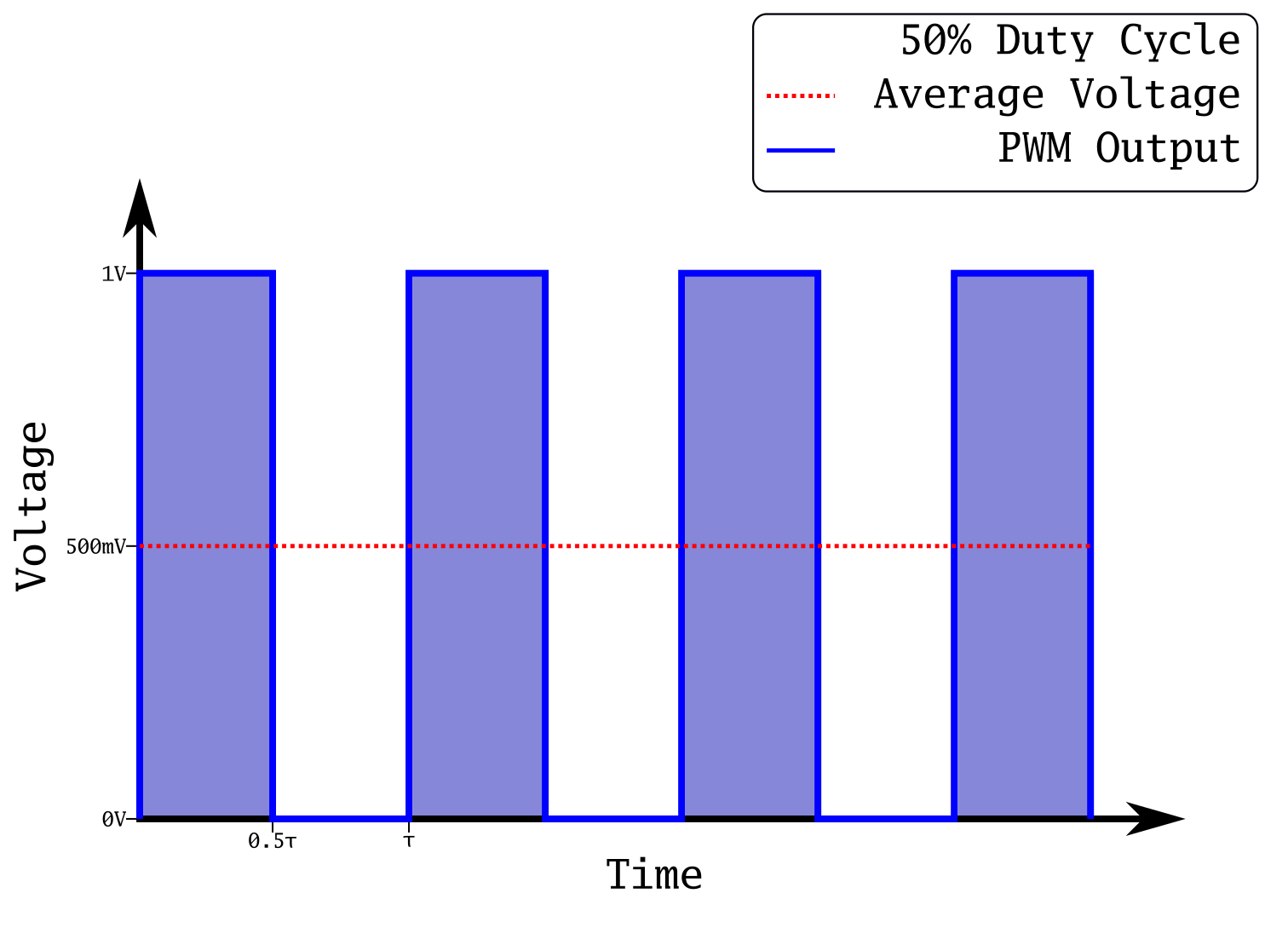
Square wave at 50% duty cycle

This is a plot of a square wave at 50% duty cycle. This means it spends half of its period (τ) in its high state, and the other half in its low state. In the case of this output, that means 1 V and 0 V respectively. The power transmitted is the integral of this plot, which is represented by the blue shading under the curve. Notice how that area is equal to the area during the low state; this is how we know it's at 50%. This has the effect of producing an average voltage of 500 mV. If we were to produce an analog output at 500 mV, and take the integral, it would be equal to the integral of this PWM output. This is extremely useful, as creating square waves is simple with a microcontroller, whereas creating analog voltages requires many extra components. 

What happens if we reduce that output to 30%?
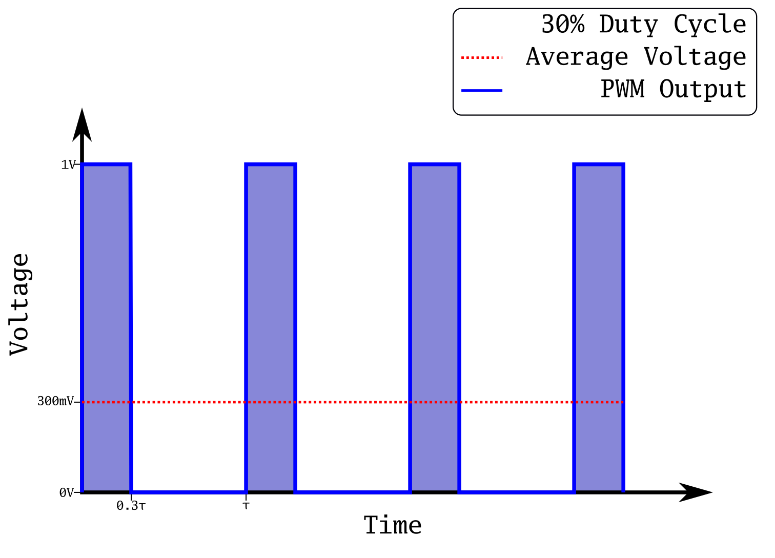
Square wave with 30% duty cycle

Now the on state is only on for 30% of the time. Our average voltage has now dropped to 300 mV. We have reduced the power sent out of our microcontroller pin just by changing the duty cycle of a square wave! If you are into math, you can prove that the analog voltage and the square wave are equivalent:

T is the period in seconds, and sgn() is the sign function. It's a simple way to get a perfect square wave on a plot. The integral of 0.5 from 0 to 20 is exactly 10, and the integral of the square wave will be almost exactly 10 as well. They will get closer with a faster period, and with more cycles. If you were to integrate to infinity, they would be exactly the same.

This is a common technique to control things like LED brightness, servo position, and buzzers. We are going to use it to fade an LED in the tutorial section below.

A quick side note about brightness of LEDs and PWM. The way human eyes respond to light is non-linear. Especially when LEDs are near the limit of their brightness, adding more current has a very small effect on the apparent brightness. So in order to scale the current going...

Read more »

  • 1
    Fading an LED

    In Part 1 of this series, we used an online build service to create our firmware. One of the modules we selected was the PWM module. This module allows us to configure PWM on any of the available GPIO pins which support it. We can configure the frequency and duty cycle, and easily start and stop PWM output. The first function we will look at is pwm.setup().

    The setup function takes 3 parameters: the pin you want to use (1-12), the frequency of the PWM output (1-1000 Hz), and the duty cycle you want (0-1023). The duty cycle is a 10-bit number, which gives a decent amount of resolution. Remember that the pin numbers used are the NodeMCU pin numbers which do not correspond to the GPIO numbers. Use one of the many charts online to convert between the two. In our example, we are going to use pin 3, which corresponds to GPIO0. If your ESP8266 board has an LED on a different pin, just change the led variable.

    In order to fade the LED up and down, we need to not only set the duty cycle, but change it over time. We want to oscillate between 0 and 1023. The way I've always approached this is to build an extremely simple state machine. We can be in one of two states -- increasing or decreasing. Every time we go through the loop, we check which state we're in and then change the variable which represents the current duty cycle accordingly. Typically I just use a variable called "direction", where 0 is decreasing and 1 is increasing.

    So, in Lua, we just declare three variables: led, curDuty, and direction.

    led = 3 -- GPIO 0
    curDuty = 1023 -- full brightness
    direction = 0 -- decreasing, because we are starting at full

    Remember that the double hyphen in Lua denotes the start of a comment! Now that we have our variables created and initialised, we need to start up the PWM module and pass it the starting values. We do this with the setup() function we just talked about, followed by the pwm.start() function. The start() function just takes the pin we want to start PWM on.

    pwm.setup(led, 1000, curDuty) -- we are using 1000Hz
    pwm.start(led)

     Because we don't ever need to change the PWM frequency, we just pass it a constant value. At this point in the code, the LED will be on with full brightness. Now we need to create a function which operates the simple state machine as outlined previously.

    The state machine needs to do two things: check if the duty cycle has reached its limits (0 or 1023), and operate on the duty cycle variable depending on the state we are in (increasing or decreasing). We wrap this all in a function block so we can use a timer to trigger it on a periodic basis.

    The function is quite simple:

    function fadeLED()
       if curDuty == 1023 then
          direction = 0
       elseif curDuty == 0 then
          direction = 1
       end
       
       if direction == 0 then
          curDuty = curDuty - 1
       elseif direction == 1 then
          curDuty = curDuty + 1
       else
          --should never be reached!
          curDuty = 0
       end
       pwm.setduty(led, curDuty)
    end

    If you are new to programming, I want you to stop and think about why the else statement in the second part of the function should never be reached. We can see that it first checks to see if the duty cycle has hit 1023 or 0, and it sets the direction accordingly (to reverse the fade once we hit full brightness or full darkness). After that, depending on the direction we are going, we simply increase or decrease the duty cycle by 1. You can play around with the speed of the fade by changing the 1 to a different number. After this, we use the setduty() function to set the new duty cycle.

    Pretty simple, so far. However, we need something to actually call this function! Otherwise it won't do anything. As we discussed in part 1, user functions need to be initiated either through timers or tasks. A timer fits our use case perfectly: we want to call this function every so often, say every millisecond. With 1024 levels of brightness, the LED will fade about once a second. The whole cycle will take just over 2 seconds, so it will appear as a nice, slow fade.

    The timer module has a function which makes creating and starting new timers very easy. The function is called alarm(). Again, it's fairly self-explanatory. The first argument is the timer we want to use -- we can have up to 7, numbered 0-6. We'll use the first one, timer 0. The second argument is the period of the timer. This is how long it will wait after the timer starts to call the callback function. The third argument is the type of timer we want. It can be a one-shot timer (a timer that runs once and then stops), a manual timer (must be called manually every time we want to use it) or an automatic timer (keeps running over and over without the program needing to intervene). We want an automatic timer, so the third argument is tmr.ALARM_AUTO. Finally, the last argument is the function we want to call when the timer fires. We end up with this:

    tmr.alarm(0, 1, tmr.ALARM_AUTO, fadeLED)

    Alright, we've got our program ready. Let's get it running!

  • 2
    Upload the code

    I like to keep all my projects in their own folders. If you haven't already, I highly suggest creating a folder in your home directory called workspace. Inside that folder, I have a folder dedicated to all my ESP8266 stuff named, aptly, esp8266. Then, I have a folder in there for each project. If you end up with a lot of projects, you might want to put them all in another subfolder called projects.

    Inside whichever folder you use, start your favourite text editor and create a new file called init.lua. Copy our complete code below into it, making any changes you need. You might need to change the LED pin as we mentioned before.

    led = 3
    curDuty = 1023
    direction = 0
    pwm.setup(led, 1000, curDuty)
    pwm.start(led)
    
    function fadeLED()
       if curDuty == 1023 then
          direction = 0
       elseif curDuty == 0 then
          direction = 1
       end
       
       if direction == 0 then
          curDuty = curDuty - 1
       elseif direction == 1 then
          curDuty = curDuty + 1
       else
          --should never be reached!
          curDuty = 0
       end
       pwm.setduty(led, curDuty)
    end
    
    tmr.alarm(0, 1, tmr.ALARM_AUTO, fadeLED)
    

    Just like in Part 1, we will use the luatool.py tool to upload this to our ESP8266 board running the NodeMCU firmware we built. I won't go over the whole flashing procedure again; if you need a refresher, go back and re-read Part 1. Here is the command we need to use:

    python2 luatool.py --port [port] --src init.lua --dest init.lua --verbose

    You should know what port to use. Typically it will be /dev/ttyUSB0 or similar. Check your /dev folder if you're unsure. Once it has finished writing, you should see your LED fading! If you encounter any errors while programming, reset the board and then run the command again.

    Awesome! Using PWM is a very handy way to display data to the user, especially changing data over time. Now that we've got this technique under our belt, let's take a look at another important NodeMCU module: I2C.

  • 3
    I2C Communication

    In the details section of this project you will find a detailed analysis of the I2C bus and how it works, both electrically and in software. Make sure you read this before proceeding, so you understand what the code is doing. We're going to use the NodeMCU firmware to communicate with a DS3231 real-time clock chip. Whenever you work with a chip, the most important thing to do is read its datasheet. This will give us all the information we need to write our code.

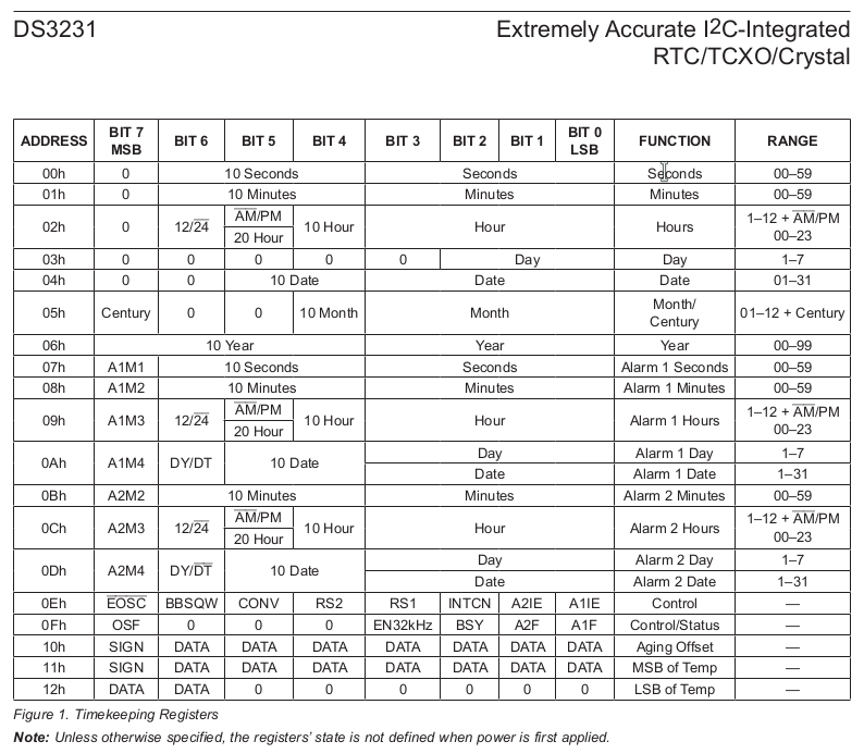
    DS3231 Register Map

    In order to get the RTC to keep time, all we have to do is set the time keeping registers. One of the quirks of many RTC chips is that they store the time as binary-coded decimal. This is a method of representing decimal numbers in hexadecimal. For example, 27 would be 0x27, despite the fact that the value of 0x27 is actually 39. This is mostly a leftover artefact of the earlier microprocessor days when many inputs and outputs were in BCD to make it easier to display or manipulate with external circuitry. However, with modern microcontrollers, it's often more of a hassle as BCD takes up more bits and it also slows down any arithmetic operations.

    We will be using the I2C module of the NodeMCU firmware. It's fairly simple to use, and it abstracts away most of the detail of the hardware, which is great for quick prototyping. The DS3231 datasheet tells us that the 7-bit address of the DS3231 is 0x68. We pass this, along with the pins we want to use for SCL and SDA to the i2c.setup() function. Remember to check the NodeMCU pinout to convert between GPIO numbers and NodeMCU pins. On the Adafruit Feather HUZZAH the SCL and SDA pins are marked on the board; these are GPIO4 and 5, which translate to NodeMCU pins 1 and 2. When we turn this into code, it looks something like this:

    ds3231addr = 0x68
    sclpin = 1
    sdapin = 2
    
    i2c.setup(0, sdapin, sclpin, i2c.slow)

    Only i2c.slow is supported for the speed, which is 100kHz. This is plenty fast enough for our purposes. At this point, the I2C module is initialised and ready to transmit. You'll notice that the address for the DS3231 wasn't passed to the setup function -- this will be used when we go to transmit. The first parameter passed is the id of the i2c module we want to use. Currently the firmware only supports a single module, which is always id 0.

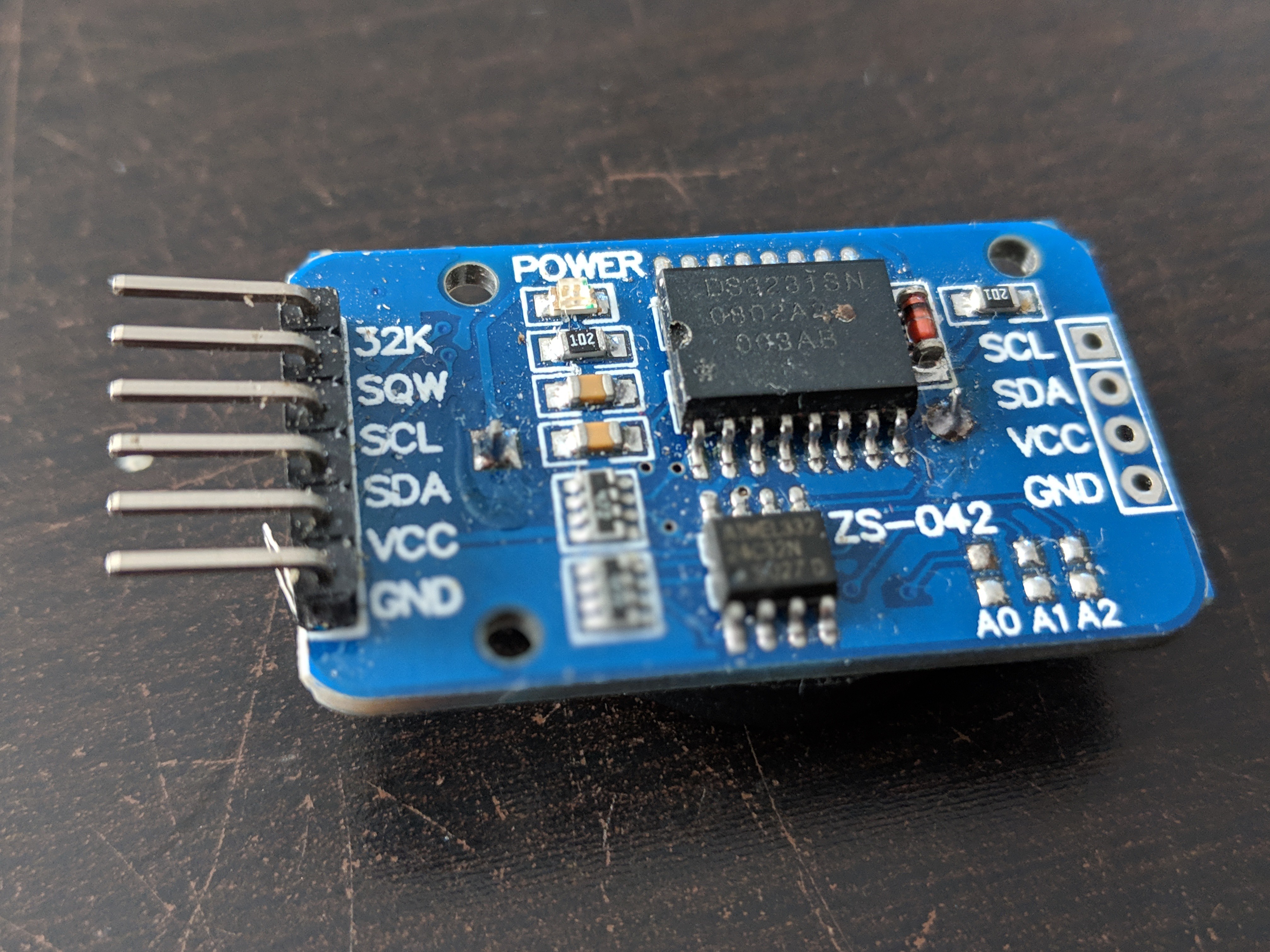
    DS3231 Module
    DS3231 Module

    As a test, let's try writing code to program the time 16:34:12 into the RTC. We need to call the i2c.start() and i2c.address() functions, and then i2c.write() to write the data. Let's take a look:

    i2c.start(0)
    i2c.address(0, ds3231addr, i2c.TRANSMITTER)
    i2c.write(0, 0, 0x12, 0x34, 0x16)
    i2c.stop(0)

    So we send a start condition followed by the write address for the DS3231. We then send the data. We want to start at register 0, so that's the first piece of data we send. This writes 0 into the register address. Almost all I2C devices work with this same concept. You select the register you want, and then you read/write it. Then we send the time. Note the order of the registers, the seconds come first, then the minutes, then the hours. After this is sent, we send a stop condition. That wasn't so hard, was it?

    There's a couple improvements we should make. The i2c.address() function returns true if the chip responded, and false if it didn't. We should check this before sending the data. We should also turn this into a function which will write whatever time is given to it. Also, we also want to create a function which will program the date. We will also need a way to read these values back and display them on the console.

View all 5 instructions

Enjoy this project?

Share

Discussions

Similar Projects

Does this project spark your interest?

Become a member to follow this project and never miss any updates