-
1Using the PWM library with the SDK
The SDK does come with a PWM library, which is great. This makes our task much easier. Using it is a bit convoluted, but it's nothing we can't tackle. We are going to use the same approach as in Part 1: create a function which will be called by an automatic timer periodically. In our function, we will change the duty cycle in order to get a nice smooth fade. Prior to this, we need to set up all the needed variables and get the PWM library initialised.
Let's start by declaring all our variables. We'll create variables for the PWM frequency, the duty cycle both in percent and as an absolute value, and also a variable to keep track of our state (increasing or decreasing). We also need to create the os_timer_t variable for our periodic timer. Because the max duty cycle absolute value changes with frequency, we create a variable for that as well. We'll calculate that value in the user_init function, per the SDK documentation.
// ESP-12 modules have LED on GPIO2. Change to another GPIO
// for other boards.
static os_timer_t ledTimer;
bool ascending = true;
static const uint32_t frequency = 5000; // in hz, so 5kHz
uint32_t maxDuty = 0;
uint8_t ledDutyPercent = 10;
uint8_t *pLedDutyPercent = &ledDutyPercent;
uint32_t ledDuty = 0;
uint32_t *pLedDuty = &ledDuty;
Now we'll build our PWM control function. This will check to see if we've reached our maximum or minimum duty cycle, and switch the direction state if we have. It will also modify the duty cycle, and update the PWM output with the new duty cycle. All in all, it's fairly simple and self-explanatory:
void ICACHE_FLASH_ATTR ledTimer_f(void *args) {
  if(*pLedDutyPercent == 100) {
    ascending = false;
  } else if (*pLedDutyPercent == 0) {
    ascending = true;
  }
  if(ascending == true) {
    (*pLedDutyPercent)++;
  } else if(ascending == false) {
    (*pLedDutyPercent)--;
  }
  *pLedDuty = (uint32_t)((*pLedDutyPercent/100.0) * (float)maxDuty);
  pwm_set_duty(*pLedDuty, 0);
  pwm_start();
}
We simply calculate the new duty cycle value, and update it with the pwm_set_duty() function. After each change we also have to call pwm_start() again, to force an update. Finally, let's look at the user_init function:
void ICACHE_FLASH_ATTR user_init() {
  // init gpio subsytem
  gpio_init();
  maxDuty = (frequency * 1000)/45;
  uint32_t pwmInfo[1][3] = {{PERIPHS_IO_MUX_GPIO2_U,FUNC_GPIO2,2}};
  *pLedDuty = (uint32_t)((float)(ledDutyPercent/100.0) * (float)maxDuty);
  pwm_init(frequency, pLedDuty, 1, pwmInfo);

  // setup timer (20ms, repeating)
  os_timer_setfn(&ledTimer, (os_timer_func_t *)ledTimer_f, NULL);
  os_timer_arm(&ledTimer, 20, 1);
}
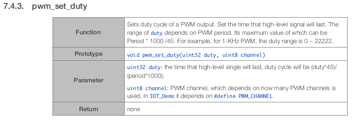
Remember that the first function to be called by the system must be called user_init(). We start by initializing the GPIO system with gpio_init(). Then we calculate the maximum duty cycle value. It follows a slightly odd formula, as given in the SDK documentation:
![]()
The way we tell the PWM library which outputs we want to use is also slightly convoluted. We must create an n*3 dimensional array where n is the number of outputs we want. We're only using one, so we create a [1][3] array. The single row contains an array of three values: which GPIO register to use, the IO reuse of the corresponding pin and the GPIO number. We're using pin 2 as our output, so all our entries are related to GPIO channel 2. We then calculate the max duty cycle value using the above formula, and we pass all this information to the pwm_init() function. Note that the third parameter passed to pwm_init() is the number of PWM channels used, and not the PWM channel to be initialised. This is incorrectly documented and took me a while to figure out.
Finally, we set up our timer for 20ms, pointing to our ledTimer_f() function. This is set as an automatic timer, so after it's armed that's all we need to do! Phew.
-
2PWM Code
Now that we have all the pieces, let's put them all together:
#include <math.h>
#include "ets_sys.h"
#include "osapi.h"
#include "gpio.h"
#include "pwm.h"
#include "os_type.h"

// ESP-12 modules have LED on GPIO2. Change to another GPIO
// for other boards.
static const int pin = 2;
static os_timer_t ledTimer;
bool ascending = true;
static const uint32_t frequency = 5000; // in hz, so 5kHz
uint32_t maxDuty = 0;
uint8_t ledDutyPercent = 10;
uint8_t *pLedDutyPercent = &ledDutyPercent;
uint32_t ledDuty = 0;
uint32_t *pLedDuty = &ledDuty;

void ICACHE_FLASH_ATTR ledTimer_f(void *args) {
  if(*pLedDutyPercent == 100) {
    ascending = false;
  } else if (*pLedDutyPercent == 0) {
    ascending = true;
  }
  if(ascending == true) {
    (*pLedDutyPercent)++;
  } else if(ascending == false) {
    (*pLedDutyPercent)--;
  }
  *pLedDuty = (uint32_t)((*pLedDutyPercent/100.0) * (float)maxDuty);
  pwm_set_duty(*pLedDuty, 0);
  pwm_start();
}

void ICACHE_FLASH_ATTR user_init() {
  // init gpio subsytem
  gpio_init();
  maxDuty = (frequency * 1000)/45;
  uint32_t pwmInfo[1][3] = {{PERIPHS_IO_MUX_GPIO2_U,FUNC_GPIO2,2}};
  *pLedDuty = (uint32_t)((float)(ledDutyPercent/100.0) * (float)maxDuty);
  pwm_init(frequency, pLedDuty, 1, pwmInfo);

  // setup timer (20ms, repeating)
  os_timer_setfn(&ledTimer, (os_timer_func_t *)ledTimer_f, NULL);
  os_timer_arm(&ledTimer, 20, 1);
}
We can use the Makefile we created in Part 1, but we have to make one small change. If we were to try and compile the code right now, the linker wouldn't know where to find the functions pwm_set_duty() and pwm_start(). So, let's open our Makefile and make one small change:
LDLIBS=-nostdlib -Wl,-Map=output.map -Wl,--start-group -lc -lm -lhal -lpp -llwip -lphy -lnet80211 -lwpa -lmain -lpwm -Wl,--end-group -lgccNotice the addition of -lpwm, the PWM library. Now the linker has all the pieces it needs to compile the code. Just like in part 1, you can compile and flash the code by using the command:
$ make flash
Remember to make sure you have the correct port set in your Makefile. Everything should compile and program smoothly. If it doesn't take a careful look at the errors you get. As always, if you get stuck, refer to the "Getting Help" section in the project description!
-
3Using the I2C library with the SDK
The ESP8266 does not have a hardware I2C module, thus all I2C comms must be done in software. The ESP8266 SDK does include an I2C software implementation, which is handy, and we'll be taking advantage of it. We will be modifying our Makefile again, as well as copying the I2C library file from the ESP8266 NONOS SDK folder.
Start by grabbing i2c_master.c from your ESP SDK folder:
$ cp ~/workspace/ESP8266/esp-open-sdk/ESP8266_NONOS_SDK-2.1.0-18-g61248df/driver_lib/driver/i2c_master.c ~/workspace/ESP8266/C/i2ctime/i2c_master.c
This is how I have my workspace organised, as I've mention previously. However, your layout may vary, and the name of your ESP8266_NONOS_SDK folder will likely be different. We will also need the header file i2c_master.h, though it needs to go in a subfolder called "driver":
$ mkdir ~/workspace/ESP8266/C/i2ctime/driver/
$ cp ~/workspace/ESP8266/esp-open-sdk/ESP8266_NONOS_SDK-2.1.0-18-g61248df/driver_lib/include/driver/i2c_master.h ~/workspace/ESP8266/C/i2ctime/driver/
We also need to update our Makefile so that the i2c_master library gets built and linked into our executable. To do this, we simply add a few new lines to our Makefile:
P=main
CC=xtensa-lx106-elf-gcc
LDLIBS=-nostdlib -ggdb -Wl,-Map=output.map -Wl,--start-group -lm -lc -lhal -lpp -llwip -lphy -lnet80211 -lwpa -lat -lwpa2 -lmain -Wl,--end-group -lgcc
CFLAGS=-I. -mlongcalls -std=gnu11
LDFLAGS=-Teagle.app.v6.ld

all: $(P)

$(P)-0x00000.bin: $(P)
    esptool.py elf2image $^

$(P): $(P).o i2c_master.o

i2c_master.o: i2c_master.c

$(P).o: $(P).c

flash: $(P)-0x00000.bin
    esptool.py --port /dev/feather0 write_flash 0 $(P)-0x00000.bin 0x10000 $(P)-0x10000.bin

clean:
    rm -f $(P) *.o $(P)-0x00000.bin $(P)-0x10000.bin
We tell it that $(P) is made not only from our main.o file, but also from i2c_master.o. The next line gives instructions on how to make i2c_master.o: by compiling i2c_master.c, of course! I also added -std=gnu11 to the CFLAGS as I like to use some of the features of newer versions of C.
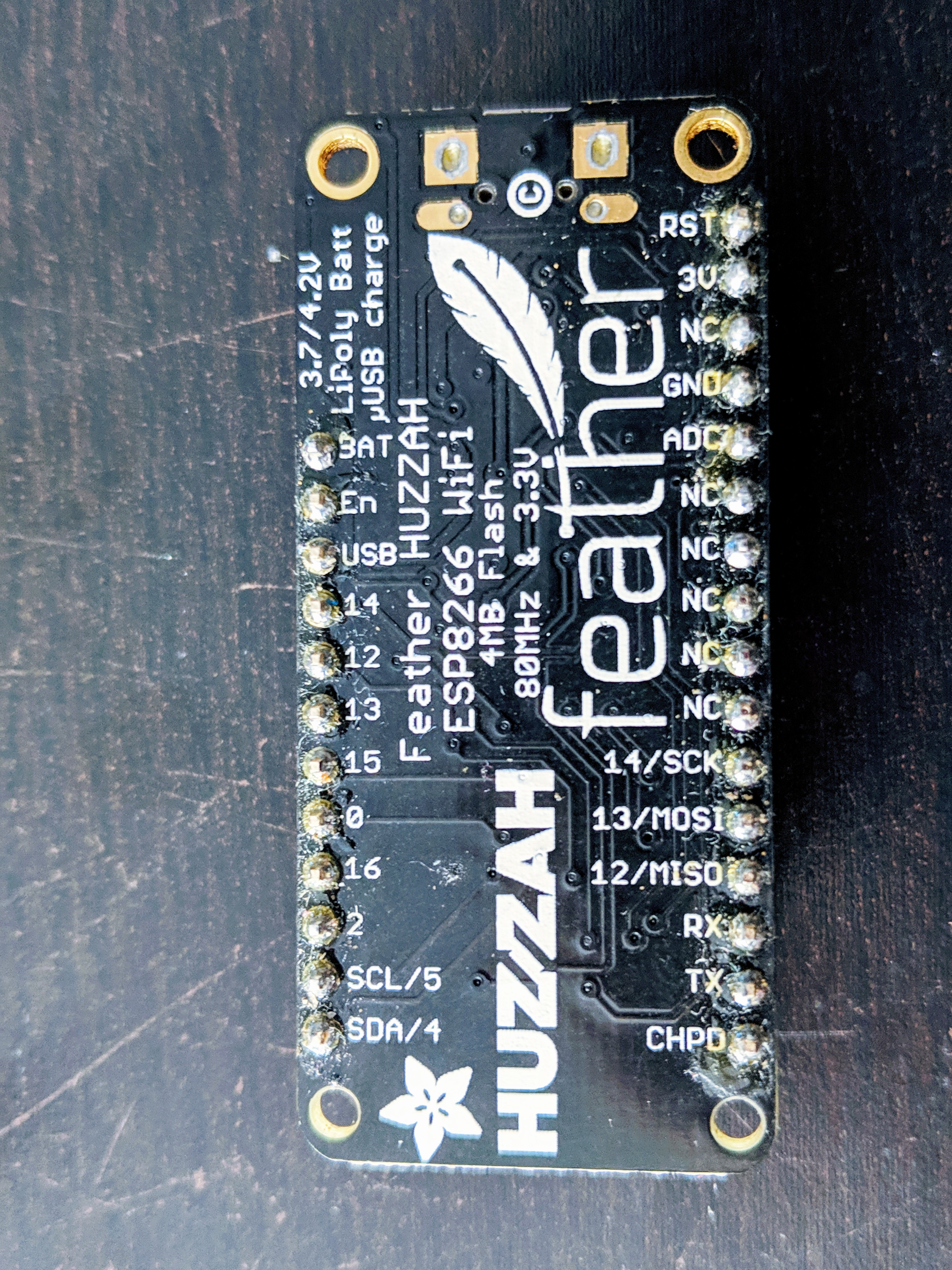
Note that the pin definitions for SCL and SDA are inside i2c_master.h, near the top. These pins are labelled on the back of the Feather:
![]()
Alright, let's dive into the code itself.
-
4I2C Comm Example with DS3231
You can view the entire main.c in a GitLab snippet here. I find with longer code snippets, it's much easier to view it in a separate tab and refer to the instructions. Let's go through it piece by piece.
First of all, we have to include the i2c_master library. We do this by adding
#include "driver/i2c_master.h"to the list of includes at the top of the file. This, plus the changes we made to the Makefile, will enable the I2C library to be built and linked correctly.
The next section includes the address of the real-time clock as well as a struct for it, as well as some defines for I2C communication states.
#define DS3231addr 0x68

#define SUCCESS  0
#define ADDR_ERR 1
#define DATA_ERR 2

static os_timer_t sampleTimer;

typedef struct {
  uint8_t address;
  uint8_t sendBuf[16];
  uint8_t recvBuf[16];
  uint8_t length;
  double temperature;
} ds3231_t;

ds3231_t unit_0;
ds3231_t *pUnit0 = &unit_0;
The defines for SUCCESS, ADDR_ERR and DATA_ERR are codes that can be returned by the I2C functions I wrote so the program can determine what went wrong, or to report success. We will also be using a timer later on, so I create an os_timer_t here as well.
![]()
The DS3231 plugged into a breadboard Because we are working with the DS3231 real-time clock chip in our example, I use the coding style that I typically use for smaller projects with one or more external chips/sensors. I create a struct for that chip to hold information about it. In our case, the struct has the I2C 8-byte address (generated from the 7-bit #define when needed), some variables to act as a receive and transmit buffer for the I2C system, and a variable to hold the length of the transmission or length of the received data. Because the DS3231 also has an internal temperature sensor, I also included that as a double for easy storage of the floating-point number it contains.
After the definition of the struct, we create an instance of the struct, and then create a global pointer to it. This is my sort of haphazard way of using basic object-oriented programming in a language that wasn't designed for it. If you've never used structs before, you can almost think of them as very basic classes. However, they can only hold variables. I highly recommend brushing up on structs if you're not familiar with them.
Now we get to our first function:
LOCAL uint8_t i2cwrite(ds3231_t *unit) {
  unit->address = (DS3231addr << 1); // write address
  if(unit->length > 16) unit->length = 16; // bounds check
  i2c_master_start();
  i2c_master_writeByte(unit->address);
  if(!i2c_master_checkAck()) return ADDR_ERR;
  for(int i = 0; i < unit->length; i++) {
    i2c_master_writeByte(unit->sendBuf[i]);
    if(!i2c_master_checkAck()) return DATA_ERR;
  }
  i2c_master_stop();
  return SUCCESS;
}
This is a simple function that acts as a wrapper around the i2c_master library. It takes a pointer to the ds3231_t created earlier, and returns an error or success code. The first thing we do is set the address that we will be using -- remember that I2C addresses change depending on whether we are reading from or writing to the chip. Because this function is for writing to the chip, we simply shift the DS3231 7-bit address 1 to the left, which leaves us with the 8-bit write address.
Then there is a simple check to make sure we aren't trying to write more than 16 bytes at once, as this would overflow our buffer. We then send a start condition, followed by the write address. We then check and see if the chip acknowledged our transmission: if it didn't, we end the function here and return ADDR_ERR. Otherwise, we continue.
The next section is a loop which takes each byte in the sendBuf[] and sends them one by one, each time checking to see if the chip acknowledges the transmission. If at any time it fails to ack, we return early with DATA_ERR. Otherwise, we finish sending data, send a stop, and return SUCCESS. Pretty simple once it's broken down, right?
The next function is very similar to the write function, with a few extra steps needed:
LOCAL uint8_t i2cread(ds3231_t *unit) {
  unit->address = (DS3231addr << 1); // write address
  i2c_master_start();
  i2c_master_writeByte(unit->address);
  if(!i2c_master_checkAck()) return ADDR_ERR;
  i2c_master_writeByte(unit->sendBuf[0]); // send register to read from
  if(!i2c_master_checkAck()) return DATA_ERR;

  unit->address = (DS3231addr << 1) | 1; // read address
  i2c_master_start();
  i2c_master_writeByte(unit->address);
  if(!i2c_master_checkAck()) return ADDR_ERR;

  if(unit->length > 16) unit->length = 16;
  for(int i = 0; i < unit->length; i++) {
    unit->recvBuf[i] = i2c_master_readByte();
    if(i < unit->length - 1) i2c_master_send_ack();
    else i2c_master_send_nack();
  }
  i2c_master_stop();
  return SUCCESS;
}
Similarly to the write function, the first thing we do is generate the 8-bit write address. This is because almost all I2C reads will start with a write to tell the chip which register we want to read from. In our case, the next few lines are essentially an abbreviated version of the write function: we send a start, then the address, then the register we want to read from (which is stored in sendBuf[0]), all the while making sure the chip is responding to our commands.
Once that step is finished, we then generate the read address, and then send a start command followed by that address, checking for ack again. We then go through a similar loop to the loop in the write function, only this time we are reading bytes from the DS3231 until we have read the number of bytes requested. At that point, we send a nack, and then a stop. Notice we also do a bounds check before the loop to make sure we aren't trying to read more than 16 bytes.
If you read the details section, and have a basic understanding of the I2C protocol, this should all be very straightforward. If you have trouble with any of this, don't hesitate to check the Getting Help section!
Now that we've defined how to communicate with the chip, we want to actually communicate with it! I decided for this example that we would use a timer, just like we did in part 1, except this time instead of blinking an LED we are going to query the chip for the current time and the on-chip temperature.
void ICACHE_FLASH_ATTR sampleTimer_f(void *args) {
  // read the DS3231 (time & temperature)
  uint8_t result = 10;
  pUnit0->sendBuf[0] = 0x0E;
  pUnit0->sendBuf[1] = 0b00111100;
  pUnit0->length = 2;
  i2cwrite(pUnit0);
  pUnit0->sendBuf[0] = 0x11;
  pUnit0->length = 2;
  result = i2cread(pUnit0);
  if(result == SUCCESS) {
    int8_t tempmsb = pUnit0->recvBuf[0];
    uint8_t templsb = pUnit0->recvBuf[1];
    int8_t temperature;
    temperature = tempmsb;
    os_printf("Temperature is %d plus %d times 0.25\n", temperature, (uint8_t)((pUnit0->recvBuf[1] >> 6 )));
  } else {
    os_printf("There was an error! %u\n", result);
  }
  // now get the time
  pUnit0->sendBuf[0] = 0x0;
  pUnit0->length = 3;
  result = i2cread(pUnit0);
  if(result == SUCCESS){
    os_printf("The current time is: %0x:%0x:%0x \n", pUnit0->recvBuf[2], pUnit0->recvBuf[1], pUnit0->recvBuf[0]);
  } else {
    os_printf("There was an error! %u\n", result);
  }
}
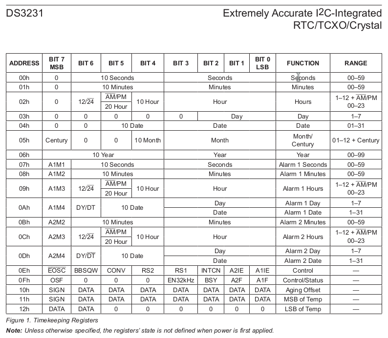
We will set up the timer in the user_init() function, further down the page. When that timer fires, it calls this function. First, we create a variable to hold the result of our i2cread call later. Because we want to cause a temperature measurement, we need to send a command to the control register. Refer to the DS3231 register map:
![]()
The control register is located at 0x0E. The bit we are interested in is CONV, which will force a conversion. Just to be on the safe side, we also set the other bits, which should already be set correctly, but better safe than sorry. This includes making sure the oscillator is enabled (/EOSC set to 0) as well as disabling the square wave output, and setting the remainder of the bits to the power-on defaults. This will start a temperature conversion and the temperature registers will be updated.
After this, we then start a new read cycle, starting at register 0x11, which is the most significant byte of the temperature. We read this, and the following register, and then we display the result to the user. Unfortunately, the os_printf() function does not seem to support displaying floating-point numbers. Therefore, I had to create an ugly work-around which displays the most significant byte (which, thankfully, is the whole part of the temperature) followed by the value of the least significant byte, with instructions to multiply that by 0.25 to get the real value. In a project which matter more than a simple example, we would likely create our own formatting function to output a floating-point number.
We then start another read cycle for the time registers, which start at 0x0. We read the first three registers, which are the seconds, minutes and hours of the current time. This is then displayed to the user. Thankfully, os_printf() does follow the printf() conversion specifiers in the C standard, so we are able to pad the output with 0s and always display 2 digits, which results in the time looking like 18:04:06 instead of 18:4:6.
Finally, we move on to the very simple user_init() function:
void ICACHE_FLASH_ATTR user_init() {
  // init I2C
  gpio_init();
  i2c_master_gpio_init();
  // set UART to 115200
  uart_div_modify(0, UART_CLK_FREQ / 115200);

  os_timer_setfn(&sampleTimer, (os_timer_func_t *)sampleTimer_f, NULL);
  os_timer_arm(&sampleTimer, 1000, 1);
}
This calls the gpio_init() function in the SDK to enable the GPIO, which is required before initialising the i2c library. The next line does just that, setting the GPIO up as required by the i2c library. The next line is a gem I recently discovered, which sets the debug output to 115200. Prior to this, I had simply been using my Bus Pirate to read the 57600 baud data, which is a rarely used speed not supported by most serial terminal software. Now we can just use the onboard serial to USB chip and any serial terminal software we like!
Finally, we set up the timers, similarly to how we did it in the first tutorial. We set it for 1000ms, which in theory should print the time every second. However, because there is some drift between the internal timer and the real-time clock, you might occasionally see a second skipped, or the same second printed twice.
And that's it! If you had trouble understanding anything, spotted any errors, or just want advice or help with any step, make sure to read the Getting Help section in the details section of this project.
 Alexander


Discussions
Become a Hackaday.io Member
Create an account to leave a comment. Already have an account? Log In.